Table of Contents
Advertisement
Quick Links
Advertisement
Table of Contents

Subscribe to Our Youtube Channel
Related Manuals for EUROCOM Notebook V09.2.00


Summary of Contents for EUROCOM Notebook V09.2.00
- Page 1 V09.2.00...
- Page 3 Preface Notice The company reserves the right to revise this publication or to change its contents without notice. Information contained herein is for reference only and does not constitute a commitment on the part of the manufacturer or any subsequent vendor. They assume no responsibility or liability for any errors or inaccuracies that may appear in this publication nor are they in anyway responsible for any loss or damage resulting from the use (or misuse) of this publication.
-
Page 4: Fcc Statement
Preface FCC Statement (Federal Communications Commission) You are cautioned that changes or modifications not expressly approved by the party responsible for compliance could void the user's authority to operate the equipment. This equipment has been tested and found to comply with the limits for a Class B digital device, pursuant to Part 15 of the FCC Rules. -
Page 5: Fcc Rf Radiation Exposure Statement
Preface FCC RF Radiation Exposure Statement: This Transmitter must not be co-located or operating in conjunction with any other antenna or transmitter. This equipment complies with FCC RF radiation exposure limits set forth for an uncontrolled environment. This equipment should be installed and operated with a minimum distance of 20 centimeters between the radiator and your body. -
Page 6: Important Safety Instructions
Preface IMPORTANT SAFETY INSTRUCTIONS Follow basic safety precautions, including those listed below, to reduce the risk of fire, electric shock, and injury to persons when using any electrical equipment: Do not use this product near water, for example near a bath tub, wash bowl, kitchen sink or laundry tub, in a wet basement or near a swimming pool. -
Page 7: Instructions For Care And Operation
Preface Instructions for Care and Operation The notebook computer is quite rugged, but it can be damaged. To prevent this, follow these suggestions: Don’t drop it, or expose it to shock. If the computer falls, the case and the components could be damaged. Do not expose the computer Do not place it on an unstable Do not place anything heavy... - Page 8 Preface Avoid interference. Keep the computer away from high capacity transformers, electric motors, and other strong magnetic fields. These can hinder proper performance and damage your data. Follow the proper working procedures for the computer. Shut the computer down properly and don’t forget to save your work.
-
Page 9: Power Safety
Preface Power Safety The computer has specific power requirements: • Only use a power adapter approved for use with this computer. • Your AC/DC adapter may be designed for international travel but it still requires a steady, uninterrupted power supply. If you are unsure of your local power specifications, Power Safety Warning consult your service representative or local power company. -
Page 10: Battery Precautions
Preface Battery Precautions • Only use batteries designed for this computer. The wrong battery type may explode, leak or damage the computer. • Do not remove any batteries from the computer while it is powered on. • Do not continue to use a battery that has been dropped, or that appears damaged (e.g. bent or twisted) in any way. Even if the computer continues to work with a damaged battery in place, it may cause circuit damage, which may possibly result in fire. -
Page 11: Cleaning
Preface Cleaning Do not apply cleaner directly to the computer; use a soft clean cloth. Do not use volatile (petroleum distillates) or abrasive cleaners on any part of the computer. Servicing Do not attempt to service the computer yourself. Doing so may violate your warranty and expose you and the computer to electric shock. -
Page 12: Travel Considerations
Preface Travel Considerations Packing As you get ready for your trip, run through this list to make sure the system is ready to go: Check that the battery pack and any spares are fully charged. Power off the computer and peripherals. Close the display panel and make sure it’s latched. - Page 13 Preface On the Road In addition to the general safety and maintenance suggestions in this preface, and Chapter 8: Troubleshooting, keep these points in mind: Hand-carry the notebook - For security, don’t let it out of your sight. In some areas, computer theft is very common.
- Page 14 Preface Developing Good Work Habits Developing good work habits is important if you need to work in front of the computer for long periods of time. Improper work habits can result in discomfort or serious injury from repetitive strain to your hands, wrists or other joints.
-
Page 15: Lcd Screen Care
Preface Lighting Proper lighting and comfortable display viewing angle can reduce eye strain and muscle fatigue in your neck and shoulders. • Position the display to avoid glare or reflections from overhead lighting or outside sources of light. • Keep the display screen clean and set the brightness and contrast to levels that allow you to see the screen clearly. •... - Page 16 Preface...
-
Page 17: Table Of Contents
Preface Contents Notice .................I Keyboard - Model A ............1-11 FCC Statement .............II Keyboard - Model B ............1-12 FCC RF Radiation Exposure Statement: ....III Function/Hot Key Indicators ........1-13 Instructions for Care and Operation ......V System Map: Front & Left Views ........1-14 Power Safety .............VII System Map: Right &... - Page 18 Preface Gestures and Device Settings ........2-9 Recharging the Battery with the AC/DC Adapter ..3-13 Audio Features .............2-11 Proper handling of the Battery Pack ......3-14 Adding a Printer ............2-12 Battery FAQ ..............3-15 USB Printer ..............2-12 Drivers & Utilities Parallel Printer ............2-12 What to Install ..............4-1 Power Management Module Driver Installation ..........4-1...
- Page 19 Preface Fingerprint Reader Module ........4-8 Set Supervisor Password (Security Menu) ....5-10 Set User Password (Security Menu) ......5-11 BIOS Utilities Fixed disk boot sector: (Security Menu) ......5-11 Password on boot: (Security Menu) ......5-11 Overview ................5-1 Boot Menu ..............5-12 The Power-On Self Test (POST) ........5-2 Exit Menu ..............5-13 Failing the POST ............5-3 Fatal Errors ..............5-3...
- Page 20 Preface Intel® Wi-Fi Link Series My WiFi Backup and General Maintenance .........8-3 Driver Installation .............7-13 Viruses ................8-4 Windows Mobility Center .........7-24 Upgrading and Adding New Hardware/Software ..8-5 PC Camera Module ............7-25 Problems and Possible Solutions ........8-7 PC Camera Driver Installation .........7-26 Screen Resolution Error ..........8-12 3.75G/HSPA Module ...........7-33 Interface (Ports &...
- Page 21 Preface Video Adapter ............... C-2 Attaching Other Displays ..........B-9 BIOS ................C-2 ATI Catalyst® Control Center ........B-11 Storage ................C-2 Display Modes ............D-15 Audio ................C-2 The Power Sources ............. D-18 Keyboard & Pointing Device ........C-2 AC/DC Adapter ............D-18 Card Reader ..............
- Page 22 Preface Driver Installation Procedure........D-35 Optional Drivers ............D-37 Bluetooth Module (Win 7) .......... D-38 Bluetooth Configuration in Windows 7 ....D-39 Wireless LAN Module (Win 7) ........D-43 Connecting to a Wireless Network ......D-45 Intel® My WiFi Installation & Configuration ..D-48 Windows Mobility Center ........
-
Page 23: Quick Start Guide
Quick Start Guide Chapter 1: Quick Start Guide Overview This Quick Start Guide is a brief introduction to the basic features of your computer, to navigating around the computer and to getting your system started. The remainder of the manual covers the following: •... -
Page 24: Advanced Users
Quick Start Guide Advanced Users If you are an advanced user you may skip over most of this Quick Start Guide. However you may find it useful to refer to “What to Install” on page 4 - “BIOS Utilities” on page 5 - 1 “Upgrading The Computer”... -
Page 25: Not Included
Quick Start Guide Not Included Operating Systems (e.g. Windows Vista/Windows 7) and applications (e.g. word processing, spreadsheet and da- tabase programs) have their own manuals, so please consult the appropriate manuals. Drivers If you are installing new system software, or are re-configuring your computer for a different system, you will need to install the drivers listed in “Drivers &... -
Page 26: System Startup
Quick Start Guide System Startup Remove all packing materials. Place the computer on a stable surface. Securely attach any peripherals you want to use with the notebook (e.g. keyboard and mouse) to their ports. Attach the AC/DC adapter to the DC-In jack on the left of the computer, then plug the AC power cord into an outlet, and connect the AC power cord to the AC/DC adapter. -
Page 27: System Software
Quick Start Guide System Software Your computer may already come with system software pre-installed. Where this is not the case, or where you are re-configuring your computer for a different system, you will find the following operating systems are sup- ported (see Appendix D for Windows 7 specific information). -
Page 28: Model Differences
Quick Start Guide Model Differences This notebook series includes two different model types. The models differ as indicated in the table below however all other features, modules and specifications are identical (see Appendix Feature Model A Model B 15.6" HD 16:9 Wide Screen (1366 * 768) / WXGA(1440 * 900) / "... -
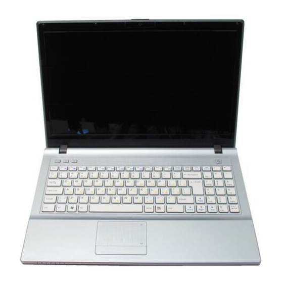
Page 29: System Map: Lcd Panel Open - Model A
Quick Start Guide System Map: LCD Panel Open - Model A Figure 1 - 2 LCD Panel Open (Model A Computers) Wireless Device Built-In PC Camera Operation Aboard Aircraft The use of any portable electronic trans- Power Button mission devices aboard aircraft is usually Hot Key Buttons prohibited. -
Page 30: System Map: Lcd Panel Open - Model B
Quick Start Guide System Map: LCD Panel Open - Model B Figure 1 - 3 LCD Panel Open (Model B Computers) Wireless Device Built-In PC Camera Operation Aboard Aircraft The use of any portable electronic Power Button transmission devices aboard air- Hot Key Buttons craft is usually prohibited. -
Page 31: Led Indicators
Quick Start Guide LED Indicators Icon Color Description The LED indicators on the computer display helpful Orange DC Power is Plugged In information about the current status of the computer. Green The Computer is On The Computer is in Sleep Icon Color Description... -
Page 32: Hot Key Buttons & Keyboard
Quick Start Guide Hot Key Buttons & Keyboard These buttons give instant access to the default Internet browser and e-mail program, Other Keyboards and allow you to toggle the Silent Mode on/off with one quick button press. If your keyboard is damaged or you just Hot Key Function... -
Page 33: Keyboard - Model A
Quick Start Guide Keyboard - Model A The keyboard has a numerical keypad on the right for easy numeric data input, and features function keys to allow you to change operational features instantly. See Table 1 - 6, on page 1 - 13 for full function key combi- nation details. -
Page 34: Keyboard - Model B
Quick Start Guide Keyboard - Model B The keyboard has a numerical keypad on the right for easy numeric data input, and features function keys to allow you to change operational features instantly. See Table 1 - 6, on page 1 - 13 for full function key combi- nation details. -
Page 35: Function/Hot Key Indicators
Quick Start Guide Function/Hot Key Indicators The function keys (F1 - F12 etc.) will act as hot keys when pressed while the Fn key is held down. In addition to the basic function key combinations; visual indicators are available when the hot key utility is installed. Fn Keys Function Fn Keys... -
Page 36: System Map: Front & Left Views
Quick Start Guide System Map: Front & Left Views Figure 1 - 6 Front & Left Views LED Power & Com- munication Indica- tors DC-In Jack External Monitor Port RJ-45 LAN Jack e-SATA Port HDMI-Out Port Vent/Fan Intake/ Outlet 7-in-1 Card Reader 2 * USB 2.0 Ports The card reader allows you to use the most popular digital storage card formats: ExpressCard Slot... -
Page 37: System Map: Right & Rear Views
Quick Start Guide System Map: Right & Rear Views Figure 1 - 7 Right & Rear Views S/PDIF-Out Jack Microphone-In Jack Headphone-Out Jack USB 2.0 Port Optical Device Drive Bay (for CD/ DVD Device - see page CD/DVD Emergency Eject Changing DVD Regional Codes RJ-11 Phone Jack Security Lock Slot... -
Page 38: System Map: Bottom View - Model A
Quick Start Guide System Map: Bottom View - Model A Figure 1 - 8 Bottom View (Model A Computers) Battery Information Battery Always completely dis- RAM & CPU Bay charge, then fully charge, a new battery before using it. Cover Completely discharge and Vent/Fan Intake/ charge the battery at least... -
Page 39: System Map: Bottom View - Model B
Quick Start Guide System Map: Bottom View - Model B Figure 1 - 9 Bottom View (Model B Computers) Battery Information Battery Always completely dis- charge, then fully charge, a RAM & CPU Bay new battery before using it. Cover Completely discharge and Vent/Fan Intake/ charge the battery at least... -
Page 40: Windows Vista Start Menu & Control Panel
Quick Start Guide Windows Vista Start Menu & Control Panel Most of the control panels, utilities and programs within Windows Vista (and most other Windows versions) are accessed from the Start menu. When you install programs and utilities they will be installed on your hard disk drive, and a shortcut will usually be placed in the Start menu and/or the desktop. -
Page 41: Video Features
Quick Start Guide Video Features You can configure display options, from the Display Settings control panel in Windows as long as the appro- priate video driver is installed. For more detailed video information see “ATI Video Driver Controls” on page B - To access Display Settings in Windows: 1. -
Page 42: Display Devices & Options
Quick Start Guide Display Devices & Options Besides the built-in LCD, you can also use an external VGA monitor (CRT)/external Flat Panel Display as your display device. Video Card Options Note that card types, specifications and drivers are subject to continual updates and changes. Check with your service center for the latest details on video cards supported. -
Page 43: Power Options
Quick Start Guide Power Options The Power Options (Hardware and Sound menu) control panel icon in Windows (see page 17) allows you to configure power management features for your computer. You can conserve power by means of power plans and configure the options for the power button, sleep button, computer lid (when closed), display and sleep mode from the left menu. - Page 44 Quick Start Guide 1 - 22...
-
Page 45: Features & Components
Features & Components Chapter 2: Features & Components Overview Read this chapter to learn more about the following main features and components of the computer: • Hard Disk Drive • Optical (CD/DVD) Device • 7-in-1 Card Reader • ExpressCard Slot •... -
Page 46: Hard Disk Drive
Features & Components Hard Disk Drive The hard disk drive is used to store your data in the computer. The hard disk can be Power Safety taken out to accommodate other 2.5" serial (SATA) hard disk drives (see “Storage” on page C - 2) with a height of 9.5 mm. -
Page 47: Optical (Cd/Dvd) Device
Features & Components Optical (CD/DVD) Device There is a bay for a 5.25" optical (CD/DVD) device (12.7mm height). The actual de- Sound Volume vice will depend on the module you purchased (see “Storage” on page C - 2). The Adjustment optical device is usually labeled “Drive D:”... -
Page 48: Handling Cds Or Dvds
Features & Components Handling CDs or DVDs Proper handling of your CDs/DVDs will prevent them from being damaged. Please follow the advice below to make sure that the data stored on your CDs/DVDs can be CD Emergency Eject accessed. If you need to manually eject a CD (e.g. -
Page 49: Dvd Regional Codes
Features & Components DVD Regional Codes To change the DVD regional codes see “Changing DVD Regional Codes” on page 1 - DVD Regional Coding Table 2 - 1 Region Geographical Location DVD Regional Coding USA, Canada Western Europe, Japan, South Africa, Middle East &... -
Page 50: 7-In-1 Card Reader
Features & Components 7-in-1 Card Reader The card reader allows you to use some of the latest digital storage cards. Push the Card Reader Cover card into the slot and it will appear as a removable device, and can be accessed in the same way as your hard disk (s). -
Page 51: Expresscard Slot
Features & Components ExpressCard Slot The computer is equipped with an ExpressCard/34/54 slot that reads Express Card/ ExpressCard 34 and ExpressCard/54 formats. ExpressCards are the successors to PCMCIA (PC Slot Cover Cards). Make sure you install the Card Reader driver (see “CardReader”... -
Page 52: Touchpad And Buttons/Mouse
Features & Components TouchPad and Buttons/Mouse The TouchPad is an alternative to the mouse; however, you can also add a mouse to Mouse Driver your computer through one of the USB ports. The TouchPad buttons function in much the same way as a two-button mouse. If you are using an ex- ternal mouse your op- Once you have installed the TouchPad driver (see... -
Page 53: Gestures And Device Settings
Features & Components Gestures and Device Settings The Synaptics Gestures Suite application allows you to use a specific gesture (ac- tion) on the surface of the TouchPad to perform specific actions to manipulate doc- uments, objects and applications. You can configure the settings from the Device Settings tab in Mouse Properties: Click Start, and click Control Panel (or point to Settings and click Control Panel). - Page 54 Features & Components Scrolling The two finger scrolling feature works in most scrollable windows and allows you to scroll horizontally and vertically. Place two fingers, slightly separated, on the Show Video TouchPad surface and slide both fingers in the direction required (in a straight con- You can get a clearer tinuous motion).
-
Page 55: Audio Features
Features & Components Audio Features You can configure the audio options on your computer from the Sound control Sound Volume panel in Windows, or from the Realtek HD Audio Manager icon in the taskbar/ Adjustment control panel (right-click the taskbar icon bring up an audio menu). -
Page 56: Adding A Printer
Features & Components Adding a Printer The most commonly used peripheral is a printer. The following conventions will Parallel Printer help you to add a printer; however it is always best to refer to the printer manual for specific instructions and configuration options. After setting up the print- er attach the parallel ca- ble to the printer. -
Page 57: Power Management
Power Management Chapter 3: Power Management Overview OS Note Power management To conserve power, especially when using the battery, your computer power man- functions will vary slight- agement conserves power by controlling individual components of the computer ly depending on your (the monitor and hard disk drive) or the whole system. -
Page 58: The Power Sources
Power Management The Power Sources The computer can be powered by either an AC/DC adapter or a battery pack. Silent Mode AC/DC Adapter Use the key to tog- gle Silent Mode to re- Use only the AC/DC adapter that comes with your computer. The wrong type of AC/ duce fan noise and save DC adapter will damage the computer and its components. -
Page 59: Turning On The Computer
Power Management Turning on the Computer Now you are ready to begin using your computer. To turn it on simply press the pow- Shut Down er button on the front panel. Note that you should al- When the computer is on, you can use the power button as a Sleep/Hibernate hot- ways shut your comput- er down by choosing the key button when it is pressed for less than 4 seconds (pressing and holding the power... -
Page 60: Power Plans
Power Management Power Plans The computer can be configured to conserve power by means of power plans. You Resuming can use (or modify) an existing power plan, or create a new one. Operation The settings may be adjusted to set the display to turn off after a specified time, and Table 3 - 1, on to send the computer into Sleep after a period of inactivity. - Page 61 Power Management Each Windows power plan will also adjust the processor performance of your ma- chine in order to save power. This is worth bearing in mind if you are experiencing any reduced performance (especially under DC/battery power). ATI PowerPlay ™...
-
Page 62: Power-Saving States
Power Management Power-Saving States You can use power-saving states to stop the computer’s operation and restart where Power Button you left off. Sleep is the default power-saving state in Windows Vista. The Power Button Earlier versions of Windows used Stand By and Hibernate as system power-saving in the Start Menu (in Classic View use the states. -
Page 63: Hibernate
Power Management Hibernate Hibernate uses the least amount of power of all the power-saving states and saves all of your information on a part of the hard disk before it turns the system off. If a power failure occurs the system can restore your work from the hard disk; if a power failure occurs when work is saved only to memory, then the work will be lost. -
Page 64: Configuring The Power Buttons
Power Management Configuring the Power Buttons The power/sleep button (Fn + F4 key combo) and closed lid may be set to send the Password computer in to a power-saving state. Protection It is recommended that you enable a password on wake up in order to protect your data. -
Page 65: Resuming Operation
Power Management Resuming Operation You can resume operation from power-saving states by pressing the power button, or in some cases pressing the sleep button (Fn + F4 key combo). Closing the Lid If you have chosen to Power Status To Resume Icon Color send the computer to... -
Page 66: Energy Star Power Saving
Power Management Energy Star Power Saving This system supports Energy Star power management features that place comput- ers (CPU, hard drive, etc.) into a low-power sleep modes after a designated period of inactivity. If you want to enable Energy Star power saving then follow these in- structions: Right-click the taskbar icon Select Power Conservation Modes. -
Page 67: Battery Information
Power Management Battery Information Follow these simple guidelines to get the best use out of your battery. Low Battery Warning Battery Power Your computer’s battery power is dependent upon many factors, including the pro- When the battery is criti- cally low, immediately grams you are running, and peripheral devices attached. -
Page 68: Conserving Battery Power
Power Management Conserving Battery Power • Use a power plan that conserves power (e.g Power saver), however note that this may have an affect on computer performance. Windows Mobility Center • Lower the brightness level of the LCD display. The system will decrease LCD brightness slightly to save power when it is not powered by the AC/DC adapter. -
Page 69: Battery Life
Power Management Battery Life Battery life may be shortened through improper maintenance. To optimize the life and improve its performance, fully discharge and recharge the battery at least once every 30 days. We recommend that you do not remove the battery yourself. If you do need to re- move the battery for any reason (e.g. -
Page 70: Proper Handling Of The Battery Pack
Power Management Proper handling of the Battery Pack • DO NOT disassemble the battery pack under any circumstances • DO NOT expose the battery to fire or high temperatures, it may explode Caution • DO NOT connect the metal terminals (+, -) to each other Danger of explosion if battery is incorrectly re- placed. -
Page 71: Battery Faq
Power Management Battery FAQ How do I completely discharge the battery? Use the computer with battery power until it shuts down due to a low battery. Don’t turn off the computer even if a message indicates the battery is critically low, just let the computer use up all of the battery power and shut down on its own. - Page 72 Power Management Scroll down to Battery and click + to expand the battery options. Choose the options below (click Yes if a warning appears): Figure 3 - 9 Power Options Advanced Settings - Battery • Low battery levels = 0% •...
- Page 73 Power Management How do I fully charge the battery? When charging the battery, don’t stop until the LED charging indicator light changes from orange to green. How do I maintain the battery? Completely discharge and charge the battery at least once every 30 days or after about 20 partial discharges.
- Page 74 Power Management 3 - 18...
-
Page 75: Drivers & Utilities
Drivers & Utilities Chapter 4: Drivers & Utilities What to Install This chapter deals with installing the drivers and utili- ties essential to the operation or improvement of some The Device Drivers & Utilities + User’s Manual disc of the computer’s subsystems. The system takes ad- contains the drivers and utilities necessary for the vantage of some newer hardware components for proper operation of the computer. -
Page 76: Driver Installation
Drivers & Utilities Driver Installation Check the driver installation order from Table 4 - 1, on page 4 - 3 (the drivers must be installed in Insert the Device Drivers & Utilities + User’s Manual this order) which is the same as that listed in the Drivers Installer menu below. - Page 77 Drivers & Utilities Manual Driver Installation Click Browse CD (button) in the Drivers Installer ap- Driver - Windows Vista with Service Pack 2 Page plication and browse to the executable file in the ap- Chipset Page 4 - 5 propriate driver folder. Video Page 4 - 5 Windows Update...
-
Page 78: Updating/Reinstalling Individual Drivers
Drivers & Utilities Updating/Reinstalling Individual Drivers User Account Control (Win Vista) If you wish to update/reinstall individual drivers it If a User Account Control prompt appears as part of may be necessary to uninstall the original driver.To do the driver installation procedure, click Continue or this go to the Control Panel in the Windows OS and Allow, and follow the installation procedure as direct- double-click the Programs and Features icon (Pro-... -
Page 79: New Hardware Found
Drivers & Utilities New Hardware Found Driver Installation Procedure If you see the message “New Hardware Found” dur- Insert the Device Drivers & Utilities + User’s Manual ing the installation procedure (other than when out- disc and click Install Drivers (button). lined in the driver install procedure), click Cancel Chipset to close the window, and follow the installation proce-... -
Page 80: Audio
Drivers & Utilities Audio TouchPad 1. Click 3.Install Audio Driver > Yes. 1. Click 6.Install Touchpad Driver > Yes. 2. Click Next. 2. Click Next. 3. Click Finish to restart the computer. 3. Click the button to accept the license, and then click Next. -
Page 81: Optional Drivers
Drivers & Utilities Optional Drivers See the pages indicated for the driver installation pro- cedures for any modules included in your purchase op- Windows Update tion. After installing all the drivers make sure you enable Win- dows Update in order to get all the latest security up- dates etc. -
Page 82: Wireless Lan Module
Drivers & Utilities Bluetooth Module 3.75G/HSPA Module Note: The operating system is the default setting for See the introduction in “3.75G/HSPA Module” on Bluetooth control in Windows Vista, and does not re- page 7 - 33, and check the installation procedure. quire a driver. -
Page 83: Bios Utilities
BIOS Utilities Chapter 5: BIOS Utilities Overview BIOS Settings Warning This chapter gives a brief introduction to the computer’s built-in software: Incorrect settings can cause your system to Diagnostics: The POST (Power-On Self Test) malfunction. To correct mistakes, return to Set- up and restore the Set- Configuration: The Setup utility up Defaults with <F9>. -
Page 84: The Power-On Self Test (Post)
BIOS Utilities The Power-On Self Test (POST) Each time you turn on the computer, the system takes a few seconds to conduct a POST Screen POST, including a quick test of the on-board RAM (memory). 1.BIOS information As the POST proceeds, the computer will tell you if there is anything wrong. If there 2.CPU type is a problem that prevents the system from booting, it will display a system summary 3.Memory status... -
Page 85: Failing The Post
BIOS Utilities Failing the POST Errors can be detected during the POST. There are two categories, “fatal” and “non- fatal”. Fatal Errors These stop the boot process and usually indicate there is something seriously wrong with your system. Take the computer to your service representative or authorized service center as soon as possible. -
Page 86: The Setup Program
BIOS Utilities The Setup Program The Phoenix Setup program tells the system how to configure itself and manage ba- sic features and subsystems (e.g. port configuration). Entering Setup To enter Setup, turn on the computer and press F2 during the POST. The prompt (Press F2 to Enter Setup) seen on page 5 - 2 is usually present for a few seconds... -
Page 87: Setup Screens
BIOS Utilities Setup Screens The following pages contain additional advice on portions of the Setup. Setup Menus Along the top of the screen is a menu bar with menu headings. When you select a Setup menus heading, a new screen appears. Scroll through the features listed on each screen to shown in this section are make changes to Setup. -
Page 88: Main Menu
BIOS Utilities Main Menu Figure 5 - 2 Main Menu System Time & Date (Main Menu) The hour setting uses the 24-hour system (i.e., ØØ = midnight; 13 = 1 pm). If you can change the date and time settings in your operating system, you will also change these settings. -
Page 89: Sata Port 1/2/5 (Main Menu)
BIOS Utilities SATA Port 1/2/5 (Main Menu) Pressing Enter opens the sub-menu to show the configuration of an HDD/optical de- vice on the computer’s SATA Port 1/2/5. Use the Auto (Type:) setting to have the items configured automatically for you. System Memory (Main Menu) This item contains information on the system memory, and is not user configurable. -
Page 90: Advanced Menu
BIOS Utilities Advanced Menu Figure 5 - 3 Advanced Menu Legacy USB Support (Advanced Menu) Use this menu item to enable/disable the support for Legacy Universal Serial Bus in non-USB aware operating systems. 5 - 8 Advanced Menu... -
Page 91: Boot-Time Diagnostic Screen (Advanced Menu)
BIOS Utilities Boot-time Diagnostic Screen (Advanced Menu) Use this menu item to enable/disable the Boot-time Diagnostic Screen or Power-On Self Test (see “The Power-On Self Test (POST)” on page 5 - Legacy OS Boot: (Advanced Menu) Enable this item to support only system boot from the Legacy OS (e.g Windows Vis- ta). -
Page 92: Security Menu
BIOS Utilities Security Menu Security Menu changes make here affect the access to the Setup utility itself, and also access to your ma- chine as it boots up af- ter you turn it on. These settings do not affect your machine or network passwords which will be set in... -
Page 93: Set User Password (Security Menu)
BIOS Utilities Set User Password (Security Menu) You can set a password for user mode access to the PhoenixBIOS Setup Utility. This will not affect access to the computer OS, (only the Setup utility) unless you Password Warning choose to set a Password on Boot (see below). Many menu items in the Phoenix- BIOS Setup Utility cannot be modified in user mode. -
Page 94: Boot Menu
BIOS Utilities Boot Menu Figure 5 - 5 Boot Menu When you turn the computer on it will look for an operating system (e.g. Windows Vista) from the devices listed in this menu, and in this priority order. If it cannot find the operating system on that device, it will try to load it from the next device in the order specified in the Boot priority order. -
Page 95: Exit Menu
BIOS Utilities Exit Menu Figure 5 - 6 Exit Menu Choosing to Discard Changes, or Exit Discarding Changes, will wipe out any changes you have made to the Setup. You can also choose to restore the original Set- up defaults that will return the Setup to its original state, and erase any previous changes you have made in a previous session. - Page 96 BIOS Utilities 5 - 14...
-
Page 97: Upgrading The Computer
Upgrading The Computer Chapter 6: Upgrading The Computer Overview This chapter contains information on upgrading the computer. Follow the steps out- lined to make the desired upgrades. If you have any trouble or problems you can con- Warranty Warning tact your service representative for further help. Before you begin you will need: Please check with your service representative... -
Page 98: When Not To Upgrade
Upgrading The Computer When Not to Upgrade These procedures involve opening the system’s case, adding and sometimes replac- ing parts. Power Safety Warning You should not perform any of these upgrades if: Before you undertake • Your system is still under warranty or a service contract upgrade proce- •... -
Page 99: Removing The Battery
Upgrading The Computer Removing the Battery If you are confident in undertaking upgrade procedures yourself, for safety reasons Warranty Warning it is best to remove the battery. Turn the computer off, and turn it over. Please check with your Slide the latch in the direction of the arrow. -
Page 100: Upgrading The Hard Disk Drive
Upgrading The Computer Upgrading the Hard Disk Drive The hard disk drive can be taken out to accommodate other 2.5" serial (SATA) hard HDD System disk drives with a height of 9.5mm (h) (see “Storage” on page C - 2). Follow your Warning operating system’s installation instructions, and install all necessary drivers and util- ities (see... - Page 101 Upgrading The Computer Grip the tab and slide the hard disk in the direction of arrow Lift the hard disk out of the bay Model A Figure 6 - 3 HDD Assembly Removal Model B Upgrading the Hard Disk Drive 6 - 5...
- Page 102 Upgrading The Computer Remove the screw(s) (for Model B only) and the adhesive cover Reverse the process to install a new hard disk drive (do not forget to replace all the screws and covers). Hard Disk Screws & Model B Cover The hard disks and cov- Figure 6 - 4...
-
Page 103: Upgrading The Optical (Cd/Dvd) Device
Upgrading The Computer Upgrading the Optical (CD/DVD) Device Turn off the computer, and turn it over and remove the battery. Locate the hard disk bay cover and loosen screws & Remove the hard disk bay cover Model A Model B Figure 6 - 5 Removing the HDD Cover... - Page 104 Upgrading The Computer Remove the screw at point , and use a screwdriver to carefully push out the optical device at point Reverse the process to install the new device. Figure 6 - 6 Removing the Optical Device 6 - 8 Upgrading the Optical (CD/DVD) Device...
-
Page 105: Upgrading The System Memory (Ram)
Upgrading The Computer Upgrading the System Memory (RAM) The computer has two memory sockets for 204 pin Small Outline Dual In-line (SO- DIMM) DDRIII (DDR3) type memory modules (see “Memory” on page C - 2 details of supported module types). Turn off the computer, and turn it over and remove the battery. - Page 106 Upgrading The Computer Carefully (a fan and cable are attached to the under side of the cover) lift up the bay cover. Carefully disconnect the fan cable , and remove the cover Fan Cable & Cover Make sure you recon- Model A nect the fan cable before screwing down...
- Page 107 Upgrading The Computer Gently pull the two release latches on the sides of the memory socket in the direction indicated by the arrows ( & Figure 6 - The RAM module will pop-up, and you can remove it. Pull the latches to release the second module if necessary. Insert a new module holding it at about a 30°...
- Page 108 Upgrading The Computer 10. Press the module in and down towards the mainboard until the slot levers click into place to secure the module. 11. Replace the bay cover (see sidebar and below for Model A Computers) and Cover Pins screws (make sure you reconnect the fan cable before screwing down the bay cover).
-
Page 109: Modules & Options
Modules & Options Chapter 7: Modules & Options Overview Wireless Device Operation Aboard This chapter contains information on the following modules, which may come with Aircraft your computer, depending on the configuration purchased. If you are unsure please The use of any portable contact your service representative. -
Page 110: Bluetooth Module
Modules & Options Bluetooth Module The operating system’s Bluetooth Devices control panel is used to configure the Wireless Device Bluetooth settings in Windows Vista, and therefore does not require a driver. Use Operation Aboard the Fn + F12 key combination (see “Function/Hot Key Indicators”... -
Page 111: Bluetooth Configuration In Windows Vista
Modules & Options Bluetooth Configuration in Windows Vista Setup your Bluetooth Device so the Computer Can Find it Turn your Bluetooth device (e.g. PDA, mobile phone etc.) on. Bluetooth Taskbar Make the device discoverable (to do this check your device documentation). Icon To Turn the Bluetooth Module On If you cannot see the... - Page 112 Modules & Options To Add a Bluetooth Device Access the Bluetooth Devices control panel and click Bluetooth Settings. Click Options (tab), and make sure that Allow Bluetooth devices to connect to Pairing Options this computer check box (Connections) has a tick inside it, and click OK. Click Add Wireless Device in the Bluetooth Devices control panel.
- Page 113 Modules & Options Enter the code into your Bluetooth enabled device and follow any on-screen instructions to complete the pairing. Figure 7 - 3 Pairing Codes Pairing Code Example The example outlined here shows a connection to a mobile device. Other devices e.g. computers, may have a slightly different connection proce- dure, and may require you to confirm a pairing code is correct on both devices.
- Page 114 Modules & Options To Change Settings for the Bluetooth Device Access the Bluetooth Devices control panel. Click on the device you want to change and click Properties to: Bluetooth Help • Change the name of the device (click General, type a new name and click OK). •...
-
Page 115: Wireless Lan Module
Modules & Options Wireless LAN Module If you have included an Intel® Wi-Fi Link 5300 Series, Intel® Advanced N Wi-Fi Wireless Device Link 6200, Intel® Ultimate N Wi-Fi Link 6300, 3rd Party 802.11b/g or 3rd Party Operation Aboard 802.11b/g/n WLAN module in your purchase option, make sure that the Wireless Aircraft LAN module is on before installing the driver. -
Page 116: Intel® Wi-Fi Link Series Driver Installation
Modules & Options Intel® Wi-Fi Link Series Driver Installation If you see the message “Found New Hardware” click Cancel to close the window. 1. Make sure the module is powered on, then insert the Device Drivers & Util- Intel(R) PROSet/ ities + User’s Manual disc into the CD/DVD drive. -
Page 117: Connecting To A Wireless Network
Modules & Options Connecting to a Wireless Network Make sure the Wireless LAN module is turned on. Click the taskbar wireless icon , and then click Connect to a network (or right- click the icon , and then click Connect to a network). Figure 7 - 6 Taskbar Menus Click icon... - Page 118 Modules & Options Click a network, and then click Connect. If you do not see a network you want to connect to, click Set up a connection or network (a list of options will appear allowing manual searching, and creating a new network).
- Page 119 Modules & Options To disconnect from the wireless network you can click the taskbar wireless icon and then select Connect or disconnect to access the network menu, and click Disconnect (or right-click the icon , and then click Disconnect from). Security Enabled Networks You should try to make...
-
Page 120: Intel® My Wifi Installation & Configuration
Modules & Options Intel My WiFi Installation & Configuration ® Intel® My WiFi Technology uses your WLAN module to allow you to connect up to eight other WiFi enabled devices (e.g. digital cameras, other computers, cell Intel® My WiFi Help phones, handheld devices etc.) to your computer (similar to Bluetooth), while still To get help on Intel®... -
Page 121: Intel® Wi-Fi Link Series My Wifi Driver Installation
Modules & Options Intel® Wi-Fi Link Series My WiFi Driver Installation If you see the message “Found New Hardware” click Cancel to close the window. 1. Make sure the module is powered on, then insert the Device Drivers & Util- Intel(R) PROSet/ ities + User’s Manual disc into the CD/DVD drive. - Page 122 Modules & Options Intel® My WiFi Configuration You can configure the My WiFi settings as follows. Access the Intel® My WiFi Utility from the Start menu (Start > Programs/All Programs > Intel PROSet Wireless > Intel My WiFi Technology), or by clicking the taskbar icon Click Enable (on the first run of the program there will be no connected...
- Page 123 Modules & Options Click Start, and click Control Panel (or point to Settings and click Control Panel). Click Network and Sharing Center (Network and Internet). Click Manage Network Connections. Click Manage Network Connections Figure 7 - 13 Network and Sharing Center Right-click Intel WiFi STA (Station) in Network Connections and select Properties.
- Page 124 Modules & Options Click Sharing (tab) and select “Allow other network users to connect through this computer’s Internet connection”. Select Intel My WiFi PAN under Home Networking Connection. Click OK. Click “Allow other network users to connect through this computer’s Internet connection”.
- Page 125 Modules & Options 10. A message will appear to inform you that the LAN adapter will be set to use the IP address 192.168.0.1. Figure 7 - 16 11. Click Yes to enable Internet Connection Sharing. IP Address Warning IP Addresses The Intel®...
- Page 126 Modules & Options 14. Click Profiles, click Intel Wireless PAN and click Edit. Figure 7 - 18 Profiles 15. You can change the Profile Name and Network Name to your personal preferences in General (tab). Profile and Network Names Figure 7 - 19 The Profile Name is the name as Intel®...
- Page 127 Modules & Options 16. Click Security (tab). 17. Change the Security Type to WEP and the Encryption Type to 64bit. 18. Enter a password (5 characters long) in the Passphrase box. Figure 7 - 20 Intel® My WiFi Profile Settings - Security Wireless LAN Module 7 - 19...
- Page 128 Modules & Options 19. Click Sharing (tab). 20. Make sure Filter Network Traffic and DHCP and DNS Server are Disabled. Set Filter Network Traffic & DHCP and DNS Servers to Disabled. Figure 7 - 21 Intel® My WiFi Profile Settings - Sharing 7 - 20 Wireless LAN Module...
- Page 129 Modules & Options 21. Click Advanced (tab). 22. Make sure the Default Channel is set to Channel 1, 6 or 11. 23. Click OK to save all the settings and click Close to exit Profiles. Figure 7 - 22 Intel® My WiFi Profile Settings - Advanced Wireless LAN Module 7 - 21...
- Page 130 Modules & Options 24. Double-click Intel My WiFi PAN (Personal Area Network) in Network Connections. 25. Click Details to display the Network Connection Details. Figure 7 - 23 Intel My WiFi PAN Network Connection Details (Network Connections) 7 - 22 Wireless LAN Module...
- Page 131 Modules & Options 26. Access the Intel® My WiFi Utility from the Start menu (Start > Programs/All Programs > Intel PROSet Wireless > Intel My WiFi Technology), or by clicking the taskbar icon 27. To add a new device follow the instructions in the devices’ user guide for connecting to a WiFi network.
-
Page 132: Windows Mobility Center
Modules & Options Windows Mobility Center The Windows Mobility Center control panel provides an easy point of access for information on battery status, power plans used and wireless device status etc. To access the Windows Mobility Center: Click Start, and click Control Panel (or point to Settings and click Control Panel). -
Page 133: Pc Camera Module
Modules & Options PC Camera Module Make sure that the PC Camera module is on before installing the driver and use the Latest PC Camera Fn + F10 key combination (see “Function/Hot Key Indicators” on page 1 - 13) to Driver Information toggle power to the PC Camera module. -
Page 134: Pc Camera Driver Installation
Modules & Options PC Camera Driver Installation 1. Make sure the module is powered on, then insert the Device Drivers & Util- ities + User’s Manual disc into the CD/DVD drive. PC Camera Screen 2. Click Option Drivers (button). Refresh 3. - Page 135 Modules & Options PC Camera Audio Setup If you wish to capture video & audio with your camera, it is necessary to setup the audio recording options in Windows. Click Start, and click Control Panel (or point to Settings and click Control Panel). Double-click Sound (Hardware and Sound).
- Page 136 Modules & Options Figure 7 - 26 Audio Setup for PC Camera Right-click 7 - 28 PC Camera Module...
- Page 137 Modules & Options BisonCap BisonCap is a video viewer for general purpose video viewing and testing, and for capturing video files to .avi format. Pre-Allocating File Space Run the BisonCap program from the Start > Programs/All Programs > Bison- Cam menu (it is recommended that you set the capture file before the capture You may pre-allocate the process - see Set Capture File below).
- Page 138 Modules & Options Reducing Video File Size Note that capturing high resolution video files requires a substantial amount of disk space for each file. After recording video, check the video file size (right-click the file and select Properties) and the remaining free space on your hard disk (go to My Computer, right-click the hard disk, and select Properties).
- Page 139 Modules & Options Eliminating Screen Flicker If you find that the video screen in the BisonCap program is flickering, you can try to adjust the setting in the Video Capture Filter options. Run the BisonCap program. Go to Options and scroll down to select Video Capture Filter..Click either 50Hz or 60Hz under Frequency in Property Page (tab).
- Page 140 Modules & Options Zoom The BisonCap program allows you to zoom the camera in and out. Run the BisonCap program. Go to Zoom and select Zoom Out/Zoom In. Figure 7 - 28 Zoom/Setting Taking Still Pictures Snapshot Folder The BisonCap program allows you to take still pictures. The Snapshot folder’s Run the BisonCap program.
-
Page 141: 3.75G/Hspa Module
Modules & Options 3.75G/HSPA Module If you have included an optional 3.75G/HSPA (High Speed Packet Access) module 3.75G/HSPA Module (see “Communication” on page C - 3 for specification details) in your purchase op- Options tion, you will have the appropriate application (HSPA Modem Interface or Mobile Partner) provided for your particular module. - Page 142 Modules & Options Before installing the application, make sure that the 3.75G/HSPA module is ON (installing the driver with the module off will not allow the software to detect the module hardware correctly). Use the Fn + key combination (see “Function/Hot 3.75G/HSPA Key Indicators”...
- Page 143 Modules & Options For Model A Turn off the computer, and turn it over and remove the battery. Locate the SIM card cover and loosen screw Power Safety Remove the SIM card cover Warning For Model B Before you undertake Turn off the computer, and turn it over and remove the battery.
- Page 144 Modules & Options Insert the USIM card as you would into your mobile phone. Slide the SIMLOCK towards the hinge (in the opposite direction to the arrow illustrated in Figure 7 - 31) in order to release the lock and lift it up. Insert the USIM card as illustrated in (Figure 7 - 30) and close the SIMLOCK.
-
Page 145: Hspa Modem Interface
Modules & Options HSPA Modem Interface With the 3.75G/HSPA module and USIM card (supplied by your service provider) installed you may then install the HSPA Modem Interface. The HSPA Modem In- Wireless Device terface allows you to directly access your HSPA internet service from the computer. Operation Aboard Aircraft HSPA Modem Interface Installation... -
Page 146: Hspa Modem Interface
Modules & Options HSPA Modem Interface The connection information is stored on the USIM card supplied by the service pro- vider. HSPA Modem Help Power on the 3.75G/HSPA module using the Fn + key combination. To get help on 3.75G/ Access the HSPA Modem Interface from the Start menu (Start >... - Page 147 Modules & Options Click Connect to connect to your service provider. Figure 7 - 33 Connecting to Network The message “Network is connected” will be displayed when the network connection is successful. Figure 7 - 34 Network is Connected You can then access the internet, download e-mail etc. as per any internet connection.
-
Page 148: Adding A Profile
Modules & Options While you are connected the upper right corner of the HSPA Modem interface will display the upload and download rates, and the taskbar icon will display the Figure 7 - 35 connection speed. Uploading/ Downloading Rates and Speed 10. - Page 149 Modules & Options Click Add (button) and input any Network Settings required by your service provider. Click OK to save the profile. Figure 7 - 37 Network Settings & Profiles You can Edit or Delete profiles from the Profiles tab. To use a profile click to select it, and then click Apply (button) and the settings will be transferred to Connection Manager.
-
Page 150: Contacts
Modules & Options Contacts Access the HSPA Modem Interface from the Start menu (Start > Programs/All Programs > HSPA Modem > HSPA Modem), or by clicking the desktop icon. Click Contacts (button). Figure 7 - 38 Network Settings & Profiles Click Refresh (button) to download the contacts from the USIM card to the computer. -
Page 151: Messages
Modules & Options Messages Access the HSPA Modem Interface from the Start menu (Start > Programs/All Programs > HSPA Modem > HSPA Modem), or by clicking the desktop icon. SMS Service Click Messages (button). In addition to standard in- ternet services you may also send and receive SMS text messages us- ing the HSPA Modem In-... -
Page 152: Settings
Modules & Options Click to select a contact from the list and then click Add (button) and the phone number will automatically be added to the recipient field. Type the message information into the message body and click Send (button) to send it, or Save to draft (button) to save the message. - Page 153 Modules & Options Click OK alongside any of the options to configure the settings. The Network can be configured for an Automatic (usually from the USIM card) or Manual connection. The Network Mode can be configured for any appropriate mode required. Figure 7 - 41 Settings - Network/ Network Mode...
-
Page 154: Mobile Partner
Modules & Options Mobile Partner With the 3.75G/HSPA module and USIM card (supplied by your service provider) installed you may then install the Mobile Partner application. The Mobile Partner Wireless Device application allows you to directly access your HSPA internet service from the com- Operation Aboard Aircraft puter. -
Page 155: Mobile Partner Application
Modules & Options Mobile Partner Application You will need to contact your service provider to obtain the exact details of how ex- actly to configure the settings on this page. Mobile Partner Help Profile Management To get help on Mobile Partner configuration Power on the 3.75G/HSPA module using the Fn +... - Page 156 Modules & Options Connecting to the Service Provider Power on the 3.75G/HSPA module using the Fn + key combination. Access the Mobile Partner application from the Start menu (Start > Programs/ All Programs > Mobile Partner), or by double-clicking the Mobile Partner icon on the desktop The software will run and you can select the Profile Name from the menu.
- Page 157 Modules & Options When the connection is successful you can move the cursor over the network icon in the taskbar to display the connection information. Figure 7 - 45 Connected Taskbar Notification You can then access the internet, download e-mail etc. as per any internet connection.
- Page 158 Modules & Options 11. The module will still be on, and you will need to press the Fn + key combination to turn it off. 12. If you click the Mobile Partner close icon a message will be displayed asking you to click OK to confirm the program exit and to terminate the connection.
-
Page 159: Fingerprint Reader Module
Modules & Options Fingerprint Reader Module The fingerprint reader module provides a high level of security for your computer. Help & Manual Make sure you have administrator’s rights to your computer, and have a Windows password enabled for full security protection. Right-click the taskbar icon to bring up the menu to Before beginning the enrollment process it is recommended that you go through the... -
Page 160: User Enrollment
Modules & Options User Enrollment Click Start > Programs/All Programs > Protector Suite > Control Center, or double click the taskbar icon (click Initialize). Fingerprint On the first run of the program you will be asked to click the Accept button to Enrollment accept the license. - Page 161 Modules & Options Click the button above any of the fingers to begin the enrollment process for that finger. Swipe the finger until the progress bar reaches 100% to enroll that finger. Fingerprint Repeat the process for all the fingers you wish to enroll (see sidebar), and then Enrollment click Save and Continue.
- Page 162 Modules & Options 11. Right-click the taskbar icon and select Start Control Center (and then swipe a finger) to allow you to Edit Fingerprints, register Applications, edit Settings and access the Help menu etc. You can also run the Control Center etc. from the Protector Suite item in the Programs/All Programs menu 12.
-
Page 163: Fingerprint Control Center Features
Modules & Options Fingerprint Control Center Features Application Launcher Help The Application Launcher allows you to register applications to be launched when assigned to a particular finger. Simply copy the application icon on to one of the reg- For more information on istered fingers and ten click OK to close the application window. - Page 164 Modules & Options 7 - 56...
-
Page 165: Troubleshooting
Troubleshooting Chapter 8: Troubleshooting Overview Should you have any problems with your computer, before consulting your service representative, you may want to try to solve the problem yourself. This chapter lists some common problems and their possible solutions. This can’t anticipate every problem, but you should check here before you panic. If you don’t find the answer in these pages, make sure you have followed the instructions carefully and observed the safety precautions in the preface. -
Page 166: Basic Hints And Tips
Troubleshooting Basic Hints and Tips Many of the following may seem obvious but they are often the solution to a problem when your computer ap- pears not to be working. • Power - Is the computer actually plugged into a working electrical outlet? If plugged into a power strip, make sure it is actually working. -
Page 167: Backup And General Maintenance
Troubleshooting Backup and General Maintenance • Always backup your important data, and keep copies of your OS and programs safe, but close to hand. Don’t forget to note the serial numbers if you are storing them out of their original cases, e.g. in a CD wal- let. -
Page 168: Viruses
Troubleshooting Viruses • Install an Anti-Virus program and keep the definitions file (the file which tells your program which viruses to look for) up to date. New computer viruses are discovered daily, and some of them may seriously harm your computer and cause you to lose data. Anti-Virus programs are commercially available and the defini- tions file updates are usually downloadable directly from the internet. -
Page 169: Upgrading And Adding New Hardware/Software
Troubleshooting Upgrading and Adding New Hardware/Software • Do not be tempted to make changes to your Windows Registry unless you are very sure of what you are doing, otherwise you will risk severely damaging your system. • Don’t open your computer or undertake any repair or upgrade work if you are not comfortable with what you are doing. - Page 170 Troubleshooting • Thoroughly check any recent changes you made to your system as these changes may affect one or more system components, or software programs. If possible, go back and undo the change you just made and see if the problem still occurs. •...
-
Page 171: Problems And Possible Solutions
Troubleshooting Problems and Possible Solutions Problem Possible Cause - Solution You turned on the power but it doesn’t Battery missing / incorrectly installed. Check the battery bay, make sure the work. battery is present and seated properly (the design of the battery only allows it to go in one way). - Page 172 Troubleshooting Problem Possible Cause - Solution The computer feels too hot. Make sure the computer is properly ventilated and the Vent/Fan intakes are not blocked. If this doesn’t cool it down, put the system into Hibernate mode or turn it off for an hour. Make sure the computer isn’t sitting on a thermal surface (see “Overheating”...
- Page 173 Troubleshooting Problem Possible Cause - Solution You forget the boot password. If you forget the password, you may have to discharge the battery of the CMOS. Contact your service representative for help. Password Warning If you choose to set a boot password, NEVER forget your password. The consequences of this could be serious. If you cannot remember your boot password you must contact your vendor and you may lose all of the information on your hard disk.
- Page 174 Troubleshooting Problem Possible Cause - Solution Other Keyboards If your keyboard is damaged or you just want to make a change, you can use any standard USB keyboard. The system will detect and enable it automatically. However special functions/hot keys unique to the system’s regular keyboard may not work.
- Page 175 Troubleshooting Problem Possible Cause - Solution The PC Camera module cannot be The module is off. Press the Fn + F10 key combination in order to enable the detected. module (see “Function/Hot Key Indicators” on page 1 - 13). Run the BisonCap program to view the camera picture.
-
Page 176: Screen Resolution Error
Troubleshooting Screen Resolution Error If you are experiencing either screen resolution reduction, or screen flickering after resuming from Sleep in Windows Vista only then follow the instructions below to fix this problem. This error arises in compliance with Windows Vista policy, which triggers TMM (Transient Multi-Monitor Manager) when the notebook lid (S3) is closed. - Page 177 Troubleshooting Double-click Task Scheduler Library > Microsoft > Windows. Click MobilePC to open the control panel. Right-click TMM and select Disable. Figure 8 - 2 - TMM Disable Close all the control panels. Screen Resolution Error 8 - 13...
- Page 178 Troubleshooting 8 - 14...
-
Page 179: Interface (Ports & Jacks)
Interface (Ports & Jacks) Appendix A: Interface (Ports & Jacks) Overview The following chapter will give a quick description of the interface (ports & jacks) which allow your computer to communicate with external devices, connect to the internet etc. Item Description Card Reader Port The card reader allows you to use some of the latest digital storage cards. - Page 180 Interface (Ports & Jacks) Item Description Headphone-Out Jack Headphones or speakers may be connected through this jack. Note: Set your system’s volume to a reduced level before connecting to this jack. Microphone-In Jack Plug an external microphone in to this jack to record on your computer. RJ-45 LAN Jack This port supports LAN (Network) functions.
-
Page 181: Ati Video Driver Controls
ATI Video Driver Controls Appendix B: ATI Video Driver Controls The basic settings for configuring the LCD are outlined in “Video Features” on page 1 - Video Card ATI Video Driver Installation Options Make sure you install the drivers in the order indicated in Table 4 - 1, on page 4 - Note that card types, Insert the Device Drivers &... -
Page 182: Ati Catalyst® Control Center
ATI Video Driver Controls ATI Catalyst® Control Center Adjust the video settings from the ATI Catalyst Control Center. ® ATI Taskbar Icon Open the Display Settings (see page 17) control panel. The ATI Catalyst Control Click Advanced Settings (button). Center can be accessed as Click Catalyst(R) Control Center (tab) and then click ATI Catalyst Control above or by double-clicking Center (button) to start the control center. - Page 183 ATI Video Driver Controls The ATI Catalyst® Control Center provides additional video configuration con- trols and tools which allow quick access to features such as display options, 3D Set- tings, color and Help menus etc. Adjust settings from the options in the Graphics Help Menus Settings Tree View pane.
-
Page 184: Attaching Other Displays
ATI Video Driver Controls Attaching Other Displays Configuring an External Display in Windows Vista Display Devices Attach your external display to the external monitor port/HDMI-Out port and turn it on. If a New Display Detected window does not appear in Windows Vista, go to the Besides built-in Windows Mobility Center control panel (Mobile PC >... - Page 185 ATI Video Driver Controls Configuring an External Display using the ATI Catalyst Control Center Alternatively you can use the ATI Catalyst Control Center to configure any at- tached displays. Detect Displays Attach your external display to the external monitor port/HDMI-Out port and turn it on. Click Detect Displays Go to ATI Catalyst Control Center (see “ATI Catalyst®...
-
Page 186: Hdmi Audio Configuration
ATI Video Driver Controls HDMI Audio Configuration HDMI (High-Definition Multimedia Interface) carries both audio and video signals and you will can configure the audio output as per the instructions below when an HDMI enabled device is connected to the HDMI-Out port. Windows Audio Setup for HDMI Connect a device with HDMI support to the HDMI-Out port. - Page 187 ATI Video Driver Controls Adjust the HDMI settings from the control panel tabs. Click OK to close the Sound control panel. Figure B - 6 HDMI Device Properties Attaching Other Displays B - 7...
- Page 188 ATI Video Driver Controls HDMI Notes • Connect a device with HDMI support to the HDMI-Out port BEFORE attempt- ing to play audio/video sources through the device. Other Applications If you are using a third HDMI Video Configuration party application Connect an HDMI cable from the HDMI-Out port to your external display.
-
Page 189: Display Modes
ATI Video Driver Controls Display Modes Single Function Keys Only one of your displays is used. You can use the Fn + F7 Clone Mode key combination to tog- gle through the display Clone Mode simply shows an exact copy of the Main display desktop on the other options: display(s). -
Page 190: Clone Mode
ATI Video Driver Controls Clone Mode Clone Mode simply shows an exact copy of the Main display desktop on the other Selecting Display display(s). This mode will drive multiple displays with the same content. Use this Modes feature to display the screen through a projector for a presentation. Right-click tached display... -
Page 191: Extended Mode
ATI Video Driver Controls Extended Mode In Extended Mode each monitor can be configured separately with the Windows desktop stretched between the two monitors (except the taskbar). This configuration Selecting Display Modes is recommended if you are using two monitors of different size, as you may config- ure the best resolution, refresh rates and color quality for each display. - Page 192 ATI Video Driver Controls Using New Display Detected to Enable Extended Mode Attach your external display to the external monitor port/HDMI-Out port and turn it on. If a New Display Detected window does not appear in Windows Vista, go to the Display Settings Windows Mobility Center control panel (Mobile PC >...
- Page 193 ATI Video Driver Controls Using Display Settings to Enable Extended Mode Attach your external display to the external monitor port/HDMI-Out port and turn it on. “Video Features” on page 1 - 17 Open Display Settings (see ) control panel. Display Settings Click the monitor icon (e.g.
-
Page 194: Theater Mode
ATI Video Driver Controls Theater Mode Theater Mode enables you to display video playback in full screen on a secondary monitor. Theater Mode can be configured from the Avivo Video > Theater Mode ™ tab in the Graphics Settings Tree View pane. Figure B - 11 Theater Mode B - 14 Theater Mode... -
Page 195: Powerplay
ATI Video Driver Controls PowerPlay™ PowerPlay in the Graphics Settings Tree View pane allows you to set your ™ graphics processor settings for higher performance or longer battery life. Figure B - 12 PowerPlay ™ PowerPlay™ B - 15... - Page 196 ATI Video Driver Controls B - 16...
-
Page 197: Specifications
Specifications Appendix C: Specifications Latest Specification Information The specifications listed in this Appendix are correct at the time of going to press. Certain items (particularly processor types/ speeds and CD/DVD device types) may be changed, updated or delayed due to the manufacturer's release schedule. Check with your service center for details. -
Page 198: Processor
Specifications Processor Memory Audio Intel® Core i7-820QM Processor: Dual Channel DDRIII (DDR3) High Definition Audio Compliant Interface 1.73GHz Two 204 Pin SO-DIMM Sockets 3D Stereo Enhanced Sound System Supporting DDRIII (DDR3) 1066/1333MHz 45nm (45 Nanometer) Process S/PDIF Digital Output Technology, 8M L3 Cache & Memory Expandable up to 4GB Built-In Microphone Ω... -
Page 199: Interface
Specifications Interface Communication Communication (cont’d) Three USB 2.0 Ports Built-In 56K MDC Modem V.90 & V.92 Bluetooth 2.1 + EDR (Enhanced Data Compliant Rate) Module (Factory Option) One eSATA Port (Supported in Windows Vista/Windows 7 Only) Built-In Gigabit Ethernet LAN 2.0M Pixel USB PC Camera Module (Factory Option) One HDMI Out Port... -
Page 200: Power
Specifications Power Environmental Spec Optional Full Range AC/DC Adapter Temperature Optical Drive Module Options: ° ° AC input 100 - 240V, 50 - 60Hz, Operating: C - 35 Super Multi Drive Module DC Output 19V, 4.74A (90 Watts) Non-Operating: -20°C - 60°C Blu-Ray Combo and Blu-Ray Writer Module 6 Cell Smart Lithium-Ion Battery Pack,... -
Page 201: Windows 7 Information
Windows 7 Information Appendix D: Windows 7 Information This Appendix contains information (including control panel information, driver installation etc.) for users of the Windows 7 OS where there are significant differences from Windows Vista, or where is it helpful to have essential information or features repeated. -
Page 202: Model Differences
Windows 7 Information Model Differences This notebook series includes two different model types. The models differ as indicated in the table below however all other features, modules and specifications are identical (see Appendix Feature Model A Model B 15.6" HD 16:9 Wide Screen (1366 * 768) / WXGA(1440 * 900) / "... -
Page 203: Dvd Regional Codes
Windows 7 Information DVD Regional Codes Changing DVD Regional Codes Go to the Control Panel and double-click Device Manager (System and Security > System), then click the + next to DVD/CD-ROM drives. Double-click on the DVD-ROM device to bring up the Properties dialogue box, and select the DVD Region (tab) to bring up the control panel to allow you to adjust the regional code. -
Page 204: Windows 7 Start Menu & Control Panel
Windows 7 Information Windows 7 Start Menu & Control Panel Most of the control panels, utilities and programs within Windows 7 (and most other Windows versions) are ac- cessed from the Start menu. When you install programs and utilities they will be installed on your hard disk drive, and a shortcut will usually be placed in the Start menu and/or the desktop. -
Page 205: Function/Hot Key Indicators
Windows 7 Information Function/Hot Key Indicators The function keys (F1 - F12 etc.) will act as hot keys when pressed while the Fn key is held down. In addition to the basic function key combinations; visual indicators are available when the hot key utility is installed. Fn Keys Function Fn Keys... -
Page 206: Hot Key Buttons & Keyboard
Windows 7 Information Hot Key Buttons & Keyboard These buttons give instant access to the default Internet browser and e-mail program, and allow you to toggle the Silent Mode on/off with one quick button press. Note that in Windows 7 the E-Mail button will only function after the Outlook or Outlook Express applications are installed (these applications are not installed by default in Windows 7). -
Page 207: Video Features
Windows 7 Information Video Features You can configure display options from the Display control panel in Windows, and from the ATI Catalyst Con- trol Center as long as the appropriate video driver is installed. For more detailed video information see “ATI Catalyst®... -
Page 208: Screen Resolution
Windows 7 Information Screen Resolution Besides the built-in LCD, you can also use an external VGA monitor (CRT)/external Flat Panel Display as your display device. Figure D - 2 - Screen Resolution & ATI Controls D - 8 Video Features... -
Page 209: Attaching Other Displays
Windows 7 Information Attaching Other Displays Configuring an External Display in Windows 7 Attach your external display to the external monitor port/HDMI-Out port and turn it on. Go to the Screen resolution control panel. Click the Detect button. The computer will then detect any attached displays. Video Options Note that card types, specifications and drivers are subject to continual... - Page 210 Windows 7 Information You can configure the displays from the Multiple Displays menu. Figure D - 4 - Screen Resolution - Multiple Display Options • Duplicate these displays - Shows an exact copy of the main display desktop on the other display(s) •...
-
Page 211: Ati Catalyst® Control Center
Windows 7 Information ATI Catalyst® Control Center Adjust the video settings from the ATI Catalyst Control Center. ® Open the ATI Catalyst Control Center (see “Video Features” on page D - Select either Basic or Advanced (on the first run of the program) and then click Next. - Page 212 Windows 7 Information The ATI Catalyst® Control Center provides additional video configuration con- trols and tools which allow quick access to features such as display options, 3D Set- tings, color and Help menus etc. Adjust settings from the Graphics and Options Help Menus menus at the top of the control panel.
- Page 213 Windows 7 Information Configuring an External Display using the ATI Catalyst Control Center Alternatively you can use the ATI Catalyst Control Center to configure any at- tached displays. Detect Displays Attach your external display to the external monitor port/HDMI-Out port and turn it on. Click Detect Displays Go to ATI Catalyst Control Center (see “Video Features”...
- Page 214 Windows 7 Information Using the Fn + F7 Key Combination to Switch Displays You can also use the Fn + F7 key combination to quickly change display configura- tion and modes. 1. Attach your external display to the external monitor port/HDMI-Out port and turn it on. 2.
-
Page 215: Display Modes
Windows 7 Information Display Modes Single Only one of your displays is used. Duplicate Duplicate simply shows an exact copy of the Main display desktop on the other display(s). This mode will drive multiple displays with exactly the same content, resolution, refresh rates and color quality etc. Extend Extend treats both connected displays as separate devices, and they act as a virtual desktop resulting in a large workspace. - Page 216 Windows 7 Information Switching Display Modes 1. Attach your external display to the external monitor port/HDMI-Out port and turn it on. 2. Go to ATI Catalyst Control Center (see “Video Features” on page D - 3. Select Desktops & Displays from the Graphics menu in the top left of the screen. 4.
- Page 217 Windows 7 Information Select Duplicate or Extend from the menu. Click Yes to accept the settings. 10. If you need to change the display mode then disable the external display and configure as outlined here. Figure D - 10 Desktops & Displays (Extend Mode) Right-click and select either Duplicate or Extend.
-
Page 218: The Power Sources
Windows 7 Information The Power Sources The computer can be powered by either an AC/DC adapter or a battery pack. Silent Mode AC/DC Adapter Use the key to tog- gle Silent Mode to re- Use only the AC/DC adapter that comes with your computer. The wrong type of AC/ duce fan noise and save DC adapter will damage the computer and its components. -
Page 219: Turning On The Computer
Windows 7 Information Turning On the Computer Now you are ready to begin using your computer. To turn it on simply press the pow- Forced Off er button on the front panel. If the system “hangs”, When the computer is on, you can use the power button as a Stand by/Hibernate/ and the Ctrl + Alt + Del Shutdown hot-key button when it is pressed for less than 4 seconds (pressing and key combination doesn’t... -
Page 220: Power Plans
Windows 7 Information Power Plans The computer can be configured to conserve power by means of power plans. You can use (or modify) an existing power plan, or create a new one. Resuming The settings may be adjusted to set the display to turn off after a specified time, and Operation to send the computer into Sleep after a period of inactivity. - Page 221 Windows 7 Information Each Windows power plan will also adjust the processor performance of your ma- chine in order to save power. This is worth bearing in mind if you are experiencing any reduced performance (especially under DC/battery power). ATI PowerPlay ™...
-
Page 222: D - 22 Power-Saving States
Windows 7 Information Power-Saving States You can use power-saving states to stop the computer’s operation and restart where you left off. Sleep is the default power-saving state in Windows 7. Earlier versions of Windows used Stand By and Hibernate as system power-saving states. Windows 7 combines the features of Stand By and Hibernate into the default Sleep power-saving state. -
Page 223: Hibernate
Windows 7 Information Hibernate Hibernate uses the least amount of power of all the power-saving states and saves all of your information on a part of the hard disk before it turns the system off. If a power failure occurs the system can restore your work from the hard disk; if a power failure occurs when work is saved only to memory, then the work will be lost. -
Page 224: D - 24 Configuring The Power Buttons
Windows 7 Information Configuring the Power Buttons The power/sleep button (Fn + F4 key combo) and closed lid may be set to send the computer in to a power- saving state. Click Choose what the power buttons do on the left menu in Power Options to bring up the menu. Password Protection It is recommended that you enable a password on wake... -
Page 225: Resuming Operation
Windows 7 Information Resuming Operation You can resume operation from power-saving states by pressing the power button, or in some cases pressing the sleep button (Fn + F4 key combo). Power Status To Resume Icon Color Power Off Press the Power Button Press the Power Button Sleep Blinking Green... -
Page 226: Energy Star Power Saving
Windows 7 Information Energy Star Power Saving This system supports Energy Star power management features that place computers (CPU, hard drive, etc.) into a low-power sleep modes after a designated period of inactivity. If you want to enable Energy Star power saving then follow these instructions: Right-click the taskbar icon. -
Page 227: Battery Information
Windows 7 Information Battery Information Follow these simple guidelines to get the best use out of your battery. Low Battery Battery Power Warning Your computer’s battery power is dependent upon many factors, including the pro- When the battery is criti- grams you are running, and peripheral devices attached. -
Page 228: Conserving Battery Power
Windows 7 Information Conserving Battery Power • Use a power plan that conserves power (e.g Power saver), however note that this may have an affect on computer performance. Windows Mobility Center • Lower the brightness level of the LCD display. The system will decrease LCD brightness slightly to save power when it is not powered by the AC/DC adapter. -
Page 229: Battery Life
Windows 7 Information Battery Life Battery life may be shortened through improper maintenance. To optimize the life and improve its perfor- mance, fully discharge and recharge the battery at least once every 30 days. We recommend that you do not remove the battery yourself. If you do need to remove the battery for any reason (e.g. -
Page 230: Proper Handling Of The Battery Pack
Windows 7 Information Proper handling of the Battery Pack • DO NOT disassemble the battery pack under any circumstances • DO NOT expose the battery to fire or high temperatures, it may explode Caution • DO NOT connect the metal terminals (+, -) to each other Danger of explosion if battery is incorrectly re- placed. -
Page 231: Battery Faq
Windows 7 Information Battery FAQ How do I completely discharge the battery? Use the computer with battery power until it shuts down due to a low battery. Don’t turn off the computer even if a message indicates the battery is critically low, just let the computer use up all of the battery power and shut down on its own. - Page 232 Windows 7 Information Scroll down to Battery and click + to expand the battery options. Choose the options below (click Yes if a warning appears): Battery Charging & Maintenance How do I fully charge the battery? When charging the battery, don’t stop until the LED charging indicator light changes from orange to green.
-
Page 233: Driver Installation
Windows 7 Information Driver Installation 1. Check the driver installation order from Table D - 4 (the drivers must be installed in this order) which is the same as that listed in the Drivers Installer menu Insert the Device Drivers & Utilities + User’s Manual below. -
Page 234: Updating/Reinstalling Individual Drivers
Windows 7 Information Updating/Reinstalling Individual Drivers Windows 7 Drivers Page # If you wish to update/reinstall individual drivers it may be necessary to uninstall the original driver.To do this go Chipset Page D - 35 to the Control Panel in the Windows OS and double- Video Page D - 35 click the Programs and Features item (Programs >... -
Page 235: Driver Installation Procedure
Windows 7 Information Driver Installation Procedure Insert the Device Drivers & Utilities + User’s Manual disc and click Install Drivers (button). Driver Installation General Guidelines Chipset The driver installation procedure outlined in this 1. Click 1.Install Chipset Driver > Yes. Chapter are accurate at the time of going to press. - Page 236 Windows 7 Information Audio TouchPad 1. Click 3.Install Audio Driver > Yes. 1. Click 6.Install Touchpad Driver > Yes. 2. Click Next. 2. Click Next. 3. Click Finish to restart the computer. 3. Click the button to accept the license, and then click Next.
-
Page 237: Optional Drivers
Windows 7 Information Optional Drivers Bluetooth Module (Win 7) Note: The operating system is the default setting for See the pages indicated for the driver installation pro- Bluetooth control in Windows 7, and does not require cedures for any modules included in your purchase op- a driver. - Page 238 Windows 7 Information Bluetooth Module (Win 7) The operating system’s Bluetooth Devices control panel is used to configure the Wireless Device Bluetooth settings in Windows Vista, and therefore does not require a driver. Use the Operation Aboard Fn + F12 key combination (see “Function/Hot Key Indicators”...
-
Page 239: Bluetooth Configuration In Windows 7
Windows 7 Information Bluetooth Configuration in Windows 7 Setup your Bluetooth Device so the Computer Can Find it Turn your Bluetooth device (e.g. PDA, mobile phone etc.) on. Add a Device Make the device discoverable (to do this check your device documentation). Click Start, and click To Turn the Bluetooth Module On Control Panel and then... - Page 240 Windows 7 Information To Add a Bluetooth Device 1. Access the Bluetooth Devices control panel and click Add a device. 2. Double-click the device you want to pair with the computer. Pairing Options If a device has been pre- viously connected then the pairing option menu will appear when you at- tempt subsequent con-...
- Page 241 Windows 7 Information Enter the code into your Bluetooth enabled device and follow any on-screen instructions to complete the pairing. Figure D - 4 Pairing Codes Pairing Code Example The example outlined here shows a connection to a mobile device. Other devices e.g. computers, may have a slightly different connection proce- dure, and may require you to confirm a pairing code is correct on both devices.
- Page 242 Windows 7 Information To Change Settings for the Bluetooth Device 1. Click the taskbar icon and select Show Bluetooth Devices. 2. Right-click on the device you want to change and click Properties to: Bluetooth Help • Change the name of the device (click Bluetooth, type a new name and click OK). •...
-
Page 243: Wireless Lan Module (Win 7
Windows 7 Information Wireless LAN Module (Win 7) If you have included an Intel® Wi-Fi Link 5300 Series (802.11 a/g/n), 3rd Party Wireless Device 802.11b/g or 3rd Party 802.11b/g/n WLAN module in your purchase option, make Operation Aboard sure that the Wireless LAN module is on before installing the driver. Aircraft Use the Fn + F11 key combination (see “Function/Hot Key Indicators”... - Page 244 Windows 7 Information Intel® Wi-Fi Link 5300 Series (802.11 a/g/n) Driver Installation If you see the message “Found New Hardware” click Cancel to close the window. 1. Make sure the module is powered on, then insert the Device Drivers & Utili- Intel(R) PROSet/ Wireless ties + User’s Manual disc into the CD/DVD drive.
-
Page 245: Connecting To A Wireless Network
Windows 7 Information Connecting to a Wireless Network Make sure the Wireless LAN module is turned on. Click the taskbar wireless icon , and then double-click an access point to con- Network and nect to or click to Open Network and Sharing Center if you do not see a network Sharing Center you want to connect to in the taskbar menu (a list of options will appear allowing You can also use the Net-... - Page 246 Windows 7 Information 2. You may need to enter a security key for any access point to which you are trying to connect. 3. Click to select a network location (e.g. Home, Work or Public). 4. Click “View or change settings in Network and Sharing Center” to access further options for the connection.
- Page 247 Windows 7 Information Click the taskbar icon to see any currently connected networks. To disconnect from the wireless network you can click the taskbar wireless icon click the active connection and then click Disconnect (button). Security Enabled Networks You should try to make sure that any network you are connecting to is a se- cure network.
-
Page 248: Intel® My Wifi Installation & Configuration
Windows 7 Information Intel My WiFi Installation & Configuration ® Intel® My WiFi Technology uses your WLAN module to allow you to connect up to eight other WiFi enabled devices (e.g. digital cameras, other computers, cell phones, Intel® My WiFi Help handheld devices etc.) to your computer (similar to Bluetooth), while still connecting To get help on Intel®... - Page 249 Windows 7 Information Intel® Wi-Fi Link 5300 Series My WiFi Driver Installation If you see the message “Found New Hardware” click Cancel to close the window. 1. Make sure the module is powered on, then insert the Device Drivers & Util- Intel(R) PROSet/ ities + User’s Manual disc into the CD/DVD drive.
- Page 250 Windows 7 Information Intel® My WiFi Configuration You can configure the My WiFi settings as follows. 1. Access the Intel® My WiFi Utility from the Start menu (Start > Programs/All Pro- grams > Intel PROSet Wireless > Intel My WiFi Technology). 2.
- Page 251 Windows 7 Information Click Start, and click Control Panel (or point to Settings and click Control Panel). Click Network and Sharing Center (Network and Internet). Click Change adapter settings. Click Change Adapter Settings Figure D - 12 Network and Sharing Center Right-click Intel WiFi STA (Station) in Network Connections and select Properties.
- Page 252 Windows 7 Information 7. Click Sharing (tab) and select “Allow other network users to connect through this computer’s Internet connection”. 8. Click Settings to select any services running on your network that users can access if required. 9. Click OK. Click “Allow other network users to connect...
- Page 253 Windows 7 Information 10. A message will appear to inform you that the LAN adapter will be set to use the IP address 192.168.0.1. Figure D - 15 11. Click Yes to enable Internet Connection Sharing. IP Address Warning IP Addresses The Intel®...
- Page 254 Windows 7 Information 14. Click Profiles, click Intel Wireless PAN and click Edit. Figure D - 17 Profiles 15. You can change the Profile Name and Network Name to your personal preferences in General (tab). Profile and Network Names Figure D - 18 The Profile Name is the name as Intel®...
- Page 255 Windows 7 Information 16. Click Security (tab). 17. Change the Security Type to WEP and the Encryption Type to 64bit. 18. Enter a password (5 characters long) in the Passphrase box. Figure D - 19 Intel® My WiFi Profile Settings - Security Wireless LAN Module (Win 7) D - 55...
- Page 256 Windows 7 Information 19. Click Sharing (tab). 20. Make sure Filter Network Traffic and DHCP and DNS Server are Disabled. Set Filter Network Traffic & DHCP and DNS Servers to Disabled. Figure D - 20 Intel® My WiFi Profile Settings - Sharing D - 56 Wireless LAN Module (Win 7)
- Page 257 Windows 7 Information 21. Click Advanced (tab). 22. Make sure the Default Channel is set to Channel 1, 6 or 11. 23. Click OK to save all the settings and click Close to exit Profiles. Figure D - 21 Intel® My WiFi Profile Settings - Advanced Wireless LAN Module (Win 7) D - 57...
- Page 258 Windows 7 Information 24. Double-click Intel My WiFi PAN (Personal Area Network) in Network Connections (Network and Sharing Center > Change adapter settings). 25. Click Details to display the Network Connection Details. Figure D - 22 Intel My WiFi PAN Network Connection Details (Network...
- Page 259 Windows 7 Information 26. Access the Intel® My WiFi Utility from the Start menu (Start > Programs/All Programs > Intel PROSet Wireless > Intel My WiFi Technology). 27. To add a new device follow the instructions in the devices’ user guide for connecting to a WiFi network.
-
Page 260: Windows Mobility Center
Windows 7 Information Windows Mobility Center The Windows Mobility Center control panel provides an easy point of access for information on battery status, power plans used and wireless device status etc. To access the Windows Mobility Center: 1.Click Start, and click Control Panel (or point to Settings and click Control Panel). 2.Double-click Windows Mobility Center (Mobile PC). -
Page 261: Fingerprint Reader Module (Win 7
Windows 7 Information Fingerprint Reader Module (Win 7) The fingerprint reader module provides a high level of security for your computer. Help & Manual Make sure you have administrator’s rights to your computer, and have a Windows password enabled for full security protection. Right-click the taskbar icon to bring up the menu to Before beginning the enrollment process it is recommended that you go through the... - Page 262 Windows 7 Information User Enrollment 1. Click Start > Control Center (Start > All Programs > Protector Suite > Control Center), or double click the taskbar icon 2. On the first run of the program you will be asked to click the Accept button to accept the license.
- Page 263 Windows 7 Information Click the button above any of the fingers to begin the enrollment process for that finger. Swipe the finger until the progress bar reaches 100% to enroll that finger. Fingerprint Repeat the process for all the fingers you wish to enroll (see sidebar), and then Enrollment click the close button to close the window.
- Page 264 Windows 7 Information 9. Click the taskbar icon and select Start Control Center (and then swipe a finger) to allow you to Edit Fingerprints, register Applications, edit Settings and access the Help menu etc. You can also run the Control Center from the Start menu or Protector Suite >...
- Page 265 Windows 7 Information Fingerprint Control Center Features Application Launcher Help The Application Launcher allows you to register applications to be launched when assigned to a particular finger. Simply copy the application icon on to one of the reg- For more information on istered fingers and ten click OK to close the application window.
- Page 266 Windows 7 Information D - 66...
Need help?
Do you have a question about the Notebook V09.2.00 and is the answer not in the manual?
Questions and answers