Table of Contents
Advertisement
Quick Links
Advertisement
Table of Contents

Subscribe to Our Youtube Channel
Related Manuals for Intergraph TD-20


Summary of Contents for Intergraph TD-20
- Page 1 TD-20, TD-200 System Setup March 1997 DHA018940...
- Page 2 The software discussed in this document is furnished under a license and may be used or copied only in accordance with the terms of the license. No responsibility is assumed by Intergraph for the use or reliability of software on equipment that is not supplied by Intergraph or its affiliated companies.
- Page 3 FCC Compliance This equipment has been tested and found to comply with the limits for a Class B digital device, pursuant to part 15 of the FCC Rules. These limits are designed to provide reasonable protection against harmful interference when the equipment is operated in a residential installation. This equipment generates, uses, and can radiate radio frequency energy.
- Page 4 Declaration of Conformity Manufacturer’s name: Intergraph Computer Systems Manufacturer’s address: Huntsville Alabama USA 35894-0001 Manufacturer declares that the TD-20/TD-200 Office Automation Workstation, model number Sxxxxxxxx, conforms to the following product specifications. Safety: Low Voltage Directive 73/23/EEC IEC950:1991/EN 60950 (1992) UL1950 Second Edition, verified by Underwriter’s Laboratories (UL) CAN/CSA C22.2 No.
-
Page 5: Table Of Contents
Learning About System Ergonomics.................. x Getting Documentation and Training ................. x Getting Telephone Support ....................xi Using the Intergraph Bulletin Board Service ..............xi Using the Intergraph FAXLink..................xii Finding Intergraph on the Internet..................xii 1 Setting Up the Hardware ....................1 Unpacking the System...................... - Page 6 SCSI System BIOS..................... 18 Updating the BIOS ......................18 TD-20 BIOS ....................... 18 TD-200 BIOS ..................... 19 What Now?........................21 4 Operating Notes ......................23 Starting and Stopping the System..................23 Observing Operating Precautions ..................24 Updating a Repair Disk or a Startup Diskette..............24 Controlling Sound System Volume (TD-200) ..............
-
Page 7: Preface
Pentium and Pentium Pro processor-based professional PCs. These systems are designed to be expanded and upgraded as requirements intensify. As a complete solutions provider, Intergraph offers an expansive array of industry- standard option cards and peripherals, all selected and certified to complement these system’s capabilities. -
Page 8: About This Document
viii About This Document TD-20, TD-200 System Setup is organized as follows: Chapter 1, “Setting Up the Hardware,” describes how to set up the system hardware. Chapter 2, “Setting Up the Software,” describes how to set up the operating system and associated system software. -
Page 9: Finding Operating System Information
System features System controls and connections Intergraph customer support The System Introduction is a Windows Help 4.0 document. To view the System Introduction, select System Introduction in the Welcome dialog that displays the first time you start the system. -
Page 10: Learning About System Ergonomics
Outside the United States, contact the Intergraph subsidiary or distributor from which you purchased your Intergraph product to place an order. To find information on training for Intergraph products, or to enroll for an available class, contact Intergraph Training Solutions at 1-800-240-3000. -
Page 11: Getting Telephone Support
A brief description of the question or problem. Using the Intergraph Bulletin Board Service Available 24 hours a day, 7 days a week, the Intergraph Bulletin Board Service (IBBS) is an electronic forum for Intergraph customers to exchange information with Intergraph's technical and marketing staff, and with other Intergraph customers. -
Page 12: Using The Intergraph Faxlink
System Operator (Sysop) at 1-205-730-1413. Using the Intergraph FAXLink You can use the Intergraph FAXLink to get technical support information by fax 24 hours a day, 7 days a week. From a touch-tone phone or fax machine phone: Call 1-800-240-4300 to get new user instructions, an index listing of available documents, and an overview of the categories of available information. -
Page 13: Setting Up The Hardware
Intergraph system documentation System software (diskettes) and documentation for expansion boards purchased from Intergraph (which may include a video display adapter, a network adapter, a SCSI adapter, and a PC Card slot adapter) CAUTION Carefully remove the monitor and the base unit from their packaging. Do not let the monitor or the base unit drop onto a hard surface, or damage to internal components may result. -
Page 14: Connecting Cables
CAUTION If you do not use cables supplied by Intergraph, use shielded cables to prevent excessive electromagnetic interference (EMI). Intergraph cables are designed to reduce the amount of EMI produced by the system. -
Page 15: Td-20
Expansion boards reside in slots provided for Peripheral Component Interconnect (PCI) and Industry Standard Architecture (ISA) boards. If you purchased any expansion boards from Intergraph, they are installed in these slots as follows: Slot Type Expansion Board 1 (Top) SCSI adapter (optional) Video display adapter (optional;... -
Page 16: Td-200
TD-200 Cover Screw AC Power Cord (one of six) AC Voltage Switch 90 - 132 V (right) Mouse (right) 180 - 264 V (left) Keyboard (left) Serial Port COM2 Parallel Port LPT1 Serial Port COM1 Speaker Power Line Out Game/MIDI Line In Expansion Board Microphone... -
Page 17: Starting The System
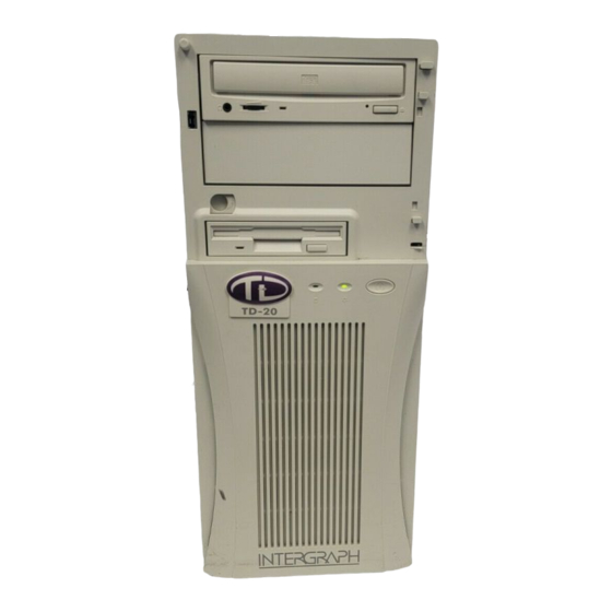
Starting the System Press the power switches on the base unit and the monitor to turn on power to the system. Refer to the following figure. CD-ROM Drive Door Lock Floppy Disk Drive Power Switch Power On LED Disk Access LED The system starts, and boots to a Setup screen or logon dialog for the operating system. -
Page 19: Setting Up The Software
Microsoft’s Installation Guide (Windows NT Workstation 3.51), Start Here (Windows NT Workstation 4.0), or Welcome to Windows 95. Documentation for expansion boards purchased from Intergraph (which may include a video display adapter, a network adapter, a SCSI adapter, and a PC Card adapter). - Page 20 Get and record the following information: Your name, and the name of your company or organization: For a system running Windows NT Workstation, the CD Key from the Windows NT Workstation CD case, or the Product ID Number from Start Here, the Installation Guide, or the registration card: For a system running Windows 95, the...
-
Page 21: Going Through Setup
Have several blank, formatted diskettes available to create backup diskettes containing system software. The Windows NT delivery media contain software and drivers for both Reduced Instruction Set Computing (RISC)- and Intel-based systems. When installing Windows NT distribution files, make sure to install them from the \ 386 directory (the Intel software directory) on the delivery media. -
Page 22: Using The Welcome Dialog
On a system running Windows 95: While Windows 95 files are being copied to the system, you are prompted for the Windows 95 Setup Boot Diskette. This occurs even if the Windows 95 boot diskette is already inserted in the floppy disk drive. Select OK to continue. Next, you are notified that the file could not be found on the Windows 95 MTMCDAI... -
Page 23: Creating A Repair Disk Or A Startup Diskette
QFE update software contains fixes for operating system problems or limitations on your Intergraph system, and is only shipped with the system if it is needed. If QFE update software is shipped with the system, you should create a QFE backup diskette for use if you have to re-install the operating system. -
Page 24: What Now
What Now? Refer to Chapter 3, “Configuring the System,” to configure the system for use. Refer to the online System Introduction for information on system features and controls. -
Page 25: Configuring The System
Windows NT Workstation 3.51. CAUTION Installing Service Pack 4 may affect removal of installed Intergraph software products. Microsoft has provided a fix for this, and Intergraph has included this fix in the Quick-Fix Engineering (QFE) update software delivered with the system. -
Page 26: Configuring A Dual-Screen Display (G95 Graphics)
Configuring a Dual-Screen Display (G95 Graphics) On a system set up for dual-screen G95 graphics (using two G95 video display adapters), the video display driver treats the combined display area of both screens as a single canvas that covers both screens. In this Full Canvas style, windows centered on the canvas are split between the two screens. -
Page 27: Correcting Video Display Problems
Dual Screen option. A multi-sync monitor is selected, but a monitor with different video timings (such as an Intergraph InterVue monitor) is connected to the system. Select the appropriate monitor type. The monitor selection is inappropriate for the multi-sync monitor attached to the system. -
Page 28: Configuring The Sound Processor
If the system has a microphone and speakers, you can use the operating system’s sound control programs to control them. Additional accessories for the on-board sound processor are available from the Intergraph Bulletin Board Service (IBBS) or from vendor bulletin boards pointed to by the IBBS. -
Page 29: Configuring The Scsi Adapter
Service Packs from Microsoft’s World Wide Web and FTP sites free of charge. CAUTION If Intergraph provides a Service Pack through the IBBS or with a product or system, it has been certified against Intergraph hardware as described in the announcement of its availability. -
Page 30: Scsi System Bios
From time to time, new versions of the system’s basic input/output system (BIOS) are made available on the Intergraph Bulletin Board Service (IBBS). You may want to update the system’s current BIOS with a new version to take advantage of fixes or enhancements. -
Page 31: Td-200 Bios
1 during boot to run BIOS Setup. Write down the setting for each parameter; then exit from BIOS Setup and let the system continue to boot. From the IBBS login, go to Intergraph Product Centers, Systems and Networking, File Libraries, and Delivered Drivers; select the operating system and hardware platform. - Page 32 Insert a diskette into the floppy disk drive. In the directory containing the files, run the program. This FLASHPROG INSTALL creates a boot diskette with the new BIOS file and the BIOS flash programming utility. After the program completes, leave the diskette in the floppy disk drive and INSTALL restart the system.
-
Page 33: What Now
If the system experiences operational problems after you restart it, reprogram the BIOS using the previous version of the BIOS that you saved to diskette. What Now? Refer to Chapter 4, “Operating Notes,” to learn things you may need to know when operating the system. -
Page 35: Operating Notes
4 Operating Notes Refer to the information in this chapter when operating your Intergraph TD-20 or TD-200 system. Starting and Stopping the System After you complete Setup and start the system for the first time, you can start and stop the system as needed. -
Page 36: Observing Operating Precautions
Observing Operating Precautions Observe the following precautions when operating the system: When restarting the system, use the operating system controls instead of the turning the power switch off and on. Use the power switch only when instructed, or as the last alternative for restarting the system. -
Page 37: Using The Audio Input Application (Td-200)
Using the Audio Input Application (TD-200) CAUTION The first time you use the Audio Input application for the on-board sound processor on a TD-200 system, do not start it by selecting Input in the Mixer program. This will disable the Audio Input application. -
Page 38: Booting From An External Scsi Disk Drive
In the Devices dialog, select Close. Restoring a Disabled COM2 Port If your system shipped from Intergraph with a network adapter and a PC Card adapter, serial port COM2 was disabled to provide system resources to use both of these devices. You can restore the disabled COM2 port for use if you disconnect the networking adapter or the PC Card adapter from the system. -
Page 39: Installing System Software
CD-ROM or on backup diskettes delivered with expansion boards. Driver software is routinely improved and updated. Check the Intergraph Bulletin Board Service (IBBS) and vendor bulletin boards frequently for new and updated drivers. -
Page 40: Windows Nt Workstation 4.0
Windows NT Workstation 4.0 Depending on your system’s configuration, you will need some or all of the following system software (on backup diskette or on the operating system CD-ROM) during installation: SCSI adapter driver G76, G95, or Intense 3D Pro video display driver Network adapter driver Sound processor driver Mouse driver... -
Page 41: Windows Nt Workstation 3.51
“Operating Notes.” You can install additional accessories for the sound processor, available from the Intergraph Bulletin Board Service (IBBS) or from vendor bulletin boards pointed to by the IBBS. As shipped from the factory, the system’s hard disk drive contains Windows NT Workstation Setup files in the 386 directory. -
Page 42: Windows 95
Perform any operational changes required for your system as described in Chapter 4, “Operating Notes.” You can install additional accessories for the sound processor, available from the Intergraph Bulletin Board Service (IBBS) or from vendor bulletin boards pointed to by the IBBS. Windows 95 Depending on your system’s configuration, you will need some or all of the following system... - Page 43 NOTE TD-20 and TD-200 systems have different sound processors and require different sound processor drivers. TD-20 systems use the Sound Blaster driver; TD-200 systems use the Crystal Audio driver. To install Windows 95: Insert the Windows 95 boot diskette in the floppy disk drive. Insert the Windows 95 CD-ROM in the CD-ROM drive.
-
Page 44: Updating The Operating System
Service Packs from Microsoft’s World Wide Web and FTP sites free of charge. CAUTION If Intergraph provides a Service Pack through the IBBS or with a product or system, it has been certified against Intergraph hardware as described in the announcement of its availability. -
Page 45: Expanding The System
6 Expanding the System Refer to the information in this chapter to expand your Intergraph TD-20 or TD-200 system. Adding External Peripheral Devices You can add external peripheral devices to the system in several ways: Insert a PC Card device in the optional PC Card slot. You can insert Type I and Type II devices in both slots, or a single Type III device in the bottom slot. -
Page 46: Opening The Base Unit
CAUTION If you do not use cables supplied by Intergraph, use shielded cables to prevent excessive electromagnetic interference (EMI). Intergraph cables are designed to reduce the amount of EMI produced by the system. Opening the Base Unit You must open the base unit to change internal system settings, and to change or add system components such as expansion boards, system memory, and internal peripheral devices. -
Page 47: Adding Expansion Boards
Adding Expansion Boards You can add Peripheral Component Interconnect (PCI), Plug-n-Play (PnP), and Industry Standard Architecture (ISA) expansion boards by installing them in the system’s expansion slots. The following illustrations show the location of the expansion slots on the system board. -
Page 48: Icu
ICU to a File Allocation Table (FAT) partition on your system’s hard disk drive. ICU installation will not work on an NTFS-only system because you cannot access NTFS partitions from the ICU boot diskette. Intergraph recommends creating a 10 MB FAT partition to allow for future growth of the ICU and its information database. -
Page 49: Td-200 Icu
ICU to a File Allocation Table (FAT) partition on your system’s hard disk drive. ICU installation will not work on an NTFS-only system because you cannot access NTFS partitions from the ICU boot diskette. Intergraph recommends creating a 10 MB FAT partition to allow for future growth of the ICU and its information database. -
Page 50: Adding System Memory
Adding System Memory You can add system memory by adding or replacing single inline memory modules (SIMMs) on the system board. The following illustrations show the four SIMM sockets on the system board, which can hold up to 256 MB of random-access memory (RAM). The computer supports the use of Extended Data Out (EDO), Error Checking and Correction (ECC), and Past Page Mode (FPM) dynamic RAM (DRAM) memory. - Page 51 NOTE System memory modules available from Inter graph have been certified for use with Intergraph computers at extremes of temperature and system load to ensure reliable performance. System memory modules available from other vendors may function improperly or unreliably in your Intergraph computer.
-
Page 52: Adding Internal Peripheral Devices
The system has the following available peripheral bays: Two 5.25-inch x 1.6-inch peripheral bays for devices accessible from outside the system. If you purchased a CD-ROM drive and a PC Card slot from Intergraph, they occupy these bays. - Page 53 The following figure shows the 3.5-inch internal peripheral bays, viewed from the left side of the base unit with the cover removed. The illustration shows three 1.0-inch high devices installed, each secured to the support bracket by four screws (two on each side). Support Bracket Screws (two each side)
-
Page 54: Adding Scsi Peripheral Devices
For more information on installing an internal peripheral device, refer to the documentation delivered with the peripheral device, the information posted on the device, or the appropriate System Board Manual. Adding SCSI Peripheral Devices On a system equipped with a Small Computer System Interface (SCSI) adapter and internal SCSI disk drives, a SCSI adapter board is installed in a Peripheral Component Interconnect (PCI) expansion board slot. -
Page 55: Isa Bus Interrupt (Irq) Assignments
ISA Bus Interrupt (IRQ) Assignments TD-20 System Resource System Resource Reserved (system timer) System CMOS/real-time clock Reserved (keyboard) Open Reserved (interrupt controller) Open Serial port COM2 (default) Open Serial port COM1 (default) Mouse port Audio or open Reserved (math coprocessor) Floppy disk controller Primary IDE controller or open Parallel port LPT1 (default) -
Page 56: Direct Memory Access (Dma) Channels
Direct Memory Access (DMA) Channels TD-20 Channel Assignment Channel Assignment Open DMA controller Audio or open Audio or open Floppy disk controller Open Open Open TD-200 Channel Assignment Channel Assignment Audio or open Reserved (cascade channel) Audio or open Open Floppy disk contoller Open Audio or parallel port (ECC/EPP) -
Page 57: Input/Output (I/O) Addresses
Input/Output (I/O) Addresses The following tables list a subset of the reserved I/O addresses. TD-20 Address (hex) Description 0000 - 000F DMA controller 0020 - 0021 Interrupt controller 0040 - 0043 System timer 0060 - 0060 Keyboard 0061 - 0061 System speaker 0064 - 0064 Keyboard... - Page 58 TD-200 Address (hex) Description 0000 - 000F DMA 1 0020 - 0021 Interrupt controller 1 002E - 002F I/O controller configuration registers 00A0 - 00A1 Interrupt controller 2 00C0 - 00DE DMA 2 0170 - 0177 Secondary IDE channel 01F0 - 01F7 Primary IDE channel 0200 - 0207 Audio / game port...
-
Page 59: Index
Index ISA expansion boards, 35 networking, 16 about this document, viii sound processor, 16 AC power, connecting to, 4 the PC Card adapter, 16 AC voltage switch, setting, 4 the SCSI adapter, 17 adding expansion boards, 35 video display, 13 adding external peripheral devices, connections AC power, 4... - Page 60 13, 30 Intergraph Bulletin Board Service, parallel port, 33 PC Card Intergraph FAXLink, xii operation, 25 Intergraph on the Internet, xii support, 25, 33 internal peripheral devices, 40 PC Card adapter, configuring, 16 InterSite Version Manager, 10 PCI expansion boards...
- Page 61 information for, 8 placing system components, 1 Plug-n-Play expansion boards preparing for, 7 adding, 35 Setup files (Windows 95), 10, 32 ports, 2, 3, 4, 26, 33 Setup files (Windows NT precautions Workstation), 9, 29 antistatic, 34 sound processor, configuring, 16 operating, 24 sound system volume, controlling Primary Top/Left dual-screen style...
- Page 62 Quick-Fix Engineering (QFE) updates, 7, 11 unpacking the system, 1 re-installing, 27 updates to the operating system, 17, system software sources Windows 95, 32 updating the BIOS, 18 Windows NT Workstation, 32 Version Manager, 10 TCP/IP networking information, 8 video display TD-20 Last Known Good, 15 cable connections, 3...
-
Page 63: Returned Goods Authorization (Rga) Form
Phone Mail Address Reason for Return NOTE All returned equipment MUST be shipped in original Intergraph packaging to obtain warranty service. WARNING Back up disk drives before returning equipment. Intergraph is not responsible for data lost during shipment or the repair process. -
Page 64: Warranty Procedure
Warranty Procedure Some malfunctioning equipment cannot be repaired in the field, and you must return it to Intergraph for repair. Follow these steps to obtain a Returned Goods Authorization (RGA) log number and return the malfunctioning equipment. Determine the serial number of the system. The serial number is located on the white bar code identification label on the back of the base unit. - Page 65 Repair Depot RGA No. ________________________ Intergraph Corporation 9805 Kellner Road Huntsville AL 35894 Repair Depot RGA No. ________________________ Intergraph Corporation 9805 Kellner Road Huntsville AL 35894 Repair Depot RGA No. ________________________ Intergraph Corporation 9805 Kellner Road Huntsville AL 35894...
Need help?
Do you have a question about the TD-20 and is the answer not in the manual?
Questions and answers