Lexmark X342N - Multi Function Printer Service Manual
Service manual
Hide thumbs
Also See for X342N - Multi Function Printer:
- Specifications (2 pages) ,
- User manual (105 pages) ,
- Troubleshooting manual (5 pages)
Table of Contents
Advertisement
Quick Links
Advertisement
Table of Contents

Subscribe to Our Youtube Channel
Related Manuals for Lexmark X342N - Multi Function Printer


Summary of Contents for Lexmark X342N - Multi Function Printer
- Page 1 Lexmark™ X340, X340n, and X342n 7003-XXX • Table of contents • Start diagnostics • Safety and notices • Trademarks • Index Lexmark and Lexmark with diamond design are trademarks of Lexmark International, Inc., registered in the United States and/or other countries.
- Page 2 Lexmark, Lexmark with diamond design, and MarkNet are trademarks of Lexmark International, Inc., registered in the United States and/or other countries. PCL® is a registered trademark of the Hewlett-Packard Company.
-
Page 3: Table Of Contents
7003-XXX Table of contents Notices and safety information ......... . vii Laser notice . - Page 4 7003-XXX Fax quality service check ............2-23 Diagnosing fax problems .
- Page 5 7003-XXX Scanner calibration ............. . 3-9 ATM menu .
- Page 6 7003-XXX Scanner flatbed cover removal ........... .4-48 Scanner top removal .
-
Page 7: Notices And Safety Information
7003-XXX Notices and safety information The following laser notice labels may be affixed to this printer as shown: Laser notice The printer is certified in the U.S. to conform to the requirements of DHHS 21 CFR Subchapter J for Class I (1) laser products, and elsewhere is certified as a Class I laser product conforming to the requirements of IEC 60825-1. - Page 8 7003-XXX Avisos sobre el láser Se certifica que, en los EE.UU., esta impresora cumple los requisitos para los productos láser de Clase I (1) establecidos en el subcapítulo J de la norma CFR 21 del DHHS (Departamento de Sanidad y Servicios) y, en los demás países, reúne todas las condiciones expuestas en la norma IEC 60825-1 para productos láser de Clase I (1).
- Page 9 7003-XXX Huomautus laserlaitteesta Tämä kirjoitin on Yhdysvalloissa luokan I (1) laserlaitteiden DHHS 21 CFR Subchapter J -määrityksen mukainen ja muualla luokan I laserlaitteiden IEC 60825-1 -määrityksen mukainen. Luokan I laserlaitteiden ei katsota olevan vaarallisia käyttäjälle. Kirjoittimessa on sisäinen luokan IIIb (3b) 5 milliwatin galliumarsenidilaser, joka toimii aaltoalueella 770 - 795 nanometriä.
- Page 10 7003-XXX Service Manual manuals4you.com manuals4you.com...
-
Page 11: Safety Information
7003-XXX Safety information • The safety of this product is based on testing and approvals of the original design and specific components. The manufacturer is not responsible for safety in the event of use of unauthorized replacement parts. • The maintenance information for this product has been prepared for use by a professional service person and is not intended to be used by others. - Page 12 7003-XXX Sicherheitshinweise • Die Sicherheit dieses Produkts basiert auf Tests und Zulassungen des ursprünglichen Modells und bestimmter Bauteile. Bei Verwendung nicht genehmigter Ersatzteile wird vom Hersteller keine Verantwortung oder Haftung für die Sicherheit übernommen. • Die Wartungsinformationen für dieses Produkt sind ausschließlich für die Verwendung durch einen Wartungsfachmann bestimmt.
- Page 13 7003-XXX Informació de Seguretat • La seguretat d'aquest producte es basa en l'avaluació i aprovació del disseny original i els components específics. El fabricant no es fa responsable de les qüestions de seguretat si s'utilitzen peces de recanvi no autoritzades. •...
-
Page 14: Preface
7003-XXX Preface This manual contains maintenance procedures for service personnel. It is divided into the following chapters: General information contains a general description of the printer and the maintenance approach used to repair it. Special tools and test equipment, as well as general environmental and safety instructions, are discussed. -
Page 15: General Information
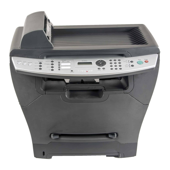
7003-XXX 1. General information The Lexmark™ X340, X340n, and X342n are MFPs that combine print, scan, copy, e-mail, and fax features into a single device designed for small workgroups. Maintenance approach The diagnostic information in this manual leads you to the correct field replaceable unit (FRU) or part. Use the error code charts, symptom index, and service checks to determine the symptom and repair the failure. -
Page 16: Supported Operating Systems
7003-XXX Supported operating systems The Lexmark X340, X340n, and X342n MFPs are compatible with following operating systems: • Microsoft Windows 2000 Professional • Microsoft Windows 2000 Server • Microsoft Windows 2000 Advanced Server • Microsoft Windows 2000 Server running Terminal Services •... -
Page 17: Media Trays And Supply Capacity
7003-XXX Media trays and supply capacity 7003-100 7003-050 7003-110 Item Lexmark X340 Lexmark X340n Lexmark X342n Available input trays 250-sheet tray Single-sheet manual feeder 550-sheet optional drawer Toner and photoconductor Toner cartridge yield 1,500 pages* (X 340 starter toner cartridge) -
Page 18: Types Of Print Media
7003-XXX Types of print media Ensure trays are properly loaded. Never mix media types within a tray. Input capacity Source Sizes Types Weight (sheets) Tray 1 , A5, JIS B5, Plain paper, 60–90 g/m 250 paper, letter, legal, transparencies, paper (16–24 lb) 50 labels (250-sheet tray) -
Page 19: Scanner Specifications
The MFP will display Scanner locked if the CCD is locked during POST. Note: Network scan is available only on the X340n, and X342n. The X340n and X342n are compatible with the Lexmark ScanBack utility. The ScanBack utility is bundled with the X342n. -
Page 20: Fax Specifications
Have any exposed adhesive when the flap is in the sealed position • Use only recommended paper. Refer to the Card Stock & Label Guide available on the Lexmark Web site at www.lexmark.com for more information about which paper provides optimum results for the current printing environment. -
Page 21: Tools
7003-XXX Tools The removal and adjustment procedures require the following tools and equipment: • Magnetic tip Phillips screwdrivers, large and small • Volt-ohmmeter General information... -
Page 22: Acronyms
7003-XXX Acronyms Autocompensator Mechanism (or paper feed) Automatic document feeder Analog front end ASIC Application Specific Integrated Circuit Complete Bill Of Material Charge coupled device Cyclic redundancy check DBCS Double byte character set DIMM Dual In-Line Memory Module Error correcting code Error correction mode External Network Adapter End of line... -
Page 23: Diagnostic Information
7003-XXX 2. Diagnostic information Start CAUTIONUnplug power from the MFP before connecting or disconnecting any cable, assembly, or electronic card. This is a precaution for personal safety and to prevent damage to the MFP. This chapter contains the codes and diagnostic tools to aid in providing corrective action for a malfunctioning MFP. -
Page 24: Symptom Tables
7003-XXX Symptom tables POST symptom table These symptoms may appear during the POST (Power-on Self Test). See “Power–On Reset (POR) sequence” on page 2-1 for the sequence when the MFP is turned on. POST symptom table Symptom Action The main motor, cooling fan, and “Controller card service check”... - Page 25 7003-XXX Symptom Action Toner on back of page “Toner on back of page” on page 2-33. Paper jams “Paper feed service checks” on page 2-29. Main motor noisy or does not “Main motor service check” on page 2-25. move Paper never picks “Paper never picks”...
-
Page 26: Understand The Operator Panel
7003-XXX Understand the operator panel Buttons Use the operator panel buttons to open a menu, scroll through a list of values, change MFP settings, and respond to MFP messages. Note: Buttons act on the information displayed on the second line of the operator panel. The following information describes the functions of each button:. - Page 27 7003-XXX Button Function Display panel 2 X 16 character backlit LCD(DBCS capable). Navigation Use the navigation buttons to navigate the MFP administrative menus. keys Press to navigate up the current active menu. Press to navigate down the current active menu. Press to select the currently displayed menu, or activate the currently displayed menu item.
-
Page 28: Using The Mfp Menus
7003-XXX Using the MFP menus Fax Defaults Content Original Size Copy Defaults Advanced Darkness Reports Darkness Auto Answer Rings Print Menus Content Behind PABX Distinct Ring Demo Page Number Dial Method Redials Network Setup Scale Fax Fwd Redial Wait Fax Call Log Collate Fax Footer Paper Source... -
Page 29: Messages And Error Codes
7003-XXX Messages and error codes Service error codes Service error codes are generally non-recoverable except in an intermittent condition when you can POR the MFP to temporarily recover from the error condition. Service error codes (9xx) Error Description Action Service Server firmware problem. -
Page 30: Non 9Xx Service Errors
7003-XXX Service error codes (9xx) (Continued) Error Description Action Toner Sensor The toner sensor is not operating properly, the developer drive assembly is not operating properly, or the toner cartridge is defective. See “Toner sensor service check” on page 2-38. Printhead Error—no Check for unplugged printhead (J12 on the controller card), faulty first hsync... -
Page 31: Paper Jam Messages
7003-XXX Paper jam messages Repeating jams or jam messages can be caused by any of the following: • Faulty pick solenoids or worn cams of the solenoids • Faulty flags or springs • Worn backup rollers at the reference guide •... -
Page 32: User Attendance Messages
7003-XXX User attendance messages Printer specific user attendance messages Message Explanation Change <source> This message displays when none of the MFP input sources contain the size <type><size> and/or type of media requested by the current print job. The following actions may be taken: •... - Page 33 7003-XXX Printer specific user attendance messages (Continued) Message Explanation The MFP determines the paper length is too short to print the formatted data. 34 Short Paper This occurs when the MFP does not know the actual paper size loaded in the tray.
- Page 34 7003-XXX Fax and scanner specific user attendance messages Message Explanation Change <source> This message is displayed during a fax operation when the Auto Reduce setting Plain <size> is “no”, and the media installed in the input tray is too small to print the fax being received.
-
Page 35: Sub Error Codes
7003-XXX Sub error codes The sub error codes are helpful troubleshooting a paper path problem. Each status byte has a different level of troubleshooting value for each area of the MFP. The following table displays up to 8 status bytes of data. Some or all of these bytes may be used to help diagnose a MFP problem. -
Page 36: Values
7003-XXX Values In the table below, the values for common variables are listed below: • media source 10=Multipurpose tray (MPT) 11=Tray 1 12=Tray 2 13=Tray 3 80=Duplex unit • media size 1=Letter 2=Legal 3=B5 4=A4 5=Executive 6=A5 7=Custom size 9=7¾ in. envelope A=#9 Envelope B=#10 Envelope C=8.661 in. - Page 37 7003-XXX Sub error codes (Continued) First 6 bytes sub Possible error code data Explanation error (xx can be any message value) The imaged page is not the expected page. 200.06 84 xx 20 x1 (x1=media size, x2=media source) Check the pass thru sensor to make sure it is operating properly. If no problem is found, it may still be necessary to try a new pass thru sensor.
- Page 38 7003-XXX Sub error codes (Continued) First 6 bytes sub Possible error code data Explanation error (xx can be any message value) 84 xx 2E Failed no gap jam recovery. Engine detected no gap at the manual feeder 200.22 sensor. An attempt was made to open the gap by stopping the feed rolls, but never saw the leading edge of the second page at the input sensor.
- Page 39 7003-XXX Sub error codes (Continued) First 6 bytes sub Possible error code data Explanation error (xx can be any message value) The exit sensor at the fuser is activated by a piece of media indicating 202.13 89 00 01 there is a piece of media in the machine during POST. Check for media in the exit of the fuser assembly or redrive assembly.
-
Page 40: Disconnects On The Controller Card
7003-XXX Disconnects on the controller card Always print a page from each paper source following a repair action. The following table is an aid to find a problem with a cable connection. Error or message Condition Check if cable is required to connectio Connector name and description... -
Page 41: Service Checks
7003-XXX Service checks Service checks which involve measuring voltages on the LVPS/HVPS (low voltage power supply/ high voltage power supply board) should be performed with the MFP positioned on its back side. Note: When you make voltage readings, always use frame ground unless another ground is specified. -
Page 42: Ccd Service Check
7003-XXX CCD service check Action If you are receiving a 942 error, check the home position sensor for dirt, and ensure that the sensor is properly connected to the CCD. Ensure that connectors J1 and J4 are properly connected. Inspect both ribbon cable connections on CCD for proper connection. -
Page 43: Controller Card Service Check
7003-XXX Controller card service check Action Controller card assembly Verify +24 V dc input from the LVPS/HVPS. • Turn the MFP off. • Disconnect the LVPS/HVPS cable from the controller card at J7. See “Controller card” on page 5-4 for more information. •... -
Page 44: Cover Interlock Switch Service Check
7003-XXX Cover interlock switch service check Note: Make sure a print cartridge assembly is installed and the cover closes all the way, engaging the cover open switch lever. Action Cover interlock switch Disconnect the cover interlock cable from the controller card at J13. Verify continuity between cable pin 1 and pin 2 with the door closed but not open. -
Page 45: 7003-Xxx
7003-XXX Fax quality service check Diagnosing fax problems Problem Solution No dial tone “Modem service check” on page 2-26. Ring tone volume for incoming faxes too low Replace controller card. Document does not feed in the ADF. “ADF service check” on page 2-19. -
Page 46: Hot Fuser Service Check
7003-XXX Fuser service check (continued) Action Unplug the MFP and disconnect the fuser lamp cable plug from the LVPS/HVPS board connector CN102. Check for continuity across the fuser lamp by checking across the connector pins. • If there is continuity, go to Step 1: Continuity. Lamp cable •... -
Page 47: Lvps/Hvps Service Check
7003-XXX LVPS/HVPS service check Action LVPS portion of board Fuses that open typically indicate a faulty LVPS/HVPS. Use the voltage meter to verify the appropriate voltage at the MFP end of the power cable. Remove the LVPS/HVPS assembly from the MFP. LVPS/HVPS Check continuity on the fuses. -
Page 48: Modem Service Check
7003-XXX Modem service check Action Modem Ensure the phone line is properly connected to the top RJ-11 jack of the modem and phone jack on the wall. Controller card Ensure the modem cable is properly connected to the J69 on the modem card and J69 on the controller card. -
Page 49: Operator Panel Service Check
7003-XXX Operator panel service check Inspect the operator panel cable for damage. Make sure the cable is plugged in securely. POR the MFP, and check each light for proper operation. Operator panel service check Action Operator panel Buttons Controller card Check connector J5, pin 5 for 3.3 V. -
Page 50: Paperpath Sensor Service Check
7003-XXX Paperpath sensor service check Action All sensors Check all the sensor flags for breakage or if they are jammed. Check all the sensors for dirt. MPF sensor Check pin 1 on connector J18 for +5V and pin 2 on J18 for +3.3 V.Pin 3 should be ground. -
Page 51: Paper Feed Service Checks
7003-XXX Paper feed service checks Paper jam error indication during POST Action Exit sensor If the exit sensor flag is not resting within the paper exit sensor during POST, the MFP displays a paper jam message. Make sure the flag is operating freely and is correctly installed. -
Page 52: Paper Occasionally Picks Or Picks Multiple Sheets At Once
7003-XXX Paper occasionally picks or picks multiple sheets at once Action Tray 1 Check tray for paper catch points. Tray 2 (option) If the sheet being fed stops momentarily, the ACM applies additional vertical force causing additional sheets to feed. Do not mix paper types. -
Page 53: Print Quality Service Checks
7003-XXX Print quality service checks Note: Ensure cover is closed tightly. A gap in the opening may allow light to expose the photoconductor resulting in a ‘dirty’ print. Using print quality test pages Blank page Action Toner cartridge (not a FRU) Remove the toner cartridge, and gently shake it to evenly distribute the toner. -
Page 54: Heavy Background
7003-XXX Heavy background Poor development or poorly charged toner particles cause excessive background. This is more noticeable as the toner cartridge nears end-of-life. Action Toner cartridge (not a FRU) Make sure the toner cartridge and PC Kit are correctly installed and PC Kit (not a FRU) the high voltage contacts are clean. -
Page 55: Light Print
7003-XXX Light print Action Toner cartridge (not a FRU) Make sure the toner cartridge and PC Kit are installed correctly and that the toner cartridge is not low on toner. If the problem continues, install a new toner cartridge. Recheck condition before replacing PC Kit if necessary. Check the transfer roll for signs of toner buildup and contamination. -
Page 56: Solving Print Quality Problems
MFP. • Change the media texture setting. If the setting is not in your driver, you can download the correct Lexmark setup utility from the Lexmark Web site at www.lexmark.com. The print is getting light but the •... - Page 57 7003-XXX Problem Action The Toner Low message is • Remove the toner cartridge, and gently shake it from side to side displayed. to redistribute the toner (6K cartridge only). • Replace the toner cartridge. Solid black areas on • Choose a different fill pattern in your software program. transparencies or white streaks •...
- Page 58 7003-XXX Problem Action The paper sticks together/MFP • Remove the paper from Tray 1 or the optional Tray 2, and fan it. feeds multiple sheets of paper. • Don’t overfill Tray 1 or the optional Tray 2 (see media capacities in the media types and sizes chart in the User’s Reference).
-
Page 59: Scan Quality Service Checks
7003-XXX Scan quality service checks Image unclear Problem Action Scanner not properly calibrated Perform scanner calibration. Go to “” on page 3-8. Dirt on flatbed glass or calibration Clean glass with isopropyl alcohol. reference plate Black page If the MFP can print normal pages from the host PC see “CCD service check”... -
Page 60: Toner Sensor Service Check
7003-XXX Toner sensor service check Action Toner sensor Try a different toner cartridge. If changing the toner cartridge doesn’t fix the problem, check pin 1 in J17 for +5V. Pin 3 is ground. If the voltage is present, replace the toner sensor. -
Page 61: Diagnostic Aids
7003-XXX 3. Diagnostic aids Accessing service menus Use the following key sequence to enter diagnostics mode. Note: The printer does not need a POR to enter diagnostics mode. Note: The X340, X340n, and X342n do not have a configuration menu. Diagnostics 1. -
Page 62: Diagnostics Mode
7003-XXX Diagnostics mode Available menu items Note: The tests display on the operator panel in the order shown: SERIAL NUMBER - Go to “Serial number” on page 3-3. String USB - Go to “USB” on page 3-3. PRINTER MODEL- Go to “Printer Model”... -
Page 63: Serial Number
7003-XXX SCANNER CALIBRATION - Go to “” on page 3-8. Restore Default ATM MENU - Go to “ATM menu” on page 3-9. Do not change these settings. FAX SETTINGS - Go to “Fax settings” on page 3-9. Fax Modulations Detect EOLs Autoprint T30 Log Print T30 Log Print CND Log... -
Page 64: Printer Model
7003-XXX Printer Model Printer model is used to indicate the model of the MFP. This menu item must be set after a new controller card is installed To set the printer model: Enter DIAGNOSTICS. Use UP or Down to scroll to Printer Model. Press Use Up or Down to scroll to the model type of MFP. -
Page 65: Fax Usage
7003-XXX Fax Usage Fax Usage is the second item displayed in the Count Reset menu. When Fax Usage is displayed, press the key to select the Fax Usage sub menu item. The following sequence is used for all Fax Usage sub menu settings. -
Page 66: Nvram Reset
7003-XXX NVRAM Reset The NVRAM reset menu item is used to reset the network settings in the MFP’s NVRAM. To reset the NVRAM, perform the following tasks: In the Network Menu, scroll to NVRAM Reset. Press to select NVRAM Reset. The MFP will display Are you sure? Yes=1, No=2. -
Page 67: Scanner Registration
7003-XXX Print a skew page to check the margins. The arrow on the top margin should be fully visible. Repeat steps 1 through 9 for Left Mrgn and Bottom Mrgn. Note: The margins for the top, left and bottom are properly set when the arrows on the four arrows are fully visible. -
Page 68: Using The Test Copy Page Rulers To Determine Correct Scanner Registration With Build 67 Firmware
7003-XXX Using the test copy page rulers to determine correct scanner registration with build 67 firmware The test copy sheet contains rulers that are used to determine the correct margin position. The following diagrams show where the margins for letter and A4 paper need to line up on the flatbed or ADF to determine correct scanner registration. -
Page 69: Scanner Calibration
7003-XXX Scanner calibration The scanner calibration menu item is used to restore the scanner calibration values to their default settings. To calibrate the scanner, perform the following steps: Use Up or Down to scroll to Scanner Calibration. Press to select Calibration from the diagnostics menu. Press The scanner automatically calibrates. -
Page 70: Print T30 Log
7003-XXX Print T30 Log This setting is used to print a T30 log which can be used to help second level support troubleshoot a FAX issue. To print a T30 log perform the following steps: Select Print T30 Log. Press The T30 log is printed. -
Page 71: Homologation Settings
7003-XXX Homologation settings Note: These settings should only be adjusted at the discretion of your second level support. Use the Print All item in the Homologation Settings menu to get a print out of the settings before calling your second level support center. - Page 72 7003-XXX 3-12 Service Manual manuals4you.com manuals4you.com...
-
Page 73: Repair Information
7003-XXX 4. Repair information Warning: Read the following before handling electronic parts. Handling ESD-sensitive parts Many electronic products use parts that are known to be sensitive to electrostatic discharge (ESD). To prevent damage to ESD-sensitive parts, follow the instructions below in addition to all the usual precautions, such as turning off power before removing logic cards: •... -
Page 74: Removal Procedures
7003-XXX Removal procedures Remove the toner cartridge and paper tray before removing other MFP parts. The toner cartridge should be protected from light while out of the MFP. We recommend disconnecting all external cables from the MFP to prevent damage during service. Unless otherwise stated, re-install the parts in reverse order of removal. -
Page 75: Left Side Cover Removal
7003-XXX Use your left hand to hold the fuser link at the cover joint while rotating the right side of the cover slightly away from the MFP to disengage the link. Remove the front access cover. Left side cover removal Open the front access cover to expose two screws (A) and the two latches (B) securing the left side cover. - Page 76 7003-XXX Remove the three screws (C) that secure the left cover to the rear cover. Release the latches with the right hand while applying opening force with the left hand. While pulling the left side cover away from the MFP, lift the left cover upwards to disengage it from the scanner top cover.
-
Page 77: Rear Cover Removal
7003-XXX Rear cover removal Remove the upper and lower right side covers. See “Upper right side cover removal” on page 4-8 more information. Remove the left side cover. See “Left side cover removal” on page 4-3 for more information. Remove the two screws (A) securing the cover. Open the rear door (rear exit tray). - Page 78 7003-XXX Push and release the tabs (B) on both sides of the rear cover. I Service Manual manuals4you.com manuals4you.com...
- Page 79 7003-XXX While lifting the scanner lid up, lift the rear cover, unhook it from the scanner top and the frame at the bottom and remove. Repair information...
-
Page 80: Upper Right Side Cover Removal
7003-XXX Upper right side cover removal Remove the lower right side cover. See “Lower right side cover removal” on page 4-10. Remove one screw (A) from the front and the two screws (B) on the rear side. Open the rear door (output tray). Service Manual manuals4you.com manuals4you.com... - Page 81 7003-XXX Swing the cover upwards and away from the MFP. Repair information...
-
Page 82: Lower Right Side Cover Removal
7003-XXX Lower right side cover removal Remove the screw(A) holding the lower right side cover. Release the latch (B) on the front of the lower right side cover. Swing the lower right side cover open. Lift the MFP up slightly, and disengage the lower hinge. Disengage the upper hinge. -
Page 83: Top Cover Removal
7003-XXX Top cover removal Remove the scanner assembly. See “Scanner base assembly removal” on page 4-51. Remove four screws (A) that secure the top cover to the printer frame. Remove two screws (B) at the front of the top cover just behind the access door. Lift and remove the top cover. -
Page 84: Card Cage Removal
7003-XXX Card cage removal Remove lower right cover. Go to “Lower right side cover removal” on page 4-10. Remove screw (A) securing the card cage to the frame. Press in metal tab and remove card cage. 4-12 Service Manual manuals4you.com manuals4you.com... -
Page 85: Controller Card Removal
7003-XXX Controller card removal Warning: Always touch a ground before touching the card. Warning: Handle the card by the edges. Note: Use part number 40X4828 for the X342n, and 40X2632 for the X340 and X340n. Remove the upper right cover. See “Upper right side cover removal”... - Page 86 7003-XXX Remove four screws (B) that secure the controller card to the metal side frame. Carefully lift the card and remove. Note: The scanner registration and calibration, as well as printer registration, must be set after replacing the controller card. Go to “Registration”...
-
Page 87: Cover Open Sensor Removal
7003-XXX Cover open sensor removal Open the lower right side cover. Remove the toroid from the group of cables located at the top of the controller card. Disconnect the cover open switch at J13 on the controller card and extract the cable. Use a small Phillips screwdriver to remove the screw (A) that secures the sensor to the printer frame. -
Page 88: Developer Drive Coupling Assembly Removal
7003-XXX Developer drive coupling assembly removal Remove the left side cover. See “Left side cover removal” on page 4-3. Carefully place the MFP on its right side. Protect the cover from marring. Remove four screws (A) in the gear train metal cover. Remove the gear train metal cover. -
Page 89: Exit Sensor Removal (On The Fuser)
7003-XXX Exit sensor removal (on the fuser) Remove the paper exit guide assembly. See “Paper exit guide assembly removal” on page 4-31 more information. Unplug the exit sensor at J10 on the controller card. Push the shaft (A) to the right using your right thumb against the inside gear surface and left index finger against the opposite end of the shaft. -
Page 90: Fan Removal
7003-XXX Remove the two screws (B) securing the fuser. Slide the fuser out just enough to access the screw holding the sensor. Remove the sensor and its attached cable. Observe the orientation of the flag and spring before replacing units. Fan removal Open the upper right side cover. -
Page 91: Feed Rollers (Autocompensator Tires) Removal
7003-XXX Remove the fan from the MFP. Feed rollers (autocompensator tires) removal Remove the paper tray. Remove the toner cartridge. Tilt the MFP onto its back. Remove old tires. Ensure the new tires are captured between the rims of the plastic hub. 4-19 Repair information... -
Page 92: Fuser Removal
7003-XXX Fuser removal Remove the paper exit guide assembly. See “Paper exit guide assembly removal” on page 4-31 more information. Remove the two screws (A) securing the fuser. Disconnect the thermistor cable at J15 and exit sensor at J10 on the controller card. Slide the fuser out far enough to expose and disconnect the AC cable connections. -
Page 93: Fuser Idle Gear Links Removal
7003-XXX Fuser idle gear links removal Remove the front access cover. See “Front access cover removal” on page 4-2 for more information. Remove the left side cover. See “Left side cover removal” on page 4-3. Place MFP on its right side. Protect the cover from being marred. Remove the four screws (A) securing the gear train cover. -
Page 94: Fuser Power Cable Removal
7003-XXX Fuser power cable removal Remove the LVPS/HVPS card. See “LVPS/HVPS card assembly removal” on page 4-26 for more information. Note: The cable can be reached without fully removing the card. Remove the rear cover. See “Rear cover removal” on page 4-5 for more information. -
Page 95: Input Roller Clutch And Lever Removal (Autocompensator Clutch)
7003-XXX Input roller clutch and lever removal (autocompensator clutch) Remove the left side cover. See “Left side cover removal” on page 4-3. Place the MFP on its right side. Protect the cover from being marred. Remove four screws (A) in the gear train metal cover. Remove the clip (B) from the shaft of the input roller clutch assembly. -
Page 96: Input Sensor #1 Removal
7003-XXX Input sensor #1 removal Remove the right side cover. See “Upper right side cover removal” on page 4-8 for more information. Disconnect the sensor cable at J20 on the controller card (front, near top of card). Carefully place the MFP on its back. Using a small shank screwdriver, remove the screw (A) behind the ACM (auto compensator) pivot that holds the paper sensor in place. -
Page 97: Input Sensor #2 (Manual Feed) Removal
7003-XXX Input sensor #2 (manual feed) removal Open the right side cover. See “Upper right side cover removal” on page 4-8 for more information. Disconnect the sensor cable at J18 on the controller card (front, top of card). Remove the paper tray. Carefully place the MFP on its back with the bottom of the MFP facing you. -
Page 98: Lvps/Hvps Card Assembly Removal
7003-XXX LVPS/HVPS card assembly removal Note: After installing the new power supply, ensure that the correct firmware setting for the power supply is set. See “Power supply ID” on page 3-4. Remove the cover extender (if installed), paper tray, and the rear cover. See “Rear cover removal”... -
Page 99: Lvps/Hvps To Controller Card Cable Removal
7003-XXX Move the cover so the connecting cables can be unplugged. Rotate the power supply assembly so the remaining cables can be removed. Remove the LVPS/HVPS card and cover. LVPS/HVPS to controller card cable removal Remove the LVPS/HVPS card. See “LVPS/HVPS card assembly removal”... -
Page 100: Manual Feed Clutch Assembly Removal
7003-XXX Manual feed clutch assembly removal Remove the left side cover. See “Left side cover removal” on page 4-3 Place the MFP on its right side. Protect the cover from being marred. Remove the four screws (A) in the gear train metal cover. Remove the clip (B) from the shaft of the pick up clutch assembly. -
Page 101: Network Card Removal
7003-XXX Network card removal Remove lower right side cover. Go to “Lower right side cover removal” on page 4-10. Remove the card cage. Go to “Card cage removal” on page 4-12. Disconnect the ground wire connecting the network card to the controller card. Remove the screw that secures the network card to the rear plate on the MFP frame. -
Page 102: Operator Panel Assembly Removal
7003-XXX Operator panel assembly removal Remove the operator panel overlay. Remove the 4 screws (A) from that secure the operator panel to the scanner base assembly. Lift the operator panel assembly up, and gently pull it away from the scanner top. 4-30 Service Manual manuals4you.com... -
Page 103: Paper Exit Guide Assembly Removal
7003-XXX Disconnect the operator panel cable. Remove the operator panel assembly. Paper exit guide assembly removal Remove the rear cover. See “Rear cover removal” on page 4-5 for more information. Remove the three screws (A) securing the exit guide. Remove the paper exit guide assembly. Reinstallation note: It may be necessary to rotate the gears to mesh with the fuser and drive gear. -
Page 104: Printhead Removal
7003-XXX Printhead removal Remove the top cover. See “Top cover removal” on page 4-11 for more information. Remove the toroid from the group of cables at the top of the controller card. Unplug the printhead cables at locations J11 and J12 on the controller card and on the printhead. Remove three screws (A) that secure the printhead to the cross brace, and lift the printhead out. -
Page 105: Transfer Roll Removal
7003-XXX Transfer roll removal Note: Handle the transfer roll as little as possible. Open the front access cover. Place a sheet of paper around the transfer roll to protect it. At the right side of the transfer roll, squeeze the holder arms with the left hand while lifting with the right. Stop when the holder is unlatched. -
Page 106: Transport Motor Cable Removal
7003-XXX Transport motor cable removal Remove the right cover. See “Upper right side cover removal” on page 4-8 for more information. Unplug the transport motor cable (XPRT) at J9. Remove the LVPS/HVPS card assembly. See “LVPS/HVPS card assembly removal” on page 4-26 more information. -
Page 107: Scanner Adf Paper Tray Removal
7003-XXX Scanner ADF paper tray removal Locate tabs (A) beneath the paper tray. Pull the tabs back, and remove the paper tray from the ADF assembly. 4-35 Repair information... -
Page 108: Scanner Adf Top Assembly Removal
7003-XXX Scanner ADF top assembly removal Remove the ADF paper tray. Go to “Scanner ADF paper tray removal” on page 4-35. Remove the ADF pick roll. Go to “Scanner ADF pick roll assembly removal” on page 4-39. Remove the ADF separator pad. Go to “Scanner ADF separator pad removal”... - Page 109 7003-XXX Pinch the tabs (C) that fasten the paper present sensor to the ADF top assembly. Remove the top half of the ADF assembly. 4-37 Repair information...
-
Page 110: Scanner Adf Top Cover Removal
7003-XXX Scanner ADF top cover removal Remove the ADF assembly. See “Scanner ADF assembly removal” on page 4-42. Lift the ADF top cover all the way back, and pull it away from the ADF unit. Scanner ADF separator pad removal Open ADF top cover. -
Page 111: Scanner Adf Pick Roll Assembly Removal
7003-XXX While pinching the green separator pad guide locks (B) inward, lift and remove the ADF separator pad out of the ADF unit. Scanner ADF pick roll assembly removal Open the ADF top cover. Open the green pick roll hinge (A) by pinching the hinge and gently pulling it down. 4-39 Repair information... - Page 112 7003-XXX Hold the ADF pickroll hinge down, and push the ADF pick roll assembly toward the rear of the ADF. Pivot the front of the ADF pickroll assembly to the right, and lift the ADF pick roll assembly out of the ADF unit.
-
Page 113: Scanner Adf Pick Roll Hinge Removal
7003-XXX Scanner ADF pick roll hinge removal Open the ADF top cover. Remove the ADF pick roll. assembly. See “Scanner ADF pick roll assembly removal” on page 4-39. Remove the screw (A) that secures the pick roll hinge to the ADF top cover. Note: The cover is removed for illustrative purposes only. -
Page 114: Scanner Adf Assembly Removal
7003-XXX Scanner ADF assembly removal Remove the two screws (A) that secures the ADF assembly to the flatbed cover. Open the ADF top cover. Remove the ADF paper tray assembly. Go to “Scanner ADF paper tray removal” on page 4-35. Remove two screws (B) that secure the top of the ADF assembly. - Page 115 7003-XXX Open the ADF assembly. Disconnect the ADF ground (C), and the ADF cable (D). 4-43 Repair information...
- Page 116 7003-XXX Disconnect the screw (E) holding the ADF cable. Remove the two inner screws that secure the ADF to the flatbed cover. Remove the ADF assembly. Note: The scanner registration and calibration must be set after replacing the ADF assembly. See “”...
-
Page 117: Scanner Adf Cable Removal
7003-XXX Scanner ADF cable removal Remove rear cover. See “Rear cover removal” on page 4-5. Disconnect the ADF cable from J3 on the controller card. Disconnect the ground wire (A). 4-45 Repair information... - Page 118 7003-XXX Remove the two screws (B) that secure the top of the ADF assembly. Open the ADF assembly. 4-46 Service Manual manuals4you.com manuals4you.com...
- Page 119 7003-XXX Disconnect the ground (C) and ADF cable (D). Remove the screw (E) and ADF cable clamp. Carefully remove the ADF cable from the ADF assembly. 4-47 Repair information...
-
Page 120: Scanner Flatbed Cover Removal
7003-XXX Scanner flatbed cover removal Remove the rear cover. See“Rear cover removal” on page 4-5. Disconnect the ADF cable from J3 on the controller card. Lift and remove the flatbed cover from the MFP. Scanner top removal Remove rear cover. See “Rear cover removal”... -
Page 121: Scanner Ccd Assembly Removal
7003-XXX Scanner CCD assembly removal Remove the scanner top. See“Scanner top removal” on page 4-48. Carefully remove the 18 and 20 pin ribbon cables (A) from the CCD. Gently remove the geared belt from the CCD. Note: Be careful to avoid touching the lamp in the CCD. 4-49 Repair information... - Page 122 7003-XXX Remove the screw (B) that secures the guide rod retainer. Remove the guide rod retainer. Lift the guide rod, and slide the CCD off the guide rod. Note: The scanner registration and calibration must be set after replacing the CCD assembly. See “”...
-
Page 123: Scanner Base Assembly Removal
7003-XXX Scanner base assembly removal Remove rear cover. See“Rear cover removal” on page 4-5. Remove the modem card. See “Modem card removal” on page 4-54. Disconnect the operator panel cable (A) from J5 on the controller card. Disconnect the 18 and 22 pin ribbon cables (B) from connectors J1 and J4 on the controller card. Disconnect the ADF cable from connector J3 on the controller card. - Page 124 7003-XXX Remove two screws (C) on the right side of the MFP that attach the scanner unit to the printer base. Do not discard the screws.I Locate the two pins (D) on the left side of the MFP that attach the scanner unit to the printer base. Do not discard the pins.
- Page 125 7003-XXX Pull the plastic retaining tab back, place a flat blade screwdriver in the notch on the metal pin. Remove the pin from the base. Repeat steps 8 and 9 for the second pin. Lift the scanner assembly from the printer base. 4-53 Repair information...
-
Page 126: Modem Card Removal
7003-XXX Modem card removal Remove upper right cover. See “Upper right side cover removal” on page 4-8. Disconnect the modem cable (A), modem speaker wire (B), and ground wire (C) from the modem card. Remove the other screw from the bottom of the modem card. While prying the rear cover back, slide the modem card down, and remove the modem card from the MFP. -
Page 127: Modem Speaker Assembly Removal
7003-XXX Modem speaker assembly removal Remove upper right side cover. Go to “Upper right side cover removal” on page 4-8. Remove operator panel. Go to “Operator panel assembly removal” on page 4-30. Remove the two screws (A) securing the modem speakers to the scanner base assembly. Disconnect the modem speaker cable from the modem card. - Page 128 7003-XXX 4-56 Service Manual manuals4you.com manuals4you.com...
-
Page 129: Locations And Connections
7003-XXX 5. Locations and connections Locations Front view Rear view Modem Rear Paper Power Exit Switch Locations and connections... -
Page 130: Adf
7003-XXX ADF Separator Pad ADF Paper Guides ADF Paper Tray ADF Separator Roller Service Manual manuals4you.com manuals4you.com... -
Page 131: Connections
7003-XXX Connections Power supply board Power supply board connections Conn Connects to # wires Wire colors CN102 Fuser Blue, white CN201 Controller card Black CN202 Charge roll Red, blue CN203 Developer Red, white, blue TAP201 Transfer roll Locations and connections... -
Page 132: Controller Card
7003-XXX Controller card Service Manual manuals4you.com manuals4you.com... -
Page 133: Controller Card Connections
7003-XXX Controller card connections Conn # Name Connects to # wires Wire colors J100 Tray 2 Tray 2 Red, yellow, orange, green, blue, grey J101 Paperfeed 2 red, 2 black solenoids HVPS/ Power 10 black LVPS Supplies XPRT Main motor Red, orange, green, blue, purple, white, grey, yellow Input sensor Red, white, black... -
Page 134: Modem Card
7003-XXX Modem card Conn# Connects to # wires Wire colors Controller card White Phone Service Manual manuals4you.com manuals4you.com... -
Page 135: Wiring Diagram
7003-XXX Wiring diagram Note: See the fold out wiring diagram in the back of this book for a large view. Locations and connections... -
Page 136: Controller Card Pin Assignments
7003-XXX Controller card pin assignments Note: Only J3, J69, J5, J1, and J4 pins are described in the following tables. The remaining connectors are described in the wiring diagram at the back of the manual. J3 ADF Pin # Signal AM_DIR AM_STEP PAPER_IN_P... -
Page 137: J 69 Modem
7003-XXX J 69 Modem Pin # Signal +3.3V +3.3V SYSDATA0 SYSDATA1 SYSDATA2 SYSDATA3 SYSDATA4 SYSDATA5 SYSDATA6 SYSDATA7 SYSADR0 SYSADR1 SYSADR2 SYSADR4 SYSADR5 SYSADR6 FAXINT SYS_WR SYS_RD FAX_CS2 MOD_RDY MOD_PRES RESET_TO_MODEM Locations and connections... -
Page 138: J5 Operator Panel
7003-XXX J5 Operator panel Pin # Signal UI_DATA_1 UI_DATA_0 UI_DATA_2 VCC3 UI_DATA_3 UI_DATA_5 UI_DATA_4 UI_DATA_6 VDD_UI UI_DATA_7 LCDRW VDD_UI LCDE LCDRS KBRD NC_SPKR KBWR 5-10 Service Manual manuals4you.com manuals4you.com... -
Page 139: J1 Flatbed Motor
7003-XXX J1 Flatbed motor Pin # Signal VDD5_MOTOR HMSEN V_24_MOTOR_FB FM_MS2 FM_MS1 FM_STEP FM_DIR FM_SLEEP FM_RESET VREF_SW1 VREF_SW2 V24_LAMP 5-11 Locations and connections... -
Page 140: J4 Ccd Module
7003-XXX J4 CCD module Pin # Signal CCD_SW1 VOB_ODD VOG_EVEN1 VOB_EVEN2 +12V 5-12 Service Manual manuals4you.com manuals4you.com... -
Page 141: Preventive Maintenance
7003-XXX 6. Preventive maintenance Printer engine The Lexmark X340, X340n and X342n printer engines do not require preventive maintenance. Scanner The ADF pick pad (40X2404/40X3499) should be replaced every 20,000 pages, and the ADF pick roller (40X2401) should be replaced every 60,000 pages. - Page 142 7003-XXX Service Manual manuals4you.com manuals4you.com...
-
Page 143: Parts Catalog
PP: (Parts Packet) in the parts description column indicates the part is contained in a parts packet. • Model information used in the parts catalog. Machine type Description and model 7003-100 Lexmark X340 7003-050 Lexmark X340n 7003-110 Lexmark X342n Parts catalog... -
Page 144: Assembly 1: Covers
7003-XXX Assembly 1: Covers Service Manual manuals4you.com manuals4you.com... - Page 145 7003-XXX Assembly 1: Covers Asm- Part Units/ Units/ Description Index number mach 40X1354 ACM and front door springs 40X2423 Front cover assembly 40X2422 Rear cover assembly 40X2421 Base top cover assembly 40X2425 Upper right side cover 40X2426 Lower right side cover 40X2433 Optional drawer 2 assembly (no tray) 40X2432...
-
Page 146: Assembly 2: Scanner
7003-XXX Assembly 2: Scanner Service Manual manuals4you.com manuals4you.com... - Page 147 7003-XXX Assembly 2: Scanner Asm- Part Units/ Units/ Description Index number mach 40X2400 ADF top cover 40X2402 Pick roll hinge 40X2620 ADF top assembly 40X2629 ADF assembly 40X2404 Pick roll pad 40X3499 High friction pick roll pad 40X2406 ADF input tray assembly 40X2407 ADF extension assembly 40X2405...
- Page 148 7003-XXX Assembly 2 (continued): Scanner Service Manual manuals4you.com manuals4you.com...
-
Page 149: Assembly 3: Electronics
7003-XXX Assembly 3: Electronics Service Manual manuals4you.com manuals4you.com... - Page 150 7003-XXX Assembly 3: Electronics Asm- Part Units/ Units/ Description Index number mach 3–1 40X1303 Laser/mirror print assembly, X340, X340n, X342n 40X1300 Fuser assembly, 110 V 40X1301 Fuser assembly, 220 V 40X1302 Fuser assembly, 100 V 40X1325 Exit sensor assembly 40X1333 Miscellaneous cable assemblies Note: Do not use the included LVPS/HVPS cable.
-
Page 151: Assembly 4: Frame
7003-XXX Assembly 4: Frame 7-10 Service Manual manuals4you.com manuals4you.com... - Page 152 7003-XXX Assembly 4: Frame Asm- Part Units/ Units/ Description Index number mach 3–1 40X1334 Paper exit guide assembly 40X2822 Transfer, roll, bearings, gear, spring 40X2429 Legal extender cover 40X1353 Screws, miscellaneous (actual size) TP2NC-3.0+6P-Ni (2) M3.0*0.5+6P-Ni,2 Washer (2) MT3.0*0.5+6PF-Ni (5) TP2NC-3.0+6PF-Ni (4) 40X4731 ASM, Pick arm...
-
Page 153: Assembly 5: Miscellaneous
7003-XXX Assembly 5: Miscellaneous Asm- Part Units/ Units/ Description Index number mach 12A2405 USB cable, packaged 7376595 Field location package assembly 40X0289 Power cord, 1.8M (straight)—USA, Canada 40X0278 Power cord, 6 foot (straight)—Europe and others 40X0288 Power cord, 6 foot—Argentina 40X0271 Power cord, 6 foot—United Kingdom 40X0275... - Page 154 7003-XXX Assembly 2 (continued): Scanner Asm- Part Units/ Units/ Description Index number mach 40X2698 X 340–X340n Operator panel overlay (Norwegian) 40X2714 X 342n Operator panel overlay (Norwegian) 40X2699 X 340–X340n Operator panel overlay (Swedish) 40X2715 X 342n Operator panel overlay (Swedish) 40X2700 X 340–X340n Operator panel overlay (Finnish) 40X2716...
-
Page 155: Index
7003-XXX Index Numerics cover open sensor 4-15 removal 2xx paper jams –?? 2-10 2-11 3x—9x attendance messages – 9xx service errors –?? developer drive coupling assembly 4-16 removal diagnostics menu abbreviations ATM menu accessing service menus count reset acronyms fax usage ADF assembly page count parts catalog... - Page 156 7003-XXX 4-26 service error codes removal 2-14 sub errors LVPS?HVPS to controller card cable 2-10 4-27 user attendance messages removal ESD-sensitive parts exit sensor maintenance approach 4-17 removal manual feed extender cover 4-28 clutch assembly removal 4-25 input sensor #2 print media types and sizes manual feed clutch 4-18...
- Page 157 7003-XXX 7-10 4-48 frame flatbed cover 7-11 4-54 frame modem card 4-55 how to use modem speaker assembly 7-10 4-30 options operator panel assembly 4-51 scanner scanner base assembly 4-48 scanner 4-33 post symptoms transfer roll power-on reset (POR) power-on self test (POST) ii-xi safety information print media...
- Page 158 7003-XXX 2-33 light print 2-32 partial blank image 2-32 poor fusing of image 2-33 toner on back of page 2-33 white or black lines 2-38 toner sensor 2-38 transfer roll service error codes service menus X340⁄ 342n special tools specifications description description photoconductor capacity...
-
Page 159: Part Number Index
7003-XXX Part number index Description Page 12A2405 USB cable, packaged - - - - - - - - - - - - - - - - - - - - - - - - - - - - - - - - - - - - - - - - - - - - - - - - - - - - - - - - - - 7-12 40X0270 Power cord, 1.77M (straight)—Japan - - - - - - - - - - - - - - - - - - - - - - - - - - - - - - - - - - - - - - - - - - - - - - -... - Page 160 7003-XXX 40X2413 Silver flatbed stud - - - - - - - - - - - - - - - - - - - - - - - - - - - - - - - - - - - - - - - - - - - - - - - - - - - - - - - - - - - - - 40X2415 Scanner base assembly - - - - - - - - - - - - - - - - - - - - - - - - - - - - - - - - - - - - - - - - - - - - - - - - - - - - - - - - - 40X2416...
- Page 161 7003-XXX 40X2721 Operator panel overlay (Korean network) - - - - - - - - - - - - - - - - - - - - - - - - - - - - - - - - - - - - - - - - - - - - - 40X2822 Transfer, roll, bearings, gear, spring - - - - - - - - - - - - - - - - - - - - - - - - - - - - - - - - - - - - - - - - - - - - - - - - 7-11...
- Page 162 7003-XXX Service Manual manuals4you.com manuals4you.com...
Need help?
Do you have a question about the X342N - Multi Function Printer and is the answer not in the manual?
Questions and answers