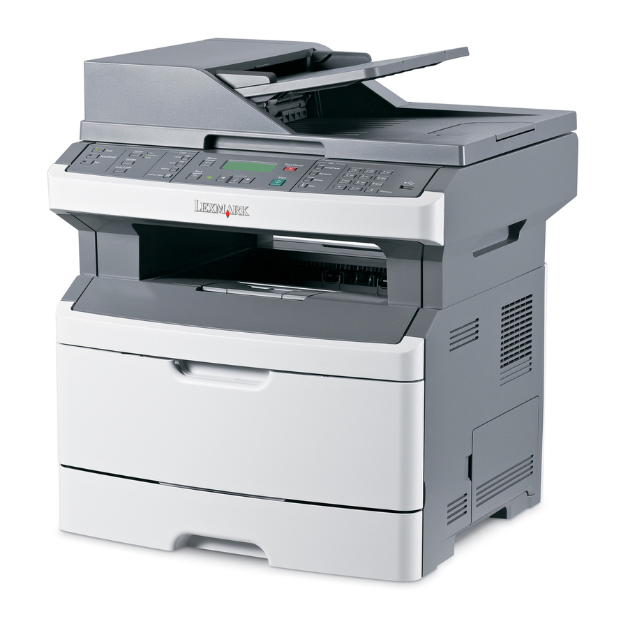
Lexmark X264dn Service Manual
Monochrome laser printers
Hide thumbs
Also See for X264dn:
- Specifications (6 pages) ,
- Brochure & specs (6 pages) ,
- Reference manual (3 pages)
Table of Contents
Advertisement
Quick Links
Lexmark
• Table of contents
• Start diagnostics
• Safety and notices
• Trademarks
• Index
Revision: January 10, 2014
™
X264dn, X363dn, X364dn, X364dw
Lexmark and Lexmark with diamond design are
trademarks of Lexmark International, Inc., registered
in the United States and/or other countries.
7013-235
7013-432
7013-436
7013-43W
Advertisement
Table of Contents

Subscribe to Our Youtube Channel
Related Manuals for Lexmark X264dn


Summary of Contents for Lexmark X264dn
- Page 1 X264dn, X363dn, X364dn, X364dw 7013-235 7013-432 7013-436 7013-43W • Table of contents • Start diagnostics • Safety and notices • Trademarks • Index Lexmark and Lexmark with diamond design are trademarks of Lexmark International, Inc., registered in the United States and/or other countries.
- Page 2 Lexmark, Lexmark with diamond design, and MarkVision are trademarks of Lexmark International, Inc., registered in the United States and/or other countries. Optra Forms is a trademark of Lexmark International, Inc.
-
Page 3: Table Of Contents
7013-XXX Table of contents Notices and safety information ......... . . ix Laser notice . - Page 4 7013-XXX Printer symptom table ............2-24 Scan/fax /copy symptom table .
- Page 5 7013-XXX Input sources ..............3-5 Print Quality Pages (Prt Quality Pgs) .
- Page 6 7013-XXX Panel Menus ..............3-27 PPDS Emulation .
- Page 7 7013-XXX Duplex removal ..............4-16 Duplex ADF rear cover removal .
- Page 8 7013-XXX Assembly 6: Power cords ............7-12 Index .
-
Page 9: Notices And Safety Information
7013-XXX Notices and safety information The following laser notice labels may be affixed to this printer. Laser notice The printer is certified in the U.S. to conform to the requirements of DHHS 21 CFR Subchapter J for Class I (1) laser products, and elsewhere is certified as a Class I laser product conforming to the requirements of IEC 60825-1. - Page 10 7013-XXX Avisos sobre el láser Se certifica que, en los EE.UU., esta impresora cumple los requisitos para los productos láser de Clase I (1) establecidos en el subcapítulo J de la norma CFR 21 del DHHS (Departamento de Sanidad y Servicios) y, en los demás países, reúne todas las condiciones expuestas en la norma IEC 60825-1 para productos láser de Clase I (1).
- Page 11 7013-XXX Laserilmoitus Tämä tulostin on sertifioitu Yhdysvalloissa DHHS 21 CFR Subchapter J -standardin mukaiseksi luokan I (1) - lasertuotteeksi ja muualla IEC 60825-1 -standardin mukaiseksi luokan I lasertuotteeksi. Luokan I lasertuotteita ei pidetä haitallisina. Tulostimen sisällä on luokan IIIb (3b) laser, joka on nimellisteholtaan 5 mW:n galliumarsenidilaser ja toimii 770 - 795 nanometrin aallonpituuksilla.
- Page 12 7013-XXX Avís sobre el Làser Segons ha estat certificat als Estats Units, aquesta impressora compleix els requisits de DHHS 21 CFR, apartat J, pels productes làser de classe I (1), i segons ha estat certificat en altres llocs, és un producte làser de classe I que compleix els requisits d’IEC 60825-1.
- Page 13 7013-XXX xiii Notices and safety information...
- Page 14 7013-XXX Service Manual...
-
Page 15: Safety Information
7013-XXX Safety information CAUTION This product contains a lithium battery. THERE IS A RISK OF EXPLOSION IF THE BATTERY IS REPLACED BY AN INCORRECT TYPE. Discard used batteries according to the battery manufacturer’s instructions and local regulations. • The safety of this product is based on testing and approvals of the original design and specific components. - Page 16 7013-XXX Sicherheitshinweise • Die Sicherheit dieses Produkts basiert auf Tests und Zulassungen des ursprünglichen Modells und bestimmter Bauteile. Bei Verwendung nicht genehmigter Ersatzteile wird vom Hersteller keine Verantwortung oder Haftung für die Sicherheit übernommen. • Die Wartungsinformationen für dieses Produkt sind ausschließlich für die Verwendung durch einen Wartungsfachmann bestimmt.
- Page 17 7013-XXX Informació de Seguretat • La seguretat d'aquest producte es basa en l'avaluació i aprovació del disseny original i els components específics. El fabricant no es fa responsable de les qüestions de seguretat si s'utilitzen peces de recanvi no autoritzades. •...
-
Page 18: Preface
7013-XXX Preface This manual contains maintenance procedures for service personnel. It is divided into the following chapters: General information contains a general description of the printer and the maintenance approach used to repair it. Special tools and test equipment, as well as general environmental and safety instructions, are discussed. -
Page 19: Conventions
7013-XXX Conventions Note: A note provides additional information. Warning: A warning identifies something that might damage the product hardware or software. There are several types of caution statements: CAUTION A caution identifies something that might cause a servicer harm. CAUTION This type of caution indicates there is a danger from hazardous voltage in the area of the product where you are working. - Page 20 7013-XXX Service Manual...
-
Page 21: General Information
7013-XXX 1. General information The Lexmark™ X364dw, X364dn, X363dn, and X264dn are monochrome laser printers designed for single users or small workgroups. Maintenance approach The diagnostic information in this manual leads to the correct field replaceable unit (FRU) or part. Use the error code charts, symptom index, and service checks to determine the symptom and repair the failure. -
Page 22: Overview Of The Operator Panel
7013-XXX Overview of the operator panel The operator panel is divided into three sections: • Selections and settings area • Display area • Keypad area Selections and settings contains ten buttons (Copy, Scan/Email, Fax, Content, Darkness, Duplex/2-sided, Copies, Scale, Options, and Address book) and three lights (Text, Text/Photo, and Photo) that light up to display the chosen content option. -
Page 23: Specifications
7013-XXX Specifications Memory 7013-235 7013-432 7013-436 7013-43W Item Lexmark X264dn Lexmark X363dn Lexmark X364dn Lexmark X364dw Standard memory 64MB 128MB 128MB 128MB Maximum memory 64MB 128MB 128MB 128MB Optional memory 16MB 32MB 64MB 128MB 256MB 512MB Standard flash memory Maximum flash memory... -
Page 24: Print Quality Settings
7013-XXX Print quality settings 7013-235 7013-432 7013-436 7013-43W Item Lexmark X264dn Lexmark X363dn Lexmark X364dn Lexmark X364dw Image enhancement technology (IET) ✔ ✔ ✔ ✔ 2 Bits/pel ✔ ✔ ✔ ✔ 4 Bits/pel Print resolution ✔ ✔ ✔ ✔ 300 dpi ✔... -
Page 25: Compatibility And Connectivity
7013-XXX Compatibility and connectivity 7013-235 7013-432 7013-436 7013-43W Item Lexmark X264dn Lexmark X363dn Lexmark X364dn Lexmark X364dw Datastreams ✔ ✔ ✔ ✔ PCL 6 emulation ✔ ✔ ✔ ✔ PostScript level 3 emulation ✔ ✔ ✔ ✔ NPAP ✔ ✔... -
Page 26: Media Trays And Supply Capacity
7013-XXX Media trays and supply capacity 7013-235 7013-432 7013-436 7013-43W Item Lexmark X264dn Lexmark X363dn Lexmark X364dn Lexmark X364dw Standard input sources ✔ ✔ ✔ ✔ Integrated 250-sheet tray ✔ ✔ ✔ 50-sheet MP feeder ✔ 1-sheet manual feed slot Optional input sources ✔... -
Page 27: Types Of Print Media
7013-XXX Types of print media Note: Ensure trays are properly loaded. Never mix media types within a tray. Source Sizes Types Weight Input capacity* (sheets) Input tray 1 A4, A5, A6,JIS¹-B5, Plain paper, 60-90 g/m² • 150 paper letter, legal, executive, transparency, •... - Page 28 7013-XXX Source Sizes Types Weight Input capacity* (sheets) Duplex A4, letter, legal, oficio Plain paper, 60-90 g/m² • 250 paper (Mexico), folio recycled, bond, • 550 paper (16-24 lb) letterhead, preprinted, colored paper, light paper, heavy paper, custom type [x] Automatic document A4, A5, JIS¹-B5, letter, Accepts any media type supported by the print engine...
-
Page 29: Digital Imaging Specifications
7013-XXX Digital imaging specifications General specifications ADF Scan speed Simplex ADF - Up to 22 ppm ADF Document handling ADF input capacity - 50 sheets ADF output capacity - 50 sheets ADF document width - 4.9” (125mm) to 8.5” (216mm) ADF document length - 5”... -
Page 30: Scan And Copy Specific Specifications
Scan to PC via network TWAIN • Scan to PC using Web applet • Scan to E-Mail • Scan to USB (X364 models only) • Lexmark Scan Center Multiple copies 999 copies maximum Reduce/Enlarge (copy only) -25% to 400% 1-10 Service Manual... -
Page 31: Fax Specifications
7013-XXX Fax specifications Phone network connectivity Phone networks types supported PSTN or analog PABX (RJ-11) ITU COMPATIBILITY Group 3/ECM Standard Resolution 8 x 3.85 pels/mm (200X100dpi) (204x98) Fine 8 x 7.7 pels/mm (200X200dpi) (204x196) Superfine 11.8 x 11.8 pels/mm(300x300 dpi) (204x391) Ultrafine 15.7 x 15.7 pels/mm (400x400 dpi) (408x391) Coding... -
Page 32: Tools
7013-XXX Tools The removal and adjustment procedures require the following tools and equipment: • Spring hook • Needle nose pliers • Volt-ohmmeter • #1 and #2 Phillips screwdriver • Slotted screwdriver Acronyms Alternating Current Autocompensator Mechanism (or paper feed) Automatic document feeder Analog front end All-In-One Automatic Paper Size... - Page 33 LASER Light amplification by stimulated emission of radiation Liquid crystal display Liquid Crystal Module Laser Diode Light emitting diode Long edge feed Lexmark Embedded Solution (applications) Laser Scanning Unit Low Voltage LVPS Low voltage power supply Magenta Megabyte Motor Driver Control...
- Page 34 7013-XXX PIXEL Picture element Printer Job Language Power-on reset POST Power-on self test PPDS Personal Printer Data Stream Pages per minute PQET Print Quality Enhancement Technology Peoples' Republic of China Parallel Synchronous Communications Position Sensing Device Participating Standards Organization Pulse Width Modulation Random access memory RFID Radio frequency identification...
-
Page 35: Diagnostics Information
7013-XXX 2. Diagnostics information Start CAUTION: Unplug power from the printer before connecting or disconnecting any cable, assembly, or electronic card. This is a precaution for personal safety and to prevent damage to the printer. This chapter contains the codes and diagnostic tools to aid in providing corrective action for a malfunctioning printer. -
Page 36: Overview Of The Operator Panel And Menus
7013-XXX Overview of the operator panel and menus Understanding the operator panel The printer operator panel has a four-line, back lit, grayscale display that can show both graphics and text. The Mode selection, job setup, Back, and Menu buttons are located to the left of the display, the navigation buttons are located below the display, and the start buttons, stop button, and numeric pad are located to the right of the display. - Page 37 7013-XXX Number Part Button Function Stop/Cancel button Stops/cancels all printer activity Redial/Pause button • Press once to cause a two- or three-second dial pause in a fax number. Redial/Pause Redial/Pause • Press to redial a fax number Keypad Enters numbers, letters, or symbols on the LCD display Front USB port Scans to a flash drive or prints supported file types Note:...
- Page 38 7013-XXX Number Part Button Function Select button Accepts menu selections and settings Left arrow button Scrolls to the left on the display screen Indicator light Indicates printer status: • Off: the printer is off • Blinking green: the printer is warming up, processing data, or printing •...
-
Page 39: Diagram Of The Printer Menus
7013-XXX Diagram of the printer menus Not all menus or selections will be available on all models or in all situations. These are accessed through the driver. Paper Menu Job Menu Finishing Menu Utilities Menu Paper Source Reset Printer Duplex Quick Demo Paper Size Print Menus... -
Page 40: Messages And Error Codes
7013-XXX Messages and error codes User attendance messages The printer control panel displays messages describing the current state of the printer and indicates possible printer problems that must be resolved. This topic provides a list of all printer messages, explains what they mean, and tells how to clear the messages. - Page 41 7013-XXX User status and attendance messages (continued) User primary message Explanation Load Manual Printer does not detect media meeting the description <custom string> in the <custom string> single sheet feeder (manual feeder). The following actions can be taken: • Load paper and the job continues. •...
- Page 42 7013-XXX User status and attendance messages (continued) User primary message Explanation 35 RES Save Off This message displays when the printer lacks sufficient memory to enable Deficient Memory Resource Save. This message usually indicates the user has allocated too much memory for one or more of the printer link buffers;...
- Page 43 7013-XXX User status and attendance messages (continued) User primary message Explanation 39 Complex Page This message is displayed when a page is too complex to print. The following actions can be taken: • Press Select ( ) to clear the message and continue printing. The job may not print correctly.
- Page 44 7013-XXX User status and attendance messages (continued) User primary message Explanation 56 Standard USB This message may appear when data is sent to the printer across a USB port, but Port Disabled the port is disabled. Note: Once the error is displayed the first time, reporting of further errors is suppressed until the printer is reset or menus are entered.
-
Page 45: Cartridge Error Messages
7013-XXX Cartridge error messages Error Description Action Invalid refill Replace the cartridge. Missing or defective cartridge Unsupported print cartridge Paper jam error codes (200-series) Note: The Event log (See “Event Log” on page 3-15) will list any of these errors that have occurred. Repeating jams or jam messages can be caused by any of the following: •... - Page 46 7013-XXX Error Description Action 200.12 Media detected at manual feeder sensor when not Carefully remove the tray and notice if the leading expected. Possible causes include user insert of media edge of the media is pointed upward and out of the when motor is running or pre-staged media in the tray.
- Page 47 7013-XXX Error Description Action 200.27 Printhead Driver: Mirror motor fell out of lock condition Check the printhead. See “Printhead service after the media at the input sensor–more time elapsed check” on page 2-43. since the printhead than the expected stable lock time, but less than the printhead jitter-stable specification.
- Page 48 7013-XXX Error Description Action 201.02 Exit sensor never made by leading edge of page. Also Remove the PC kit and paper or debris at the input known as internal jam. sensor. 201.03 Video never started on the page at the input sensor Check the printhead.
- Page 49 7013-XXX Error Description Action 231.00 Duplex jam while reversing into the device Open the rear cover and look for obstructions between the rear cover ribs, the fuser exit rollers, and below. The media entering the duplex passes 231.01 Duplex sensor never made by leading edge reversing outside the exit roller while the media exiting the into the duplex.
- Page 50 7013-XXX Error Description Action 242.16 Failed to feed from tray 2. Pages in the paper path Remove Tray 2 and inspect for obstruction in the have been flushed to the output bin. paper path. Check the pick tires for wear or paper dust.
-
Page 51: Service Error Codes
7013-XXX Service error codes Service error codes are generally non-recoverable except in an intermittent condition when the printer can be put into POR to temporarily recover from the error condition. Error Description Action 8xx.xx Scanner service errors 840.01 Scanner disabled: the scanner is disabled and cannot be Enter the configuration menu, and re-enable the Scanner used. - Page 52 7013-XXX Error Description Action Scanner Failure: general mechanical failure detected “CCD service check” on page 2-46. 843.02 Scanner Failure: pick roller engage failure 843.03 Scanner Failure: pick roller disengage failure 843.04 Scanner failure: lamp failure 844.yy Front scan module output level error 844.00 Front scan module lamp level too low: front Mono 844.01...
- Page 53 7013-XXX Error Description Action Modem failure: the Configuration ID bit that describes Replace the controller board. See “Controller 847.00 the device’s modem doesn’t match the actual modem board service check” on page 2-26. installed in the device. Fax storage: the amount of flash storage available on 847.01 the device is too small.
- Page 54 7013-XXX Error Description Action Toner service errors 929.00 Toner sensor error Remove the toner cartridge, and shake it Try a different toner cartridge, if possible. If the error persists, then replace the toner level sensor. See 929.01 No home window “Toner level sensor removal”...
- Page 55 7013-XXX Error Description Action 954.xx NVRAM chip failure with system part. Replace the controller board. See “Controller board service check” on page 2-26. 955.xx The code ROM or NAND flash failed the Cyclic Redundancy Check or the NAND experienced an uncorrectible multi-bit failure.
- Page 56 7013-XXX Error Description Action 978.xx Bad checksum while programming network port Call the next level of support. 979.xx Flash parts failed while programing network port Other errors 980.xx Engine experiencing unreliable communication with the Call the next level of support. specified device 981.xx Engine protocol violation detected by the specified...
-
Page 57: Symptom Tables
7013-XXX Symptom tables POST symptom table Symptom Action The main motor, cooling fan, and fuser do not come “Cover interlock switch service check” on page 2-27. POST completes, but the LCD does not come on. “Operator panel service check” on page 2-31. -
Page 58: Printer Symptom Table
7013-XXX Printer symptom table Symptom Action Fan noisy or fan not working. “Cooling fan service check” on page 2-27. Fuser parts melted. “LVPS/HVPS service check” on page 2-29. Toner not fused to the media. See“Fuser service check” on page 2-29 “Solving print quality problems”... -
Page 59: Scan/Fax /Copy Symptom Table
7013-XXX Scan/fax /copy symptom table Symptom Action 840.xx scanner error “840.xx service check” on page 2-44. ADF will not duplex (Duplex ADF only) “ADF Duplex service check” on page 2-51. ADF skew “ADF feed errors service check” on page 2-50. Multiple pages feed into ADF Documents wont feed into ADF Scanner makes buzzing noise on startup or... -
Page 60: Service Checks
7013-XXX Service checks Service checks which involve measuring voltages on the LVPS/HVPS (low voltage power supply/ high voltage power supply board) should be performed with the printer positioned on its back side. Note: When making voltage readings, always use frame ground unless another ground is specified. -
Page 61: Cooling Fan Service Check
7013-XXX Controller board service check (continued) Action Verify main power to controller board With the printer off, unplug the LVPS/HVPS cable at J22 on the controller board. Verify grounds on pins 10, 12, 14, 16 and 18 for both the cable and the controller board. If any of these grounds are incorrect, then check the cable for continuity. -
Page 62: Dead Machine Service Check
7013-XXX Dead machine service check CAUTION: Check the AC line voltage. The voltage should be within the following limits: • 100 V ac (volts alternating current)-127 V ac for the 110 V printer • 200 V ac-240 V ac for the 220 V printer Action Unplug the printer. -
Page 63: Fuser Service Check
7013-XXX Fuser service check When toner is partially fused to the media, it is usually caused by low fuser temperature. The line voltage to the printer must be within the following limits: • 100 V ac-127 V ac for the 110 V model printer •... -
Page 64: Main Motor Service Check
7013-XXX Main motor service check Action Turn off the printer, and unplug the main motor cable at J19. Turn on the printer, and check for the following voltages at J19: J19 pins Voltages Pins 1-4, 6 Approx. 5 V dc Main motor gear drive Pins 7-9 18 V dc-24 V dc... -
Page 65: Operator Panel Service Check
7013-XXX Operator panel service check Inspect the operator panel cable for damage. Make sure the cable is plugged in securely. Run POST, and check each light for proper operation. See “Power–On Self Test (POST) sequence” on page 2-1. LCD Operator panel service check Action Operator panel (LCD) Lights... -
Page 66: Media Never Picks
7013-XXX Media never picks Action Paper feed (pick tires) tray 1 Open the left cover, and verify that the solenoids and clutches are functioning Paper feed (pick tires) tray 2 when an attempt is made to feed the media. Media drive ASM Make sure the rubber tires on the ACM are installed and clean. -
Page 67: Media "Trees," Wrinkles, Stacks Poorly, Or Curls
7013-XXX Media “trees,” wrinkles, stacks poorly, or curls Action Fuser This problem is most likely due to a worn backup roll. It causes the printer to run hotter than required for the media being printed. Excessive heat can cause media treeing problems, poor stacking, or curl. -
Page 68: Networking Service Check
Have the network administrator verify that the device is using the correct SSID, and wireless security protocols. For more network troubleshooting information, consult the Lexmark Network Setup Guide. Step... - Page 69 7013-XXX Step Questions / actions Try using a different ethernet cable. Problem resolved Go to step 14. Did this remedy the situation? Have the network administrator check the Replace the controller Contact the network network drop for activity. board. See “Controller administrator.
-
Page 70: Print Quality Service Checks
7013-XXX Print quality service checks Note: Ensure the cover closes tightly. A gap in the opening may allow light to expose the photoconductor, resulting in a ‘dirty’ print. Extreme environmental conditions, temperatures, and humidity will affect the print quality. Using print quality test pages To help isolate print quality problems, like streaking, print test pages using the print quality test pages. -
Page 71: Black Page
7013-XXX Black page Note: Incorrect laser exposure or incorrect charging of the photoconductor causes an all black page. Always verify the same results from a different print cartridge assembly and developer before proceeding. Action Toner electrodes (not Check the three rearward electrodes below the toner cartridge assembly for contamination, a FRU) damage, or a short to ground. -
Page 72: Partial Blank Image/White Spots (No Repeating Pattern)
7013-XXX Partial blank image/white spots (no repeating pattern) Action Toner cartridge (not a Remove the toner cartridge assembly, and gently shake the assembly to evenly distribute FRU) the toner. Check to make sure that the laser light path is not blocked. If toner cartridge is low, then try a new one. -
Page 73: Light Print
7013-XXX Light print Action Toner cartridge (not a Make sure the toner cartridge and PC Kit are installed correctly and that the toner cartridge FRU) is not low on toner. If the problem continues, then install a new toner cartridge. Recheck condition before replacing PC Kit, if necessary. -
Page 74: Solving Print Quality Problems
7013-XXX Solving print quality problems Note: Refer to the print defects guide at the end of the manual for repeating defects. Print quality problems Problem Cause/action Light or blurred Light print characters. “Light print” on page 2-39. The toner cartridge may be getting low on toner: •... - Page 75 7013-XXX Print quality problems (continued) Problem Cause/action Toner smears or rubs • Toner is not being fused to the paper. Replace the fuser. off the page. • Change the media texture setting in the driver. If special media is being used, such as card stock or labels, then be sure to select the correct media type.
- Page 76 7013-XXX Print quality problems (continued) Problem Cause/action The printer is on and • Make sure the USB cable is not damaged and is firmly plugged into the connector on indicates ready, but the back of the printer. nothing prints. • Make sure the toner cartridge assembly is installed properly. •...
-
Page 77: Printhead Service Check
7013-XXX Print quality problems (continued) Problem Cause/action Unexpected • Ensure correct printer driver is being used. characters print, or • Select hex trace mode to determine what the problem is. characters are • Restore factory defaults. missing. • Make sure the USB cable or USB cable is firmly plugged in at the back of the printer. Jobs are not printing, •... -
Page 78: Tray 2 Service Check
7013-XXX Tray 2 service check Action Tray 2 Turn the printer off. Separate the printer from Tray 2. Turn the printer on and check the voltages on connector J28 on the controller board. See the wiring diagram at the end of the service manual, or “Controller board connector pin values”... - Page 79 7013-XXX Step Questions / actions Replace the ADF cable. POR the machine Go to step 7. Stop. Problem solved. into configuration mode. Go to the disable scanner menu item. See “Disable Scanner” on page 3-31. Select “Enable ADF/FB -Enabled and press to save the change.
-
Page 80: Black Or Blank Page Copy Service Check
7013-XXX Black or blank page copy service check Step Questions / actions Print a menu page, or a page from the host. “Networking service Go to step 2. Is the page black? check” on page 2-34 Is the copy an ADF scan? Go to step 3. -
Page 81: Flatbed Home Position Service Check
7013-XXX Flatbed home position service check Step Questions / actions POR the MFP. Does the CCD move and Problem solved. Go to step 2. return to the home position? Perform the home position sensor test. See Go to step 3. Go to step 5. -
Page 82: Adf Cover Open Service Check
7013-XXX ADF cover open service check Step Questions / actions Is the ADF cover properly closed? Go to step 3. Go to step 2. Close the ADF cover. Issue resolved Go to step 3. Does the problem go away? Perform the ADF cover open sensor test. Go to step 4 Go to step 8. -
Page 83: Adf Paper Jam Service Check
7013-XXX ADF paper jam service check Note: This service check should be used if the paper feeds and jams in the ADF. If the paper is not feeding into the ADF see “ADF feed errors service check” on page 2-50. Step Questions / actions If the ADF is multi-feeding, check for dirt on... -
Page 84: Adf Feed Errors Service Check
7013-XXX ADF feed errors service check Step Questions / actions If the ADF is multi-feeding, check for Clean them with a lint free Replace the separator pad and dirt on the ADF separator pad and cloth and isopropyl alcohol. ADF pick roll. ADF separator rollers. -
Page 85: Adf Duplex Service Check
7013-XXX ADF Duplex service check Step Questions / actions Perform sensor 1, and sensor 2 Go to step 2. Go to step 3. sensor tests. See “Scanner Tests” on page 3-17. Are the sensors working properly? Check the ADF sensor actuators to Go to step 3. -
Page 86: Modem / Fax Card Service Check
7013-XXX Modem / fax card service check Step Questions / actions Is the phone line properly connected to the Go to step 3. Go to step 2. modem card and the wall jack? Properly connect the phone line to the Problem resolved. -
Page 87: Fax Transmission Service Check
7013-XXX Fax transmission service check Note: Before performing this service check, verify that the correct country code for the MFP is selected. This setting must match the country in which the MFP is used to transmit and receive faxes. If the setting is wrong, the modem settings can be changed in the Fax/SE menu. - Page 88 7013-XXX Step Questions / actions Adjust the “Transmit Level” setting in the SE Stop. Problem resolved. Go to your second-level of menu. Press **411 to enter the SE menu, support. See “Escalating a enter Modem settings, and select “Transmit fax issue to second-level Level”.
-
Page 89: Fax Reception Service Check
7013-XXX Fax reception service check Step Questions / actions Is the phone line properly connected to the Go to step 3. Go to step 2. modem card and the wall jack? Properly connect the phone line to the Problem resolved. Go to step 3. - Page 90 7013-XXX Step Questions / actions Go to the Administrator menu. Enter the Fax Go to step 18. Go to step 19. settings - Analog Fax Settings submenu. Verify the remote device number is not in the Banned Fax List user setting. Is the remote device number in the banned fax list? Remove the remote number from the...
-
Page 91: Escalating A Fax Issue To Second-Level Support
7013-XXX Escalating a fax issue to second-level support Before contacting the second-level support, go to the SE menu on the MFP and generate a Fax error file. This file contains machine settings information and debug information that will help second-level support determine the cause of a failure. - Page 92 7013-XXX 2-58 Service Manual...
-
Page 93: Diagnostic Aids
7013-XXX 3. Diagnostic aids This chapter explains the tests and procedures to identify printer failures and verify repairs have corrected the problem. Menu key combinations There are different test menus that can be accessed during POR to identify problems with the printer. Configuration Menu 1. -
Page 94: Diagnostics Menu (Diag Menu)
7013-XXX Diagnostics Menu (Diag Menu) Note: Tray 2 refers to the 650-sheet tray located in the 650-sheet Duo Drawer assembly. Diagnostics menu structure When the Diagnostics mode is entered, each Diagnostics main menu item displays on the operator panel. When a diagnostic test is selected from the main menu, a sub menu displays, and each individual test displays in the order shown. - Page 95 7013-XXX Diagnostics mode tests (continued) BASE SENSOR TEST “Base Sensor Test” on page 3-12. Front Door Input Fuser Exit Standard Bin DEVICE TESTS “Printer Setup” on page 3-12. Flash Test PRINTER SETUP Defaults “Defaults” on page 3-12. Perm Page Count “Page Counts”...
-
Page 96: Registration
7013-XXX Registration The Registration menu settings adjusts the margins. To set print registration, select REGISTRATION from the Diagnostics menu. The following will display: REGISTRATION Top Margin Note: Pressing will display one margin setting per line below the REGISTRATION header. The REGISTRATION settings and values are: Setting Value Top Margin... -
Page 97: Print Quick Test Page
7013-XXX Print Quick Test Page Print a Quick Test page to verify that the REGISTRATION margin values are set appropriately. The Quick Test page consists of the following: • Alignment diamonds • Horizontal lines used for skew adjustment • General device information (current page count, installed memory, etc.) •... -
Page 98: Miscellaneous Tests
7013-XXX Miscellaneous Tests Motor Detect This test initiates an automatic motor detection process that should be performed whenever the controller board is replaced. To run Motor Detect: Select MISC TESTS in the Diag Menu, and press Select ( Remove Cartridge. Press Select appears. Select Motor Detect. -
Page 99: Hardware Tests
7013-XXX Hardware Tests Panel Test This test verifies the operator panel LCD function. To run the Panel Test: Select Hardware Tests from Diag Menu, and press Select ( Select Panel Test, and press Select ( The Panel Test continually executes. Press Stop ( ) to cancel the test. -
Page 100: Cache Test
7013-XXX To stop the test early, turn off the printer. CACHE Test The CACHE Test is used to verify the processor cache is functioning properly. Select Hardware Test in Diag Menu, and press Select ( Select CACHE Test, and press Select ( The printer displays: CACHE Test Testing…... -
Page 101: Duplex Tests
7013-XXX Duplex Tests Quick Test (duplex) This test prints a duplex version of the Quick Test that can be used to verify the correct placement of the top margin on the back side of a duplex page. Note: Before you set the duplex top margin, be sure to set the registration. See “Registration”... -
Page 102: Top Margin (Duplex)
7013-XXX Top Margin (duplex) This setting controls the offset between the first scan line on the front of the duplex page and the first scan line on the back of the page. Therefore, be sure to set the top margin in REGISTRATION before setting the duplex top margin. -
Page 103: Input Tray Tests
7013-XXX Input Tray tests Feed Tests This test allows you to observe the paper path of media as it passes through the printer. Any installed input tray can be tested. The pages fed through the printer are blank. To run the Feed Test: Select INPUT TRAY TESTS from Diag Menu, and press Select ( Select Feed Tests, and press Select ( Select the tray to be tested. -
Page 104: Base Sensor Test
7013-XXX Base Sensor Test These tests allow you to verify the correct functioning of the front door, input, and output sensors. Select Base Sensor Test from Diag Menu, and press Select ( Select the sensor you want to test, and press Select ( The following test are available: Sensor Value... -
Page 105: Serial Number
7013-XXX Serial Number The serial number can only be viewed. It cannot be changed. To view or change the serial number: Select PRINTER SETUP from DIAGNOSTICS, and press Select ( Select Serial number, and press Select ( Press Back ( to return to PRINTER SETUP. -
Page 106: Enable Edge To Edge Copy
7013-XXX Enable Edge to Edge Copy This setting is set to either on or off. Off is the default setting. Reset Fuser Count Resets the fuser count value to zero. The Event Log records each time that a user executes the Reset Fuser Count operation. -
Page 107: Automatic Darkness Adjustment (Auto Dark Adj)
7013-XXX Automatic Darkness Adjustment (Auto Dark Adj) This setting attempts to optimize the amount of toner used when printing with a specific operating point. Each time this setting executes, the printer performs the following: • Calibrates its toner density sensor •... -
Page 108: Print Log
7013-XXX Print Log Additional diagnostic information is available when you print the event log from DIAGNOSTICS rather than CONFIG MENU. The Event Log printed from DIAGNOSTICS includes: • Detailed printer information, including code versions • Time and date stamps • Page counts for most errors •... -
Page 109: Scanner Tests
7013-XXX Scanner Tests ASIC Test This test initiates a scan of the scanner ASIC’s memory. While this test is executing ASIC Test Running is displayed. When the test is complete, ASIC Test Passed is displayed if the ASIC memory is okay. ASIC Test Failed is displayed if the test fails. Press the Back or Stop buttons to clear the display message. - Page 110 7013-XXX ADF paper present sensor test This test should be used if the ADF fails to feed paper when a scan is performed. To test this sensor, perform the following steps: In the sensor test menu, press to scroll to the ADF paper present test. ).
- Page 111 7013-XXX FB Cover closing sensor test This test verifies the functionality of the FB cover closed sensor. To test this sensor, perform the following steps: In the sensor test menu, press to scroll to the FB Cover closing sensor test. ).
- Page 112 7013-XXX Sensor 1 test This test verifies the functionality of scan sensor 1. To test this sensor, perform the following steps: In the sensor test menu, press to scroll to the Sensor1 test. ). Starting Test displays. Sensor 1: Closed displays. Press Select ( Lift the ADF top cover, and close the ADF cover sensor by pressing down on the ADF sensor actuator (A) with a small, flatblade screwdriver.
- Page 113 7013-XXX Sensor2 test This test verifies the functionality of scan sensor 2. To test this sensor, perform the following steps: In the sensor test menu, press to scroll to the Sensor 2 test. ). Starting Test displays. Sensor 2: Closed displays. Press Select ( Lift the ADF top cover, and close the ADF cover sensor (A) by pressing down on the ADF sensor actuator with a small flatblade screwdriver.
-
Page 114: Exit Diags
7013-XXX EXIT Diags Press Select ( ) to exit Diag Menu. The printer performs a power-on reset and returns to normal mode. 3-22 Service Manual... -
Page 115: Printhead Assembly Electronic Adjustment
7013-XXX Printhead assembly electronic adjustment A step-by-step process to align a new printhead. Note: Before aligning the printhead electronically, first align the printhead mechanically, if needed. See “Printhead assembly mechanical adjustment” on page 3-24. Enter the Diagnostics menu. See “Diagnostics Menu (Diag Menu)” on page 3-2. -
Page 116: Printhead Assembly Mechanical Adjustment
7013-XXX Print the Quick Test page again, and check that the darkest line in the center graph is equal to zero. If it is, then check to see if the left, top, and bottom margins are detected. If it is not, then repeat step 5. Note: The alignment of the left margin positions the plane to the right or left. - Page 117 7013-XXX If the grid lines of the right flap align below the corresponding lines on the left flap, then adjust the printhead clockwise relative to the printer and recheck. (See the left side of the figure below.) If the grid lines of the left flap align below the corresponding lines of the right side, then adjust the printhead counterclockwise.
-
Page 118: Configuration Menu
7013-XXX Configuration Menu Available tests The tests display on the operator panel in the order shown for all models. Configuration menu USB Scan to Local “USB Scan to Local” on page 3-26. Prt Quality Pgs “Prt Quality Pages” on page 3-26. -
Page 119: Reports
7013-XXX Reports Menu Settings Page Print the menu settings pages to list the customer settings and to verify printer options are installed correctly. It is helpful to print the customer settings before you restore factory defaults or make major changes. To print the menu settings: Select Reports from the Config Menu, and press Select ( Select Menu Settings Page, and press Select (... -
Page 120: Demo Mode
7013-XXX Demo Mode Lets marketing personnel or merchandisers demonstrate the printer to potential customers by printing the demo page. Selections include Deactivate (default) and Activate. Select Deactivate to turn Demo Mode off; or select Activate to turn Demo Mode on. Factory defaults Sets the majority of printer values back to their factory default settings. -
Page 121: Min Copy Memory
7013-XXX Min Copy Memory This setting allocates the amount of DRAM memory to be used for storing copy jobs in the queue. 25, 35, 50, 80 and 100 MB are the available settings. To adjust the minimum copy memory, perform the following steps: In the configuration menu, scroll to the MinCopy Memory item, and press Use the to increase or decrease the setting’s value. -
Page 122: Fb Edge Erase
7013-XXX FB Edge Erase This menu item sets the size, in millimeters, of the no print area around a flatbed scan job. Copy jobs will use the setting or two millimeters, whichever is larger. To adjust the flatbed edge erase setting, perform the following steps: In the Configuration menu, select the FB Edge Erase menu item. -
Page 123: Disable Scanner
7013-XXX Use the to increase or decrease the setting’s value. Note: Each button press moves the margin values one pixel in the respective direction. Press to accept the value. Scroll to Top Edge, and press Use the to increase or decrease the setting’s value. Note: Pressing moves the margin up, and pressing moves the margin down. -
Page 124: Font Sharpening
7013-XXX Font Sharpening This setting is used to set a text point size value below which the hig- frequency screens will be used when printing data. This setting affects only PCL, PostScript and PDF emulators. Settings are in the range of 0–150 (24 is the default). For example, if the value is set to 24, then all fonts sized 24 points or less use the high-frequency screens. -
Page 125: Se Menu
7013-XXX SE Menu Note: This is not the Fax SE menu. To enter the Fax SE menu, press **411 from the Ready screen. Note: This menu should be used as directed by second-level support. Print SE Menus General Copyright - Displays copyright information. Optra Forms mode - On or off Code Revision Info Network Code Level - Displays network code level... -
Page 126: Paper Jams
Have any exposed adhesive when the flap is in the sealed position • Use only recommended media. Refer to the Card Stock & Label Guide available on the Lexmark Web site at www.lexmark.com for more information about which media provides optimum results for the current printing environment. -
Page 127: Understanding Paper Jam Codes And Locations
7013-XXX Understanding paper jam codes and locations 200-202 paper jams CAUTION The fuser and the area inside of the printer near the fuser may be hot. Allow the surface to cool before removing media from this area. Remove the paper tray from the printer. If there is a paper jam, then remove the paper jam. -
Page 128: 231 Paper Jam
7013-XXX 231 paper jam CAUTION The fuser and the area inside of the printer near the fuser may be hot. Allow the surface to cool before removing media from this area. Open the front door. Open the rear door. Remove the paper jam. Close the rear door. -
Page 129: 234 Paper Jam
7013-XXX 233 paper jam Remove the paper tray from the printer. Locate the lever shown, and pull it down to release and to remove the jammed sheets. Reinstall the paper tray, and press 234 paper jam A single jam or multiple jams are in the duplex area of the printer when the printer is turned on. To locate and remove the jammed sheets, complete all steps in “231 paper jam”... -
Page 130: 242 Paper Jam
7013-XXX 242 paper jam Remove the optional paper tray from the printer. Remove the paper jam. Reinstall the optional paper tray, and press 3-38 Service Manual... -
Page 131: Paper Jam
7013-XXX 251 paper jam A sheet of paper or specialty media failed to feed completely from the multipurpose feeder. Part of it may still be visible, If it is visible, then gently pull the jammed sheets from the front of the multipurpose feeder. If the sheet is not visible, then complete the following steps: Open the front door, and remove the photoconductor kit and toner cartridge. -
Page 132: 290-294 Paper Jams
7013-XXX 290-294 paper jams Remove all original documents from the ADF. Open the ADF cover. Unlock the separator roll. Remove the separator roll. 3-40 Service Manual... -
Page 133: 291.Xx Adf Paper Jams
7013-XXX Remove the jammed paper. Reinstall the separator roll, and lock into place. Close the ADF cover, and press 291.xx ADF paper jams Remove all original documents from the ADF input tray. Remove the ADF input tray. See “ADF input tray removal” on page 4-8. -
Page 134: Updating The Printer Firmware
7013-XXX Updating the printer firmware Using a USB flash drive The device firmware can be updated from a USB flash drive on models equipped with a USB direct interface on the operator panel. The printer must be in a Ready state in order to perform the code update. A MFP that is in Invalid Code Mode cannot be updated via the USB thumbdrive Warning: Before performing a firmware update on the device, contact your second level support to confirm, or obtain the correct code. -
Page 135: Using The Host Computer To Update The Mfp Firmware Over Usb
7013-XXX Using the host computer to update the MFP firmware over USB Note: This procedure uses the program, USB Flash. USButil is a command line USB flash utility that can also be used to update firmware from a host computer via USB. To use any USB flashing utility, the MFP must be installed on the host computer so a USB virtual printer port can be established on the host computer. -
Page 136: Scanner Theory
7013-XXX Scanner theory Duplex ADF The following illustration shows the paper path, rollers, and sensors used in the duplex ADF. The duplex ADF enables the user to create duplex scans automatically, eliminating the need to stop the scanning process to flip the media being duplicated. The ADF uses a step motor, and a series of sensors to determine the media’s position in the paper path during the scan process. - Page 137 7013-XXX 6. When the ADF scan sensor is actuated the paper advances to the scan area. While the paper is advancing to the scan area, the ADF motor generates pulses which are stored in an on-board counter. These counts along with the ADF scan sensor ensure that the media is travelling at the correct speed through the scan area.
- Page 138 7013-XXX 3-46 Service Manual...
-
Page 139: Repair Information
7013-XXX 4. Repair information Warning: Read the following before handling electronic parts. Handling ESD-sensitive parts Many electronic products use parts that are known to be sensitive to electrostatic discharge (ESD). To prevent damage to ESD-sensitive parts, follow the instructions below in addition to all the usual precautions, such as turning off power before removing logic cards: •... -
Page 140: Removal Procedures
7013-XXX Removal procedures Note: • Remove the toner cartridge and media tray before removing other printer parts. The toner cartridge should be protected from light while out of the printer. • We recommend disconnecting all external cables from the printer to prevent damage during service. •... -
Page 141: Acm Pick Tire Roller Removal
7013-XXX ACM pick tire roller removal Place the printer on its side. Note: Be careful to not mar the finish of the printer. Open the duplex jam door just far enough to pull out the ACM pick tires. Warning: Open the duplex door only far enough to remove the ACM pick tires. If the door is opened too far, then it can become disengaged and interfere with the paper tray. -
Page 142: Adf Removal
7013-XXX ADF removal Tilt the flatbed cover to the upright position. Lift the ADF up and away from the flatbed. While lifting the ADF, use a flatblade screwdriver to pry open the two tabs of the Simplex, or the three tabs (A) of the Duplex on the bottom of the ADF cover. - Page 143 7013-XXX Carefully pull the ADF cable and grommet (D) away from the ADF assembly. Lift the ADF to an upright position. Use a screwdriver to release the left hinge (E) from the flatbed unit. Repair information...
- Page 144 7013-XXX Remove the ADF assembly. Note: Perform the ADF registration procedure after installing the new ADF unit. See “Scanner Manual Registration” on page 3-30. Service Manual...
-
Page 145: Adf Cable Removal
7013-XXX ADF cable removal Remove the flatbed. See “Flatbed removal” on page 4-24. Remove the ground screw (A). Disconnect the ADF cable from J4 on the controller board. Un-route the ADF cable from the scanner tub frame assembly. Remove the ADF cable. Repair information... -
Page 146: Adf Input Tray Removal
7013-XXX ADF input tray removal Firmly grasp the ADF input tray on both sides. Pull the ADF input tray out of the ADF. Service Manual... -
Page 147: Adf Scanner Assembly Removal
7013-XXX ADF scanner assembly removal Remove the rear door and cover. See “Rear door and cover removal” on page 4-69. Remove the front scanner cover. See “Front scanner cover removal” on page 4-29. Remove the right side scanner cover. See “Right side scanner cover removal”... - Page 148 7013-XXX Remove the two screws (C) from the left side of the scanner tub frame assembly. Lift the ADF scanner assembly, and remove. 4-10 Service Manual...
-
Page 149: Adf Separator Pad Removal
7013-XXX ADF separator pad removal Remove the ADF separator roll. See “ADF separator roll assembly removal” on page 4-12. Pinch the two tabs on each side of the pad inward. Tilt the pad up, and lift it out of the ADF assembly. 4-11 Repair information... -
Page 150: Adf Separator Roll Assembly Removal
7013-XXX ADF separator roll assembly removal Lift the locking lever (A). Slightly lift the separator roll assembly, and pull it out of the mount (B) on the opposite side. 4-12 Service Manual... -
Page 151: Controller Board Removal
7013-XXX Controller board removal Remove the right side printer cover. See “Right side printer cover removal” on page 4-73. Remove the fax card. See “Fax card removal” on page 4-23. Disconnect all cables from the controller board. Remove the eight screws (A) from the controller board. Remove the screw (B) from the right rear of the printer. -
Page 152: Cover Open Sensor Removal
7013-XXX Cover open sensor removal Remove the right side printer cover. See “Right side printer cover removal” on page 4-73. Disconnect the cable (A) from J6 on the controller board. Use a #1 Phillips screwdriver to remove the screw (B) holding the sensor. Remove the cover open sensor. -
Page 153: Door Mount Removal
7013-XXX Door mount removal Open the front cover. Remove the lower access door assembly. See “Lower access door assembly removal” on page 4-37. Remove the left side printer cover. See “Left side printer cover removal” on page 4-33. Remove the right side cover. See “Right side printer cover removal”... -
Page 154: Duplex Removal
7013-XXX Duplex removal Remove the right side printer cover. See “Right side printer cover removal” on page 4-73. Remove the LVPS/HVPS. See “LVPS/HVPS removal” on page 4-39. Place the printer on its right side. Note: Be careful to not mar the finish of the printer. Remove the three screws (A) from the shield. - Page 155 7013-XXX Lift the duplex slightly, push to the left, and tilt to clear the right side of the printer. Remove the duplex. 4-17 Repair information...
-
Page 156: Duplex Adf Rear Cover Removal
7013-XXX Duplex ADF rear cover removal While lifting the ADF, use a flatblade screwdriver to pry open the three tabs (A) on the bottom of the ADF cover. Lift and remove the rear cover from the ADF assembly. 4-18 Service Manual... -
Page 157: Duplex/Main Motor Gear Drive Interface Removal
7013-XXX Duplex/main motor gear drive interface removal Remove the LVPS/HVPS. See “LVPS/HVPS removal” on page 4-39. Remove the duplex. See “Duplex removal” on page 4-16. Remove the main motor gear drive. See “Main motor gear drive removal” on page 4-42. Remove the e-clip (A) from the gear. - Page 158 7013-XXX Remove the screw (D) from the gear (E). Remove the plastic bushing (F). 4-20 Service Manual...
- Page 159 7013-XXX Use a screwdriver to loosen the retainer clip (G) from the gear. Remove the gear (H). 4-21 Repair information...
-
Page 160: Fan Removal
7013-XXX Fan removal Remove the right side printer cover. See “Right side printer cover removal” on page 4-73. Disconnect the cable (A) from J13 on the controller board, and remove the two screws (B) holding the fan to the right side frame. Remove the fan. -
Page 161: Fax Card Removal
7013-XXX Fax card removal CAUTION This product contains a lithium battery. THERE IS A RISK OF EXPLOSION IF THE BATTERY IS REPLACED BY AN INCORRECT TYPE. Discard used batteries according to the battery manufacturer’s instructions and local regulations. Remove the rear door and cover. See “Rear door and cover removal”... -
Page 162: Flatbed Removal
7013-XXX Flatbed removal Remove the ADF. See “ADF removal” on page 4-4 “Toner level sensor removal” on page 4-77. Remove the left side scanner cover. See “Left side scanner cover removal” on page 4-35. Remove the right side scanner cover. See “Right side scanner cover removal”... - Page 163 7013-XXX Remove the torroid (C) from the ribbon cable. Lift the scanner, and remove all cables. Remove the scanner. 4-25 Repair information...
- Page 164 7013-XXX Installation note: Remove the clear plastic guide from the old flatbed and attach it to the new flatbed. Route the CCD ribbon cable through the guide as shown below. Install the large torroid from the old ribbon cable onto the CCD ribbon cable as shown above. Route the flatbed motor cable and the home sensor cables in the channel and under the tab (D).
- Page 165 7013-XXX Route the flatbed motor cable and the home sensor cables under the ribbon cable folding guide (E) and torroid (F). After the cables are folded and routed, the flatbed assembly should look like the picture below. 4-27 Repair information...
-
Page 166: Front Door Access Cover Blank Removal
7013-XXX Front door access cover blank removal Remove the nameplate blank cover. See “Nameplate blank cover removal” on page 4-64. Remove the two screws (A). Remove the front door access cover blank. 4-28 Service Manual... -
Page 167: Front Scanner Cover Removal
7013-XXX Front scanner cover removal Use a flathead screwdriver to pry the front scanner cover away from the printer. Note: Be careful to not mar the finish of the printer. Pull the scanner cover away from the operator panel. Remove the front scanner cover. 4-29 Repair information... -
Page 168: Fuser Removal
7013-XXX Fuser removal Remove the rear exit guide. See “Rear exit guide assembly with sensor and reversing solenoid removal” on page 4-71. Remove the two screws (A). Partially pull the fuser forward for better access. 4-30 Service Manual... - Page 169 7013-XXX Push in on the cable connector cover (B), and remove. Disconnect the AC cable (C). Disconnect the thermistor cable (D). 4-31 Repair information...
- Page 170 7013-XXX Disconnect the exit sensor cable (E) from the controller board. Remove the fuser. Note: • Be careful to not damage the gears during the fuser installation. • Be sure to reinstall the AC cable during the fuser installation. 4-32 Service Manual...
-
Page 171: Left Side Printer Cover Removal
7013-XXX Left side printer cover removal Remove the rear door and cover. See “Rear door and cover removal” on page 4-69. Remove the left side scanner cover. See “Left side scanner cover removal” on page 4-35. Remove the screw (A) from the font of the printer. Press in on the tabs (B). - Page 172 7013-XXX Swing the left side printer cover out, and lift to remove. 4-34 Service Manual...
-
Page 173: Left Side Scanner Cover Removal
7013-XXX Left side scanner cover removal Remove the front scanner cover. See “Left side scanner cover removal” on page 4-35. Remove the screw (A) from the front of the printer. Remove the screw (B) from the rear of the printer. 4-35 Repair information... - Page 174 7013-XXX Lift up on the ADF scanner cover, and disconnect the left side scanner cover. Remove the left side scanner cover. 4-36 Service Manual...
-
Page 175: Lower Access Door Assembly Removal
7013-XXX Lower access door assembly removal Remove the MPF tray. See “MPF tray removal” on page 4-61. Disconnect the right door hinge (A) from the printer frame. Disconnect the left door hinge (B) from the printer frame. 4-37 Repair information... - Page 176 7013-XXX Disconnect the fuser link (C). Remove the lower access door assembly. 4-38 Service Manual...
-
Page 177: Lvps/Hvps Removal
7013-XXX LVPS/HVPS removal Remove the rear door cover. See “Rear door and cover removal” on page 4-69. Remove the left side printer cover. See “Left side printer cover removal” on page 4-33. Place the printer on its right side. Note: Be careful to not mar the finish of the printer. Disconnect the fuser power cable (A). - Page 178 7013-XXX Lift the LVPS/HVPS, and disconnect the three cables (D). Note: Squeeze the clip to remove the cables from their connectors (E). 4-40 Service Manual...
- Page 179 7013-XXX Disconnect the transfer roll cable (F). Lift and remove the LVPS/HVPS. 4-41 Repair information...
-
Page 180: Main Motor Gear Drive Removal
7013-XXX Main motor gear drive removal Remove the left side printer cover. See “Left side printer cover removal” on page 4-33. Disconnect the fuser link (A) from the front access door. Place the printer on its right side. Note: Be careful to not mar the finish of the printer. Remove the four screws (B) from the main motor gear drive. - Page 181 7013-XXX Lift the gear drive, and disconnect the main motor gear drive cable (C). Remove the main motor gear drive. 4-43 Repair information...
-
Page 182: Manual Feed Clutch Removal
7013-XXX Manual feed clutch removal Remove the left side printer cover. See “Left side printer cover removal” on page 4-33. Open the front access door, and disconnect the fuser link (A). Place the printer on its right side. Note: Be careful to not mar the finish of the printer. Remove the four screws (B) from the main motor gear drive. - Page 183 7013-XXX Use a screwdriver to remove the e-clip (C) from the manual feed clutch. Note: The picture below shows the E260d, E260dn printer. The manual feed clutch removal is the same for the MFP models. Remove the manual feed clutch (D). 4-45 Repair information...
-
Page 184: Manual Feed Solenoid Removal
7013-XXX Manual feed solenoid removal Remove the right side printer cover. See “Right side printer cover removal” on page 4-73. Remove the duplex. See “Duplex removal” on page 4-16. Open the front access door, and place the printer on its right side. Note: Be careful to not mar the finish of the printer. - Page 185 7013-XXX Lift the left door mount (C) away from the side frame, and unroute the cable (D) with a spring hook. Reinstall the left door mount, and place the printer on its top. Note: Be careful to not mar the finish of the printer. Disconnect the cable (D) from J25 on the controller board, and remove the manual feed solenoid.
-
Page 186: Media Acm Asm Feeder Removal
7013-XXX Media ACM ASM feeder removal Remove the left side printer cover. See “Left side printer cover removal” on page 4-33. Remove the LVPS/HVPS. See “LVPS/HVPS removal” on page 4-39. Remove the duplex. See “Duplex removal” on page 4-16. Remove the main motor gear drive. See “Main motor gear drive removal”... - Page 187 7013-XXX Use a screwdriver to pop the inner shaft lock (B) loose. Remove the inner shaft lock (C). 4-49 Repair information...
- Page 188 7013-XXX Pull out the auto compensator shaft, and remove the spring (D). Remove the auto compensator shaft. Disconnect the spring (E) from the cylinder. Remove the media ACM ASM feeder. 4-50 Service Manual...
-
Page 189: Media Feed Clutch Removal
7013-XXX Media feed clutch removal Remove theleft cover. See “Left side printer cover removal” on page 4-33. Remove the main motor gear drive. See “Main motor gear drive removal” on page 4-42. Carefully remove the e-clipthat secures the clutch to the ACM shaft. Pull up the clutch from the cavity, exposingthe white tape. - Page 190 7013-XXX Pull the clutch cable into the motor cavity. Pull up the cable to remove any slack. Remove any shrink tubing that is holding the wires together. Warning: Do not strip the insulation off the red and black wires. The connectors will not work if the insulation is removed.
- Page 191 7013-XXX Installation notes: Remove the new clutch from its packaging. Measure 4 inches (100 mm) from the clutch, and cut the clutch cable. Install the new media clutch on the ACM drive shaft. Insert the red wire from the printer into the wire splice connector. Insert the red wire from the clutch into the wire splice connector.
- Page 192 7013-XXX Using a pair of pliers, squeeze the connector to secure the red wires in place. Note: Check the connector to make sure that the gray connector is pressed flush to the bottom of the wire splice. Repeat steps four through six for the black wires on the clutch and printer. Tuck the connectors securely above the duplex guide.
-
Page 193: Media Manual Input Sensor Removal
7013-XXX Media manual input sensor removal Remove the right side printer cover. See “Right side printer cover removal” on page 4-73. Place the machine on its side. Note: Be careful to not mar the finish of the printer. Disconnect the sensor cable (A) from J26 (MPFS) on the controller board. Remove the screw (B). - Page 194 7013-XXX Reinstallation note: • Prop open the duplex door, and insert the hook end of the spring hook through the frame opening (C) from the controller board side. Extend the hook until the sensor connector can be hooked. • Hook the spring hook (D) to the connector (E), and pull it through the opening. •...
- Page 195 7013-XXX Warning: Check to make sure the duplex paper jam door is in its proper position. If it is not, then the paper tray will become lodged and the printer will need to be replaced. 4-57 Repair information...
-
Page 196: Multipurpose Feeder (Mpf) Removal
7013-XXX Multipurpose feeder (MPF) removal Open the front access door. Remove the four screws (A) from the upper front guide. Remove the upper front guide. Remove the two screws (B). 4-58 Service Manual... - Page 197 7013-XXX Close the front access door, and pull up on the MPF by the steel shaft until the MPF lifts from its hinges. Note: The picture below shows the E460dn, E460dw printer. The multipurpose feeder removal is the same for all MFP models.
- Page 198 7013-XXX Open the front access door, and remove the lower paper guide. 4-60 Service Manual...
-
Page 199: Mpf Tray Removal
7013-XXX MPF tray removal Open the lower front cover. Remove the four screws (A). Disconnect the MPF tray, and remove. 4-61 Repair information... -
Page 200: Multipurpose Feeder (Mpf) Feed Clutch Removal
7013-XXX Multipurpose feeder (MPF) feed clutch removal Remove the left side printer cover. See “Left side printer cover removal” on page 4-33. Remove the duplex. See “Duplex removal” on page 4-16. Disconnect the cable (A) from J29 on the controller board. Place the printer on its right side. - Page 201 7013-XXX Remove the three screws (B) from the left side of the printer. Disconnect the left hinge (C) from the feed clutch, and remove the e-clip (D). Lift and remove the multipurpose feeder (MPF) feed clutch. 4-63 Repair information...
-
Page 202: Nameplate Blank Cover Removal
7013-XXX Nameplate blank cover removal Open the front cover. Remove the three screws (A) from the top of the front cover. Remove the nameplate blank cover. 4-64 Service Manual... -
Page 203: Operator Panel Removal
7013-XXX Operator panel removal Remove the front scanner cover. See “Front scanner cover removal” on page 4-29. Remove the right side scanner cover. See “Right side scanner cover removal” on page 4-75. Remove the left side scanner cover. See “Left side scanner cover removal” on page 4-35. -
Page 204: Operator Panel Cable Removal
7013-XXX Operator panel cable removal Remove the ADF scanner assembly. See “ADF scanner assembly removal” on page 4-9. Disconnect the operator panel cable from J14 on the controller board. Un-route the operator panel cable from the scanner tub frame assembly. Remove the operator panel cable. -
Page 205: Paper Input And Duplex Sensor Assembly Removal
7013-XXX Paper input and duplex sensor assembly removal Remove the right side printer cover. See “Right side printer cover removal” on page 4-73. Remove the duplex. See “Duplex removal” on page 4-16. Remove the two screws (A) from the sensors. Disconnect the sensor cable (B) from J30 on the controller board. -
Page 206: Printhead Removal
7013-XXX Printhead removal Remove the top cover. See “Top printer cover removal” on page 4-78. Remove the right side printer cover. See “Right side printer cover removal” on page 4-73. Disconnect the two cables (A) from J12 and J8 on the controller board, and unroute them back through the frame toward the printhead. -
Page 207: Rear Door And Cover Removal
7013-XXX Rear door and cover removal Open the rear door. Pull the rear door up at an angle, disconnect the door from the notch (A), and remove. Remove the two screws (B) from the top of the rear cover. 4-69 Repair information... - Page 208 7013-XXX Tilt the rear cover, and lift to remove. 4-70 Service Manual...
-
Page 209: Rear Exit Guide Assembly With Sensor And Reversing Solenoid Removal
7013-XXX Rear exit guide assembly with sensor and reversing solenoid removal Remove the top printer cover. See “Top printer cover removal” on page 4-78. Remove the rear door and cover. See “Rear door and cover removal” on page 4-69. Disconnect the narrow media sensor cable and the reversing solenoid cable (A) from J9 and J10 on the controller board. - Page 210 7013-XXX Remove the solenoid cable (C) through the opening. Remove the narrow media sensor cable (D) through the opening. Remove the rear exit guide assembly. Note: Be careful to not damage the gears during the rear exit guide assembly removal and reinstallation. 4-72 Service Manual...
-
Page 211: Right Side Printer Cover Removal
7013-XXX Right side printer cover removal Remove the rear door and cover. See “Rear door and cover removal” on page 4-69. Remove the front scanner cover. See “Front scanner cover removal” on page 4-29. Remove the right side scanner cover. See “Right side scanner cover removal”... - Page 212 7013-XXX Press in on the tabs (B), and swing the right side printer cover out. Lift the right side printer cover, and remove. 4-74 Service Manual...
-
Page 213: Right Side Scanner Cover Removal
7013-XXX Right side scanner cover removal Lift the ADF scanner cover, and remove the front scanner cover. See “Front scanner cover removal” on page 4-29. Remove the screw (A) from the front of the printer. Remove the screw (B) from the rear of the printer. 4-75 Repair information... - Page 214 7013-XXX Disconnect the right side scanner cover from the printer, and remove. 4-76 Service Manual...
-
Page 215: Toner Level Sensor Removal
7013-XXX Toner level sensor removal Open the front access door. Remove the right side printer cover. See “Right side printer cover removal” on page 4-73. Disconnect the toner level sensor cable (A) from J5 on the controller board. Squeeze the lower tabs (B) of the toner level sensor, and push it from its holder. Remove the toner level sensor through the inside of the printer. -
Page 216: Top Printer Cover Removal
7013-XXX Top printer cover removal Remove the ADF scanner assembly. See “ADF scanner assembly removal” on page 4-9. Open the front access door. Lift the top printer cover, and remove. 4-78 Service Manual... -
Page 217: Transfer Roll Removal
7013-XXX Transfer roll removal Note: A flashlight may be useful to remove the transfer roll. Open the front access door. At the right side of the transfer roll, squeeze the holder arms (A) with the left hand while lifting. Stop when the holder is unlatched. -
Page 218: Upper Front Guide Assembly Removal
7013-XXX Upper front guide assembly removal Open the front access door. Remove the four screws (A) from the upper front guide. Remove the upper front guide. 4-80 Service Manual... -
Page 219: Wear Strip (Tray 1 And 250-Sheet Tray 2) Removal
7013-XXX Wear strip (tray 1 and 250-sheet tray 2) removal Hold the tray with the bottom up. Use a spring hook to disconnect the strip from the top of the tray. Remove the strip from inside the tray. 4-81 Repair information... -
Page 220: Wear Strip (550-Sheet Tray 2) Removal
7013-XXX Wear strip (550-sheet tray 2) removal Use a spring hook to disconnect the strip from the top of the tray. Life the strip, and remove. Note: When replacing the strip (for all trays): • Carefully insert the strip from the top of the tray, and push it down through the opening until it clicks into place. -
Page 221: Wireless Antenna Removal
7013-XXX Wireless antenna removal Remove the right side printer cover. See “Right side printer cover removal” on page 4-73. Disconnect the wireless card cable (A) from the wireless card. Remove the two screws (B) from the antenna. Remove the wireless antenna. 4-83 Repair information... -
Page 222: Wireless Card Removal
7013-XXX Wireless card removal Remove the right side printer cover. See “Right side printer cover removal” on page 4-73. Remove the wireless antenna. See “Wireless antenna removal” on page 4-83. Pinch the standoff (A) with a pair of needle-nosed pliers to remove the wireless card. 4-84 Service Manual... -
Page 223: Locations And Connections
7013-XXX 5. Locations and connections Locations Front view Number Part Front door release button Printer control panel Automatic document feeder (ADF) Controller board door Front door Multipurpose feeder door Note: This could be the manual feeder door, depending on the printer model. Standard 25-sheet tray (Tray 1) Standard exit bin Locations and connections... -
Page 224: Rear View
7013-XXX Rear view Number Part Rear door Ethernet port Wireless antenna Note: The wireless antenna appears on wireless models only. Fax ports Note: Fax ports appear on fax models only. USB port Printer power cord socket Power switch Locking device Service Manual... -
Page 225: Controller Board Connector Pin Values
7013-XXX Controller board connector pin values Locations and connections... - Page 226 7013-XXX Note: See the wiring diagram at back of book. These values were measured with all connections made (plugged) or with only one connector at a time unplugged to expose the pins. Always disconnect and connect with the printer power off. Otherwise, the values below may not match.
- Page 227 7013-XXX Connector Pin # Value Connector description 1, 4 0.1 V dc, 5Vdc unplugged Main motor 2, 3, 6 5 V dc Ground 7, 8, 9 24 V dc 1, 3, 5, 7, 11, 13, 5V dc unplugged LVPS/HVPS 5V dc unplugged 24V dc unplugged 17, 19 24V dc unplugged...
- Page 228 7013-XXX Connector Pin # Value Connector description I0A_ADF_C I1A_ADF_C Ground DIRA_ADF_C Ground I0B_ADF_C I1B_ADF_C Ground DIRB_ADF_C Ground +24V +24V Ground PAP_PRES2_2 PAP_PRES3_C VREF2_ADF_C PAP_PRES_C ADF_CVR_C FIRST_SCAN_C FB_CVR_C SOL_EN_2 FAX_CS Ground SPI_DI Ground SPI_DOUT Ground SPI_SCLK Ground FAX_INT RESET_TO_MODEM +3.3V +3.3V NC_J25_J4 JFBM1 FBA-...
-
Page 229: Preventive Maintenance
Damaged, missing, or altered covers, especially in the area of the top cover and the power supply cover • Possible safety exposure from any non-Lexmark attachments Lubrication specifications FRUs are typically lubricated as needed from the factory. If not, then lubricate only when parts are replaced or as needed, not on a scheduled basis. - Page 230 7013-XXX Maintenance kits Description Part number 100 V maintenance kit 40X5402 Note: The fuser maintenance kit installation is recommended every 120,000 pages. Note: The kit includes: • Fuser (P/N 40X5346) • Tray 1 ACM feed tires (P/N 40X5451) Transfer roll (P/N 40X5364) ADF Maintenance kit 40X5807 ADF separator roll...
-
Page 231: Parts Catalog
PP: (Parts Packet) in the parts description column indicates the part is contained in a parts packet. • Model information used in the parts catalog. Machine type and model Description 7013-235 X264dn 7013-432 X363dn 7013-436 X364dn 7013-43W X364dw Parts catalog... -
Page 232: Assembly 1: Covers
7013-XXX Assembly 1: Covers Service Manual... - Page 233 7013-XXX Assembly 1: Covers Asm- Part Units/ Units/ Description Index number mach 40X5614 Top cover assembly 40X5377 Rear upper and lower cover assembly 40X5375 Right side cover 40X5398 Optional 250-sheet tray 40X5399 Optional 550-sheet tray 40X5394 250-sheet (Tray 2) assembly 40X5395 550-sheet (Tray 2) assembly 40X2855...
-
Page 234: Assembly 2: Scanner
7013-XXX Assembly 2: Scanner Service Manual... - Page 235 7013-XXX Assembly 2: Scanner Asm- Part Units/ Units/ Description Index number mach 40X5470 ADF input tray 40X5477 ADF rear simplex cover 40X5478 ADF rear duplex cover 40X5779 Flatbed assembly 40X5621 Right scanner cover 40X5622 ADF cable 40X5615 Tub cover 40X5623 Operator panel cable 40X5624 USB cable...
- Page 236 7013-XXX Assembly 2: Scanner Asm- Part Units/ Units/ Description Index number mach 40X0247 Bezel (Russian OP X264) 40X0261 Bezel (Russian OP X363) 40X0262 Bezel (Russian OP X364) 40X0315 Bezel (Polish OP X264) 40X0316 Bezel (Polish OP X363) 40X0317 Bezel (Polish OP X364) 40X0318 Bezel (Turkish OP X264) 40X0319...
-
Page 237: Assembly 3: Electronics
7013-XXX Assembly 3: Electronics Parts catalog... - Page 238 7013-XXX Assembly 3: Electronics Asm- Part Units/ Units/ Description Index number mach 40X5344 Fuser assembly, 110 V 40X5345 Fuser assembly, 220 V 40X5346 Fuser assembly, 100 V 40X5365 Duplex and media sensor assembly 40X5360 Access door open sensor assembly 40X5392 Cooling fan (screws included) 40X5385 Toner low sensor...
-
Page 239: Assembly 4: Frame
7013-XXX Assembly 4: Frame See instruction sheet in the FRU. Parts catalog... - Page 240 7013-XXX Assembly 4: Frame Asm- Part Units/ Units/ Description Index number mach 3–1 40X5364 Transfer roll, bearings, gear, spring (CBM) 40X5372 Media exit guide assembly (redrive) 40X5397 Front mounts 40X5396 Screws, miscellaneous TP2NCX3X6PF-Ni TP2C-4.0+8PF-Ni M3.0*0.5+6PF-Ni M3.0*0.5+4PF-Ni M3.5*0.6+6P-Ni 40X5380 Complete duplex assembly 40X5453 Media (ACM) drive assembly 40X5451...
-
Page 241: Assembly 5: Options
7013-XXX Assembly 5: Options Asm- Part Units/ Units/ Description Index number mach 40X6339 64MB NAND flash memory 40X1368 USB cable, packaged (2 m) 3049622 Relocation kit 7-11 Parts catalog... -
Page 242: Assembly 6: Power Cords
7013-XXX Assembly 6: Power cords Asm- Part Units/ Units/ Description Index number mach 40X0297 Power cord, 1.8M (straight)—USA, Canada 40X0278 Power cord, 6 foot (straight)—Europe and others 40X0288 Power cord, 8 foot (straight)—Argentina 40X0286 Power cord, 8 foot (straight)—United Kingdom 40X0275 Power cord, 6 foot (straight)—Israel 40X0274... - Page 243 7013-XXX Index Numerics control panel controller card 2-44 840.xx service check 2-26 service check 1-12 abbreviations defaults 1-12 acronyms 3-28 factory defaults 3-19 ADF cover closed sensor test 3-28 Demo Mode 2-48 ADF cover open service check diagnostics menu 2-51 ADF duplex service check available tests 3-29...
- Page 244 7013-XXX description diagnostics mode— v-xv 4-23 lithium battery EP Setup locations 3-14 Charge Roll front views 3-14 EP Defaults rear views 3-14 Fuser Temp lubrication specifications 3-14 Gap Adjust LVPS/HVPS 3-14 Print Contrast parts catalog 3-14 Transfer 2-29 service check didital imaging specifications 3-31 disable scanner...
- Page 245 7013-XXX 2-32 print quality problems paper never picks 2-36 2-31 service check paper picks but stops 2-40 2-32 solving paper picks sheets 2-33 print tests paper trees, curls 2-36 printer registration print quality 2-24 2-37 printer symptom table black page 2-36 printhead blank page...
- Page 246 7013-XXX 3-26 USB scan to local user attendance messages Service Manual...
-
Page 247: Part Number Index
7013-XXX Part number index Description Page 3049622 Relocation kit - - - - - - - - - - - - - - - - - - - - - - - - - - - - - - - - - - - - - - - - - - - - - - - - - - - - - - - - - - - - - - - - 7-11 40X0064 Bezel (French OP X264) - - - - - - - - - - - - - - - - - - - - - - - - - - - - - - - - - - - - - - - - - - - - - - - - - - - - - - - - -... - Page 248 7013-XXX 40X0320 Bezel (Turkish OP X364) - - - - - - - - - - - - - - - - - - - - - - - - - - - - - - - - - - - - - - - - - - - - - - - - - - - - - - - - 40X0321 Bezel (Bulgarian OP X264) - - - - - - - - - - - - - - - - - - - - - - - - - - - - - - - - - - - - - - - - - - - - - - - - - - - - - - - 40X0322...
- Page 249 7013-XXX 40X5397 Front mounts - - - - - - - - - - - - - - - - - - - - - - - - - - - - - - - - - - - - - - - - - - - - - - - - - - - - - - - - - - - - - - - - 7-10 40X5398 Optional 250-sheet tray - - - - - - - - - - - - - - - - - - - - - - - - - - - - - - - - - - - - - - - - - - - - - - - - - - - - - - - - - -...
- Page 250 7013-XXX Service Manual...
Need help?
Do you have a question about the X264dn and is the answer not in the manual?
Questions and answers