HP Xw9400 - Workstation - 16 GB RAM Reference Manual
Hp xw9400 workstation - service and technical reference guide
Hide thumbs
Also See for Xw9400 - Workstation - 16 GB RAM:
- Installation manual (9 pages) ,
- Declaration of conformity (1 page) ,
- User manual (155 pages)
Table of Contents
Advertisement
Quick Links
Advertisement
Table of Contents
Troubleshooting

Related Manuals for HP Xw9400 - Workstation - 16 GB RAM


Summary of Contents for HP Xw9400 - Workstation - 16 GB RAM
- Page 1 HP xw9400 Workstation Service and Technical Reference Guide...
- Page 2 Copyright Information Warranty Trademark Credits © 2008-2009 Copyright Hewlett-Packard Hewlett-Packard Company shall not be liable The HP Invent logo is a trademark of Hewlett- Development Company, L.P. for technical or editorial errors or omissions Packard Company in the U.S. and other contained herein or for incidental or countries.
-
Page 3: Table Of Contents
Table of contents 1 Product overview Product features ........................... 1 Exploded view ........................1 Front panel components ..................... 3 Rear panel components ...................... 4 Serial number and COA label location ................. 4 Product specifications ......................... 5 Power supply and cooling ....................6 Power supply specifications ................ - Page 4 Restoring Windows Vista ........................20 Ordering the RestorePlus! media ..................20 Restoring the operating system ..................20 Restoring Windows XP Professional ....................21 Creating RestorePlus! media ..................... 21 Creating HP Backup and Recovery (HPBR) media ............22 Restoring the operating system ..................23 Using RestorePlus! ...................
- Page 5 Entering a setup password ............... 46 Changing a power-on or setup password ......... 46 Deleting a power-on or setup password ............47 National keyboard delimiter characters ..........47 Clearing passwords ................47 Hood sensor (Smart Cover Sensor) ..............48 Setting the hood sensor protection level .......... 48 Cable lock provision (optional) ................
- Page 6 Bezel blanks ........................64 Hood sensor (Smart cover sensor) ..................65 Front panel I/O device assembly ..................66 Power button assembly and system speaker ..............67 Power supply ........................69 System fan ......................... 70 Memory fan ........................71 Memory ..........................72 Memory module features .................
- Page 7 Processor ......................... 117 Removing the processor ................. 117 Replacing the processor ................. 119 System board ........................120 Removing the system board ................120 Replacing the System Board ................120 Product recycling ..........................121 6 System diagnostics and troubleshooting HP troubleshooting resources and tools ..................122 HP Help and Support Center ...................
- Page 8 Solving audio problems ....................148 Solving printer problems ....................149 Solving keyboard and mouse problems ................150 Solving front panel component problems ................ 151 Solving hardware installation problems ................151 Solving network problems ....................153 Solving memory problems ....................155 Solving processor problems ....................
- Page 9 Clearing and resetting the CMOS ....................190 Using the CMOS button ....................190 Using the Computer Setup Utility to reset CMOS ............190 Appendix H Appendix H— Quick troubleshooting flowcharts Initial troubleshooting ........................192 No power ............................192 No power, part 1 ......................193 No power, part 2 ......................
- Page 10 ENWW...
-
Page 11: Product Overview
Product overview This chapter presents an overview of the hardware components of the HP Workstation. ● Product features on page 1 ● Product specifications on page 5 ● Chipkill support on page 11 ● ENERGY STAR Qualification on page 11 ●... - Page 12 Table 1-1 Exploded view (continued) Item Description Item Description System fan PCIe card Access panel Diskette drive System board PCI card Chassis Hard drive Front bezel Memory fan * A CD-ROM is an example of an optical drive. Chapter 1 Product overview ENWW...
-
Page 13: Front Panel Components
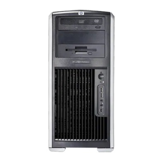
Front panel components The following image shows a typical HP xw9400 Workstation. Drive configurations can vary. Figure 1-2 Front panel components Table 1-2 Front panel components Item Symb Description Item Symb Description Optical drive Headphone connector 5.25-inch drive bay USB 2.0 ports Diskette drive (optional) Hard drive activity light IEEE-1394a connector... -
Page 14: Rear Panel Components
Rear panel components Figure 1-3 Rear panel components Table 1-3 Rear panel components Item Symbol Description Item Symb Description Power cord connector Graphics adapter Built In Self Test (BIST) LED Audio line-in connector Serial connector RJ-45 network connectors SPDIF OUT** IEEE-1394a connector Keyboard connector Mouse connector... -
Page 15: Product Specifications
the side panel of the unit and on the rear panel. Keep the serial number available when contacting customer service for assistance. Figure 1-4 Serial number and COA label location Product specifications The following table lists the physical dimensions. Table 1-4 Physical characteristics Weight (depending on 18-27.7 kg (39.6-61.1 lb.) -
Page 16: Power Supply And Cooling
Power supply and cooling This section describes power supply specifications. Table 1-5 Power supply source voltages Source voltage Description +3.3V PCI, PCIe, onboard logic, SAS controller, IEEE 1394, and chipset Storage (disk, optical, diskette), PCI, audio, USB, input to onboard regulator, and onboard logic +12 V-CPU0 Input to onboard regulator that supplies power to CPU0 and CPU0 fan... - Page 17 CAUTION: Do not exceed 150 watts of 3.3V and 5V power combination. Do not exceed 84.0 amps (1008W) of 12V (CPU0/CPU1/M/B/D/G1/G2/R) power combination. Do not exceed 1050 watts of total continuous output power. ENWW Product specifications...
-
Page 18: Power Supply Specifications
Power supply specifications The integrated, surge-tolerant power supply is rated to withstand a power surge of up to 2,000 V (line- to-PE or neutral-to-PE) and 1,000 V (line-to-line) without any data loss or system downtime. The following specifications describe the power supply: Table 1-7 Power supply specifications Item... -
Page 19: System Fans And Airflow
System fans and airflow The workstation includes one rear system fan, one memory fan, one processor (CPU) heatsink fan for each processor, and one power supply fan, plus a front system fan. Resetting the power supply If an overload triggers the power supply overload protection, all power is immediately shut off. To reset the power supply unit: Disconnect the power cord. -
Page 20: Environmental Specifications
Environmental specifications This section describes environmental specifications of your workstation. Operating: 5 to 35°C (40 to 95°F) Non-operating: -40 to 60°C (-40 to 140°F) Temperature NOTE: Derate by one degree C (1.4 degrees F) for every 305m (1,000 ft.) altitude over 1,524m (5,000 ft.). Operating: 8 to 85% RH, non-condensing Humidity Non-operating: 8 to 90% RH, non-condensing... -
Page 21: Chipkill Support
NOTE: If a graphics card requiring more than 75W is installed in Slot 2, HP recommends not using slot 3, which is the PCI slot below the graphics slot. If a graphics card requiring more than 75W is installed in slot 5, HP recommends not using slot 6, which is the PCI-X 100 slot below the graphics slot. In addition to these slot power specifications, the overall power consumption of the system (including I/O cards, processors, memory, and drives) must not exceed the maximum ratings of the system power supply. -
Page 22: Multi-Core Processors
To take advantage of this energy savings: ● The Power Management feature has been preset to suspend the workstation to a sleep state after 30 minutes of inactivity. ● The Power Management feature has been preset to suspend the monitor to a sleep state after 15 minutes of inactivity. -
Page 23: Setting Up The Operating System
Setting up the operating system This chapter provides setup and update information for the workstation operating system. It includes these topics: Topics Setting up the Microsoft operating system on page 14 Setting up Red Hat Enterprise Linux on page 15 Setting up Novell SLED on page 16 Updating the workstation on page 16 This chapter also includes information on how to determine that you have the latest BIOS, drivers, and... -
Page 24: Setting Up The Microsoft Operating System
Setting up the Microsoft operating system NOTE: If you ordered a downgrade from Windows Vista to Windows XP Professional operating system, your system will be preinstalled with Windows XP Professional operating system. With this configuration, you will receive recovery media for Windows Vista operating system only. In case you need to restore or recover the Windows XP Professional operating system in the future, it is important that you create recovery media disks for Windows XP Professional operating system after first boot. -
Page 25: Setting Up Red Hat Enterprise Linux
Setting up Red Hat Enterprise Linux HP offers an HP Installer Kit for Linux (HPIKL) to supplement Red Hat box sets and help HP Linux customers customize their system image. The HPIKL contains the HP driver CD and device drivers to successfully setup up the Red Hat Enterprise Linux (RHEL) operating system, The HP Installer Kit for Linux CDs are currently available for download at http://www.hp.com/support/workstation_swdrivers. -
Page 26: Installing And Customizing Red Hat-Enabled Workstations
Installing and customizing Red Hat-enabled workstations Linux-enabled workstations require the HP Installer Kit and the purchase of a Red Hat Enterprise Linux box set. The Installer kit includes the HP CDs necessary to complete the installation of all versions of the Red Hat Enterprise Linux box set that have been qualified to work on an HP workstation. -
Page 27: Determining Current Bios
Determining current BIOS To determine the current BIOS of the workstation during system power up: Wait for F10=setup to appear on the lower right corner of the screen. Press to enter the F10 Setup utility. The F10 Setup utility displays the workstation BIOS version under File > System Information. Note the workstation BIOS version so that you can compare it with the BIOS versions that appear on the HP website. -
Page 28: Upgrading Bios
Upgrading BIOS To find and download the latest available BIOS, which includes the latest enhancements: Go to http://www.hp.com/go/workstationsupport. Select Download Drivers and Software from the left menu column under Tasks. Follow the instructions to locate the latest BIOS available for the workstation. If the BIOS on the Web site is the same as the version on your system, no further action is required. -
Page 29: Restoring The Operating System
Restoring the operating system This chapter describes how to restore the Windows or Linux operating system. It includes these topics: Topics Restore methods on page 19 Ordering backup software on page 20 Restoring Windows Vista on page 20 Restoring Windows XP Professional on page 21 Restoring Novell SLED on page 23 Installing with the HP driver CD on page 15 Restore methods... -
Page 30: Ordering Backup Software
Ordering backup software If you cannot create system recovery CDs or DVDs, you can order a recovery disk set from the HP support center. To obtain the support center telephone number for your region visit http://www.hp.com/ support/contactHP. Restoring Windows Vista This section describes how to restore Windows Vista. -
Page 31: Restoring Windows Xp Professional
Restoring Windows XP Professional This section describes how to restore the Windows XP Professional operating system. NOTE: The workstation must have a CD or DVD writer installed to create the media set. Creating RestorePlus! media The RestorePlus! kit can be created using the files contained on the hard drive. To create the restore media: Boot the workstation. -
Page 32: Creating Hp Backup And Recovery (Hpbr) Media
Creating HP Backup and Recovery (HPBR) media NOTE: HPBR functionality is used with Windows XP only. For details, refer to the SoftThinks guide on the Documentation and Diagnostics CD included with the workstation. The Initial Recovery Point can be burned to optical media and used to recover a system. This section describes making the media. -
Page 33: Restoring The Operating System
Restoring the operating system CAUTION: Before you restore the operating system, back up your data. When you run RestorePlus! from media, the process deletes all information on the primary hard drive, including all partitions. If you run RestorePlus! from the recovery partition, only the root (C:) partition is affected. - Page 34 NOTE: Make copies of the ISO recovery images on CD as backup files in case your workstation experiences a hard drive failure. Chapter 3 Restoring the operating system ENWW...
-
Page 35: System Management
System management This section describes the various tools and utilities that allow for the system management of the workstation. ● Computer Setup (F10) Utility on page 25 ● Desktop management on page 36 Computer Setup (F10) Utility The Computer Setup Utility enables you to: ●... -
Page 36: Bios Rom
● Secure the integrated I/O functionality, including the serial and USB ports, audio, embedded NIC, SAS, or IEEE 1394 so that the I/O functionality cannot be used until they are unsecured. ● Enable or disable removable media boot ability. ● Enable or disable removable media write ability (when supported by hardware). -
Page 37: Using Computer Setup (F10) Utility
Using Computer Setup (F10) Utility You can call up the Computer Setup Utility during workstation restart or power on. To access the Computer Setup Utility menu: Power on or restart the workstation. Press the key as soon as your display is active and the message Setup appears in the lower right corner of the screen. -
Page 38: Computer Setup (F10) Utility Menu
Computer Setup (F10) Utility menu NOTE: The following content is subject to change with new BIOS releases, so your menu may be different than shown in Table 1–1. Table 4-1 Computer Setup Utility menu descriptions Heading Option Description File System Lists product name, SKU number, processor type/speed/stepping, cache size Information (L1/L2), memory type and size, integrated Media Access Control (MAC) IDs for... - Page 39 Table 4-1 Computer Setup Utility menu descriptions (continued) Heading Option Description Hard Disk Identifies the hard disk drives on the system by model, firmware, serial number, connector color, emulation type, multisector transfers, and translation mode. By default, SATA drives are not listed here. Default values can be set here for IDE and SATA drives, but not for SAS drives.
- Page 40 Table 4-1 Computer Setup Utility menu descriptions (continued) Heading Option Description SATA Controller #2 Enables/disables SATA controller 2. IDE Controller Enables/disables IDE controller. Boot Order Enables you to configure the boot, diskette drive, and hard drive orders by physically reordering the menu entries. Each device on the list can be individually excluded from or included for consideration as a bootable operating system source.
- Page 41 Table 4-1 Computer Setup Utility menu descriptions (continued) Heading Option Description Device Makes the following devices available or hidden to the system: Security ● Serial Port ● All USB Ports ● External USB ports ● Front USB Ports ● System Audio ●...
- Page 42 Table 4-1 Computer Setup Utility menu descriptions (continued) Heading Option Description OS Security Data Execution Prevention Enables/disables Data Execution Prevention mode in the processors. This mode prohibits code from running in pages that were set up as data pages, and prevents attacks such as buffer overflows.
- Page 43 Table 4-1 Computer Setup Utility menu descriptions (continued) Heading Option Description POST Messages (Enable/Disable). When enabled, POST displays non-error messages to the screen. F9 Prompt (Displayed/Hidden) Displays F9=Boot Menu during POST. Hiding this feature prevents the text from being displayed, but pressing still calls up the boot menu.
- Page 44 Table 4-1 Computer Setup Utility menu descriptions (continued) Heading Option Description ACPI S3 Hard Disk Reset (Enable/Disable) When awakening from the ACPI S3 state, reset IDE hard drive before returning to the OS. ACPI S3 PS2 Mouse Wake Up (Enable/Disable) Allow the mouse to awaken the system from the ACPI S3 state.
- Page 45 Table 4-1 Computer Setup Utility menu descriptions (continued) Heading Option Description I/O** APIC APIC Interrupts Allow manual configuration of system IRQs. For more details on using this feature and on maximizing interrupt performance, refer to the Optimizing APIC Interrupt Assignments on the xw9400 white paper available at http://tclperf.fc.hp.com/performance_briefs/index.htm.
-
Page 46: Desktop Management
Table 4-1 Computer Setup Utility menu descriptions (continued) Heading Option Description Slot Options Modifies options for: ● Slot 1—PCI Express x8 ● Slot 2—PCI Express x16 graphics ● Slot 3—PCI 32 bit, 33 MHz ● Slot 4—PCI Express x16 (x8) ●... -
Page 47: Remote System Installation
The best deployment method depends on your information technology environment and processes. The PC Deployment section of the HP Lifecycle Solutions website (http://whp-sp-orig.extweb.hp.com/ country/us/en/solutions.html) provides information to help you select the best deployment method. The Restore Plus! CD, ROM-based setup, and ACPI hardware provide further assistance with recovery of system software, configuration management and troubleshooting, and power management. -
Page 48: Altiris Client Management Solutions
Altiris Client Management solutions HP and Altiris have partnered to provide comprehensive, tightly integrated systems management solutions to reduce the cost of owning HP client PCs. HP Client Manager Software is the foundation for additional Altiris Client Management Solutions that address: ●... -
Page 49: Proactive Change Notification
Proactive Change Notification The Proactive Change Notification program uses the Subscriber's Choice website to proactively and automatically send you: ● Proactive Change Notification (PCN) emails informing you of hardware and software changes to most commercial workstations and servers, up to 60 days in advance. ●... -
Page 50: Failsafe Boot Block Rom
FailSafe Boot Block ROM The FailSafe Boot Block ROM allows for system recovery in the unlikely event of a ROM flash failure, for example, if a power failure occurs during a ROM upgrade. The Boot Block is a protected section of the ROM that checks for a valid system ROM flash when the system is powered on. -
Page 51: Replicating The Setup
Table 4-2 PS2 keyboard light combinations used by Boot Block ROM (continued) Light State Description FailSafe Keyboard LED State/Message Boot Block Activity Mode Num, Caps, Boot Block ROM Flash successful. Scroll Lock Diagnostic lights do not flash on USB keyboards. Replicating the setup The following procedures enable you to easily copy one setup configuration to other workstations of the same model to provide faster, more consistent configuration of multiple workstations. -
Page 52: Dual-State Power Button
This method takes a little longer to prepare the configuration diskette or USB, but copying the configuration to target workstations is significantly faster. NOTE: A bootable diskette or USB is required for this procedure. If Windows XP is not available to create a bootable diskette or USB, use the method for copying to a single workstation instead (see Copying to a single workstation on page 41). -
Page 53: Worldwide Web Site
Worldwide web site HP engineers rigorously test and debug software developed by HP and third-party suppliers, and develop operating system specific support software, to ensure performance, compatibility, and reliability for HP workstations. When making the transition to new or revised operating systems, it is important to implement the support software designed for that operating system. -
Page 54: Password Security
The following table and sections refer to managing security features of the workstation locally through the Computer Setup Utility. Table 4-3 Security features overview Feature Purpose How It Is Established Removable Media Boot Prevents booting from the Computer Setup Utility Menu. Control removable media drives. -
Page 55: Establishing A Setup Password In The Computer Setup (F10) Utility
A network-wide setup password can be established to enable the system administrator to log in to all network systems to perform maintenance without having to know the power-on password. NOTE: System Software Manager and HP Client Manager Software allow remote management of setup passwords and other BIOS settings in a networked environment. -
Page 56: Entering A Power-On Password
Entering a power-on password To enter a power-on password: Power on or restart the workstation. When the key icon appears on the monitor, enter the current password, and press Enter. NOTE: Type carefully. For security reasons, the characters you enter do not appear on the screen. If you enter the password incorrectly, a broken key icon appears. -
Page 57: Deleting A Power-On Or Setup Password
NOTE: See the table of National keyboard delimiter characters on page 47 for information about the alternate delimiter characters. The power-on password and setup password can also be changed using the Security menu in the Computer Setup Utility. Deleting a power-on or setup password To delete a power-on or setup password: Power on or restart the workstation. -
Page 58: Hood Sensor (Smart Cover Sensor)
Hood sensor (Smart Cover Sensor) The optional hood sensor is a combination of hardware and software technology that can alert you when the workstation side access panel has been removed. There are three levels of protection, as described in the following table. Table 4-5 Hood sensor protection levels Level... -
Page 59: Access Panel Key Lock
Access panel key lock This lock prevents removal of the access panel and all internal components. The key is shipped on the rear of the workstation. Fault notification and recovery Fault notification and recovery features combine innovative hardware and software technology to prevent the loss of critical data and minimize unplanned downtime. -
Page 60: Removal And Replacement Procedures
Removal and replacement procedures This chapter describes removal and replacement procedures of most internal components. ● Warnings and cautions on page 50 ● Service considerations on page 51 ● Customer Self Repair on page 55 ● Pre-disassembly procedures on page 55 ●... -
Page 61: Service Considerations
CAUTION: Observe the following cautions when removing or replacing a processor: — Installing a processor incorrectly can damage the system board. Contact an HP authorized reseller or service provider to install the processor. If you plan to install the processor yourself, read all of the instructions carefully before you begin. -
Page 62: Generating Static
Generating static The following table shows that different activities generate different amounts of static electricity. Static electricity increases as humidity decreases. Table 5-1 Static electricity Relative Humidity Event Walking across carpet 7,500 V 15,000 V 35,000 V Walking across vinyl floor 3,000 V 5,000 V 12,000 V... -
Page 63: Personal Grounding Methods And Equipment
Personal grounding methods and equipment Use the following equipment to prevent static electricity damage to equipment: ● Wrist straps are flexible straps with a maximum of one megohm ± 10% resistance in the ground cords. To provide a proper ground, wear the strap against bare skin. The ground cord must be connected and fit snugly into the banana plug connector on the grounding mat or workstation. -
Page 64: Required Tools And Software
● Wrist straps and footwear straps providing one-megohm ± 10% resistance ● Material handling packages ● Conductive plastic bags and tubes ● Conductive tote boxes ● Opaque and transparent metallized shielded bags ● Transparent shielding tubes Required tools and software The following tools and software are required to service your workstation: ●... -
Page 65: Lithium Coin Cell Battery
● Do not use excessive force when inserting a drive. ● Avoid exposing a hard drive to liquids, temperature extremes, or products that have magnetic fields such as monitors or speakers. Lithium coin cell battery The battery that comes with the workstation provides power to the real-time clock and has a minimum lifetime of about three years. -
Page 66: System Board Components
System board components The following image shows the system board connectors and sockets on the HP xw9400 Workstation. Figure 5-1 System board identification Table 5-3 System board components Description Item Description Item Description Item Description Main power Memory fan Front control Primary IDE** panel Memory module... -
Page 67: System Board Architecture
Table 5-3 System board components (continued) Description Item Description Item Description Item Description LAN/USB CD audio Hard disk activity CPU0 Chassis fan Auxiliary audio Password CPU1 fan jumper LAN/USB Front audio Crisis recovery Memory power jumper Audio Front IEEE 1394 PCI fan * The PCI Express x16 is a PCI Express x16 connector that has x8 bandwidth. -
Page 68: Removing And Replacing Components
Removing and replacing components This section discusses the procedures necessary to remove and install various hardware components on your workstation. Before servicing or upgrading your workstation: Review the safety precautions and the Service considerations on page 51, as well as the Safety and Regulatory Information. -
Page 69: Disassembly Order
Disassembly order Use the following table to determine the sequence in which to remove the major components. Pre-disassembly (Pre- disassembly procedures on page Locks (Security lock (optional) on page Access panel (Access panel on page Hood sensor (Hood sensor (Smart cover sensor) on page Front bezel (Front... - Page 70 Hard drive (Hard drive on page CPU heatsink (Removing the CPU heatsink on page 113) Processor (Removing the processor on page 117) PCI retainer (PCI retainer on page PCI retention clamp (PCI retention clamp on page PCI or PCI Express card (Removing PCI or PCI Express cards on page CPU heatsink...
-
Page 71: Security Lock (Optional)
Security lock (optional) If a security padlock is installed, remove it before servicing the unit. To remove the padlock, unlock it and slide it out of the padlock loop as shown in the following image. Figure 5-3 Removing the security lock Cable lock (optional) If a cable lock is installed, remove it before servicing the unit. -
Page 72: Universal Chassis Clamp Lock (Optional)
Universal chassis clamp lock (optional) If a universal chassis clamp lock is installed, remove it before servicing the unit. To remove the lock: Unlock the device and remove the locking mechanism. Remove the screw attaching the lock to the chassis. Chapter 5 Removal and replacement procedures ENWW... -
Page 73: Access Panel
Access panel Before accessing the internal components of the workstation, the access panel must be removed. To remove the access panel: WARNING! Before removing the workstation access panel, be sure that the workstation is powered off and that the power cord is disconnected from the electrical outlet. Disconnect power from the system. -
Page 74: Front Bezel
Front bezel To remove the front bezel: Lift up on the three (1) tabs located on the front bezel. Rotate the front bezel away (2) from the chassis, and remove the bezel. Figure 5-6 Opening the front bezel Bezel blanks To remove the bezel blanks: Disconnect power from the system, (Pre-disassembly procedures on page... -
Page 75: Hood Sensor (Smart Cover Sensor)
Hood sensor (Smart cover sensor) To remove the hood sensor: Disconnect power from the system (Pre-disassembly procedures on page 55) and remove the access panel (Access panel on page 63). Remove the front bezel. Lay the workstation on its side with the system board facing up. -
Page 76: Front Panel I/O Device Assembly
Front panel I/O device assembly To remove the front panel I/O device assembly: Disconnect power from the system (Pre-disassembly procedures on page 55). Remove the access panel (Access panel on page 63) and the front bezel (Front bezel on page 64). -
Page 77: Power Button Assembly And System Speaker
Power button assembly and system speaker The power button and the system speaker are part of the same assembly. To remove the power button: Disconnect power from the system (Pre-disassembly procedures on page 55) and remove the access panel (Access panel on page 63). - Page 78 Slide the speaker away from the three flanges and remove it from the chassis. Figure 5-11 Removing the speaker Chapter 5 Removal and replacement procedures ENWW...
-
Page 79: Power Supply
Power supply Disconnect power from the system (Pre-disassembly procedures on page 55), and remove the access panel (Access panel on page 63). Place the workstation on its side with the system board facing up. Disconnect the three power supply cable connectors from the system board. NOTE: Cable ties and cable clips may be present. -
Page 80: System Fan
System fan To remove the system fan: Disconnect power from the system (Pre-disassembly procedures on page 55), and remove the access panel (Access panel on page 63). Place the workstation on its side with the system board facing up. Disconnect the fan power plug from the system board (1). Press down on the ribbed portion of the system fan housing (2), rotate the fan housing down, and lift the unit out of the chassis. -
Page 81: Memory Fan
Memory fan To remove the memory fan: Disconnect power from the system (Pre-disassembly procedures on page 55), and remove the access panel (Access panel on page 63). Place the workstation on its side with the system board facing up. Disconnect the memory fan power plug from the system board (1). NOTE: If the fan is simply being moved to access the DIMMs, it does not need to be disconnected from the system board. -
Page 82: Memory
Memory Memory module features ● Eight memory slots for DIMMs, four per CPU ● Accepts 512-MB, 1-GB , 2-GB, 4-GB, and 8-GB DIMMs ● 64-GB maximum configuration with 8-GB DIMMs ● Standard ECC PC2-5300 DIMMs ● No support for mirroring ●... -
Page 83: Removing Memory Module
Removing memory module Disconnect power from the system (Pre-disassembly procedures on page 55), and remove the access panel (Access panel on page 63). Place the workstation on its side with the system board facing up. CAUTION: To ensure that memory modules are not damaged during removal or installation, power off the workstation and unplug the power cord from the AC power outlet. - Page 84 Lift the DIMM straight up, and remove it from the unit (2). Figure 5-16 Removing DIMM NOTE: DIMMs and DIMM sockets are keyed for proper installation. Be sure these guides align when installing a DIMM. Chapter 5 Removal and replacement procedures ENWW...
-
Page 85: Installing A Memory Module
Installing a memory module NOTE: HP only ships DIMMs that are electrically and thermally compatible with this product. Because third-party DIMMs might not be electrically or thermally compatible, they are not supported by HP. Disconnect power from the system (Pre-disassembly procedures on page 55) and remove the access panel (Access panel on page... - Page 86 NOTE: DIMMs and DIMM sockets are keyed for proper installation. Be sure these guides align when installing a DIMM. Lower the memory fan until it snaps into place. NOTE: Ensure that all cables are clear of the fan housing when lowering the memory fan. The BIOS generates warnings/errors on invalid memory configurations.
-
Page 87: Pci Slots
PCI slots Figure 5-19 Identifying PCI slots Table 5-4 PCI slots Slot Type PCI Express x16 (x8) PCI Express x16 graphics PCI 32 bit, 33 MHz PCI Express x16 (x8) PCI Express x16 graphics PCI-X 100 PCI-X 100/133 ENWW Removing and replacing components... -
Page 88: Pci Retainer
PCI retainer For added protection, some cards have PCI retainers installed to prevent movement during shipping. Removing the PCI retainer Disconnect power from the system (Pre-disassembly procedures on page 55), and remove the access panel (Access panel on page 63). Place the workstation on its side with the system board facing up. - Page 89 For both short and tall PCI cards, attach the hooks of the PCI retainer (1) under the slots on the rear of the chassis, and then rotate the retainer down until the retainer arm (2) supports the card. Figure 5-21 Installing the short or tall card PCI retainer ENWW Removing and replacing components...
-
Page 90: Pci Retention Clamp
PCI retention clamp Disconnect power from the system (Pre-disassembly procedures on page 55), and remove the access panel (Access panel on page 63). Place the workstation on its side with the system board facing up. Open the PCI retention clamp by pressing down on the two green clips at the ends of the clamp and rotating the clamp toward the back of the system. -
Page 91: Pci Express
PCI Express PCI Express is a point-to-point architecture and uses a serial data transmission protocol. A single PCI Express lane consists of four wires and can transmit 250 MB/s in a single direction or 500 MB/s in both directions simultaneously. This bandwidth is not affected by what is happening on other PCI Express buses or legacy PCI/PCI-X buses (provided that total bandwidth can be handled by the CPU and the memory subsystem.) The transmission protocol is somewhat similar to that used for a LAN connection and contains error correction and detection, packet addressing, and other network features. -
Page 92: Removing Pci Or Pci Express Cards
Removing PCI or PCI Express cards Disconnect power from the system (Pre-disassembly procedures on page 55), and remove the access panel (Access panel on page 63). Place the workstation on its side with the system board facing up. Remove the PCI retainer (PCI retainer on page 78) if present. -
Page 93: Pci Or Pci Express Installation
PCI or PCI Express installation Disconnect power from the system (Pre-disassembly procedures on page 55), and remove the access panel (Access panel on page 63). Place the workstation on its side with the system board facing up, and remove the PCI retainer (PCI retention clamp on page 80). -
Page 94: Front Fan Removal
Front fan removal To remove the front fan: Disconnect power from the system (Pre-disassembly procedures on page 55), and remove the access panel (Access panel on page 63). Place the workstation on its side with the system board facing up. Disconnect optical and floppy drive cables from the system board. - Page 95 To install the front fan: Place the fan in the card guide with the fan label facing into the card guide, and the fan protector screen facing outward. NOTE: Ensure that the fan blows toward the rear of the chassis. Thread the front fan cable through the slot in the card guide.
-
Page 96: Front Fan Jumper Cable Installation
Front fan jumper cable installation This procedure describes how to install a front fan jumper cable in an HP xw9400 Workstation when a 4 GB or greater DIMM is used in the workstation. The additional jumper cable provides for quieter fan operation. - Page 97 Place the excess cable in the empty space under the hard drive cage. Figure 5-31 Place excess cable in chassis Connect the system fan jumper cable to the front fan cable connector on the system board. Use the system board connector to which the original front fan cable connected. Figure 5-32 Connect system fan jumper cable to system board ENWW...
-
Page 98: Battery
Battery CAUTION: Before removing the battery, be sure your CMOS settings are backed up because all CMOS settings are lost when the battery is removed. To back up the CMOS settings, use Computer Setup and run the Save to Diskette option from the File menu. To remove the battery: Disconnect power from the system (Pre-disassembly procedures on page... -
Page 99: Power Connections To Drives
Power connections to drives For help in identifying power cables, refer to the following figure and table. Route or tie cables so that they cannot interfere with the CPU heatsink fans. Figure 5-34 Identifying correct power connections Table 5-6 Power connector descriptions Connector Description 24-pin main power... -
Page 100: Optical Drive
Optical drive Your workstation might have a SATA or an IDE optical drive. To remove the optical drive: Disconnect power from the system (Pre-disassembly procedures on page 55) and remove the access panel (Access panel on page 63). Disconnect the audio (1), data (2), and power (3) cables from the drive. The connector colors might be different than illustrated. - Page 101 To replace an optical drive: Lift the green drivelock release lever while sliding the optical drive into the bay. When the optical drive is partially inserted, release the drivelock release lever, and slide the drive completely into the bay until the drive is secured. CAUTION: Ensure that the optical drive is secure.
-
Page 102: Replacing The Sata Optical Drive Data Cable
Replacing the SATA optical drive data cable If your workstation has a SATA optical drive, replace the cable as follows: Disconnect power from the system (Pre-disassembly procedures on page 55), and remove the access panel (Access panel on page 63). Place the workstation on its side with the system board facing up. -
Page 103: Diskette Drive (Optional)
Diskette drive (optional) To remove a diskette drive: Disconnect power from the system (Pre-disassembly procedures on page 55). Remove the access panel (Access panel on page 63) and the front bezel (Front bezel on page 64). Disconnect the data and power cables from the back of the diskette drive. Figure 5-38 Disconnecting cables from the diskette drive While lifting the green drivelock release tab, slide the drive forward out of the chassis. - Page 104 Remove the diskette drive from its bracket by removing the two M3 screws in the rear-most holes and pulling the diskette drive from the bracket. Figure 5-40 Removing the diskette drive from the bracket To replace a diskette drive: Slide the diskette drive into the bracket, and secure it with two M3 screws. While lifting the green drivelock release tab, slide the drive into the chassis.
-
Page 105: Hard Drive
Hard drive Replacing a hard drive For more information on SATA hard drives and the SATA RAID configuration, see Appendix B—SATA devices on page 172. Removing a hard drive Disconnect power from the system (Pre-disassembly procedures on page 55), and remove the access panel (Access panel on page 63). -
Page 106: Installing A Hard Drive
Installing a hard drive Select a drive bay in which to install the drive. If installing more than one hard drive, use the hard drive order shown in the following image. Figure 5-43 Identifying hard drive installation order Squeeze the green tabs, and slide the rails out of the empty bay. Attach the rails to the hard drive. - Page 107 Attach a data cable from a SATA connector on the system board to the hard drive, and attach a power cable to the drive. Figure 5-45 Replacing the SATA hard drive For a SAS hard drive, attach a SAS/SATA adapter to the connector on the hard drive. Attach a data cable from a SAS connector on the system board to the hard drive, and attach a power cable to the drive.
-
Page 108: Installing A Hard Drive In The Fifth Hard Drive Bay
Installing a hard drive in the fifth hard drive bay To install a SAS or SATA hard drive into fifth HDD bay: Place the workstation on its side, and remove the three drive screws that are located on the bottom of the chassis. -
Page 109: Liquid Cooling Unit
Liquid cooling unit The following section describes how to remove a processor liquid cooling unit. Removing the liquid cooling unit The following steps describe removal of a liquid cooling unit. Disconnect power from the system (Pre-disassembly procedures on page 55), and remove the access panel (Access panel on page 63). - Page 110 Raise the radiator to its upright position. Figure 5-50 Raise the radiator Disconnect the memory fan (1), radiator fan (2), and voltage regulator fan (3) cables from the system board. Pull the memory fan cable clear of the liquid cooling unit. Figure 5-51 Disconnect memory, radiator, and voltage regulator fan cables 100 Chapter 5 Removal and replacement procedures...
- Page 111 Alternately and evenly loosen the two liquid cooling unit/CPU 1 mounting screws from the liquid cooling unit. Figure 5-52 Loosen liquid cooling unit/CPU 1 mounting screws Lower the fan/radiator to its closed position. For convenience, disconnect the PSU (1) cable from the system board. Disconnect the liquid cooling unit pump cable (2) from the system board.
- Page 112 Press the green tab in on the memory fan housing (1) and lift the unit from the system board (2). Carefully pull the memory fan cable from the liquid cooling unit. Figure 5-54 Removing the memory fan Raise the liquid cooling unit fan/radiator to its upright position and remove the unit from the workstation.
-
Page 113: Installing A Liquid Cooling Unit
Installing a liquid cooling unit The following steps describe installation of a liquid cooling unit. Disconnect power from the system (Pre-disassembly procedures on page 55), and remove the access panel (Access panel on page 63). Place the workstation on its side with the system board facing up. - Page 114 NOTE: Do not remove the interface material from a new liquid cooling unit. Ensure all cables are clear of the installation area in the chassis. For convenience, disconnect P15 and/or P16 power cables from the graphics cards (if applicable), and disconnect the P3 power connector from the system board.
- Page 115 Lower the liquid cooling unit fan/radiator. Install the workstation memory fan. Lower the memory fan assembly into the workstation chassis and snap it into place. Figure 5-60 Removing the memory fan Guide the memory fan cable through the liquid cooling unit radiator tubing as shown in the following illustration.
- Page 116 Connect the memory fan cable to the system board. Figure 5-62 Connect memory fan cable Connect the cables for the radiator fan (1) and voltage regulator fan (2) to the system board. For convenience, you may remove any nearby PC card from its slot while you connect cables. CAUTION: Ensure that no cables interfere with the liquid cooling unit's system board mounts or with other components on the system board.
- Page 117 Alternately and evenly tighten the liquid cooling unit/CPU 1 mounting screws to a torque of 6 in./ lbs. Figure 5-64 Tighten liquid cooling unit/CPU 1 mounting screws Lower the radiator to its closing position. Alternately and evenly tighten the liquid cooling unit/CPU 0 mounting screws to a torque of 6 in./ lbs.
- Page 118 Tighten the radiator mounting screws. Figure 5-66 Position radiator and tighten mounting screws Connect the liquid cooling unit pump cable to the system board. Figure 5-67 Connect pump cable to system board 108 Chapter 5 Removal and replacement procedures ENWW...
- Page 119 If appropriate, reconnect power cable P3 to the system board. Figure 5-68 Reconnect P3 to system board If appropriate, reconnect power cables P15 and/or P16 to the graphics cards. ENWW Removing and replacing components 109...
-
Page 120: Replacing The Liquid Cooling Unit Vrd Fan
Replacing the liquid cooling unit VRD fan This section explains how to replace the VRD fan in the liquid cooling unit. Removing the VRD fan To remove the VRD fan: Remove the VRD cable from the cable channel. Remove the VRD fan from its holder. Grasp the fan and pull up. 110 Chapter 5 Removal and replacement procedures ENWW... -
Page 121: Installing The Vrd Fan
Installing the VRD fan To install the VRD fan: Position the VRD fan such that the indicator arrow on the fan points in the same direction as the indicator arrow in the fan holder. Insert the fan in its holder. Press down until the fan snaps into place. - Page 122 Position the VRD cable in the cable channel. 112 Chapter 5 Removal and replacement procedures ENWW...
-
Page 123: Processor Heatsink
Processor heatsink Removing the CPU heatsink NOTE: The following illustrated CPU heatsink is typical of what you might have in your workstation. Be aware that different variations of the CPU heatsinks exist, but the overall procedures listed are sufficient to assist you in removing the CPU heatsink. Shut down the workstation, and disconnect power from the system (Pre-disassembly procedures on page... - Page 124 Before lifting the heatsink, carefully break the thermal compound between the CPU heatsink and processor by moving the heatsink back and forth or twisting it (3). Figure 5-70 Removing the CPU heatsink from the system board Use alcohol and a soft cloth to clean all of the thermal interface material residue from the CPU heatsink and processor.
-
Page 125: Replacing The Cpu Heatsink
Replacing the CPU heatsink Disconnect power from the system (Pre-disassembly procedures on page 55). Remove the access panel (Access panel on page 63) and the CPU heatsink (Removing the CPU heatsink on page 113). Use alcohol and a soft cloth to clean all of the thermal grease from the CPU heatsink and processor. CAUTION: Allow the alcohol on the processor and CPU heatsink to dry completely. - Page 126 Connect the CPU heatsink fan connector to the system board (2). Figure 5-72 Replacing the CPU heatsink on the system board Insert and tighten the two CPU heatsink screws. First, tighten both screws partially so that the CPU heatsink remains level. Next, fully tighten one screw (1), then fully tighten the remaining screw (2).
-
Page 127: Processor
Processor Removing the processor CAUTION: Use extreme care when installing or removing a processor. The exposed socket pins are extremely fragile. Damaged sockets will require a board replacement. Lift the processor out of the socket— do not slide the processor on the socket. When installing a processor, align the dimples on the side of the processor with the notches in the socket. - Page 128 Lift the processor straight out of the socket. Figure 5-75 Lift the processor from the socket CAUTION: To avoid bending the socket pins, keep the processor perfectly flat when removing or installing it. NOTE: Store the processor in a static-free, safe place where it will not be damaged. In some workstation configurations, a bypass board may be installed in the socket instead of a processor.
-
Page 129: Replacing The Processor
Replacing the processor CAUTION: HP recommends you do not swap processors (CPUs) from one motherboard to another. CAUTION: Use extreme care when installing or removing a processor. The exposed socket pins are extremely fragile. Damaged sockets will require a board replacement. Lift the processor out of the socket—... -
Page 130: System Board
System board Removing the system board Disconnect power from the system (Pre-disassembly procedures on page 55), and remove the access panel (Access panel on page 63). Place the workstation on its side with the system board facing up. Remove all expansion boards, external cables, graphics cards (Removing PCI or PCI Express cards on page 82), and the CPU heatsink... -
Page 131: Product Recycling
Install the heatsink (Replacing the CPU heatsink on page 115). Install all removed components and cables. Product recycling HP encourages customers to recycle used electronic hardware, HP original print cartridges, and rechargeable batteries. For information about recycling HP components or products, see http://www.hp.com/go/recycle. ENWW Product recycling 121... -
Page 132: System Diagnostics And Troubleshooting
System diagnostics and troubleshooting This chapter discusses the tools available for diagnosing and troubleshooting system issues. ● HP troubleshooting resources and tools on page 122 ● Troubleshooting checklist on page 125 ● LED color definitions on page 125 ● Self-troubleshooting with HP Vision Field Diagnostics on page 126 ●... -
Page 133: Troubleshooting A Problem
● http://www.hp.com/support—Provides a listing of the worldwide technical support phone numbers. Access the telephone numbers by visiting the Web site, then select your region, and click Contact HP in the upper-left corner. ● http://www.hp.com/support/workstation_swdrivers—Provides access to software and drivers for workstations. -
Page 134: Helpful Hints
Helpful hints If you encounter a problem with the workstation, monitor, or software, the following provides a list of general suggestions that help you isolate and focus on the problem before taking further action. At startup ● Verify that the workstation and monitor are plugged into a working electrical outlet. ●... -
Page 135: Customizing The Monitor Display
● Upgrade the BIOS. A new release of the BIOS might have been released that supports new features or fixes your problem. ● For more detailed information, see the troubleshooting chapter in the Service and Technical Reference Guide at http://www.hp.com/support/workstation_manuals. Customizing the monitor display You can manually select or change the monitor model, refresh rates, screen resolution, color settings, font sizes, and power management settings. -
Page 136: Self-Troubleshooting With Hp Vision Field Diagnostics
Self-troubleshooting with HP Vision Field Diagnostics Hewlett-Packard Vision Field Diagnostics is a diagnostic tool that can be used by the end user or technical support personnel to view information about the hardware configuration of the computer and perform hardware troubleshooting on HP Desktop and Workstation systems. This diagnostic tool should be used to help determine hardware failures. -
Page 137: Downloading And Accessing Hp Vision Field Diagnostics
The Survey tab is displayed when you invoke HP Vision Field Diagnostics. This tab shows the current configuration of the workstation. From the Survey tab, there is access to several categories of information about the workstation. Other tabs provide additional information, including diagnostic test options and test results. -
Page 138: User Interface
User interface The HP Vision Field Diagnostics application provides six major functions, accessible through Tabs. These functions are: ● Survey — Your current system hardware information. ● Test — List all diagnostics available for your system. Tests are started there. ●... - Page 139 ● Miscellaneous — List any devices or data that doesn't belong to any other Category. ● Processors - Shows system processors. ● Storage — Shows mass storage devices such as floppy drives, optical drives, SATA, SAS hard disk drives and controllers, as well as any RAID arrays. ●...
-
Page 140: Test Tab
Test tab The Test tab lists all available diagnostics. The lists have been tailored according to your system configuration. Individual test may be selected or unselected. The following Test Modes exist: ● Quick — This test selection was picked to perform quickly while covering your entire hardware. Test parameters cannot be modified. - Page 141 Click the Start Test button to start the testing. The Status tab, which allows you to monitor the progress of the tests, is automatically displayed during the testing process. When the tests are complete, the Status tab shows whether the devices passed or failed. If errors are found, go to the Errors tab to display detailed information and recommended actions.
-
Page 142: Status Tab
Status tab The Status tab shows the overall progress and status of the test scenario as well as the progress and status of each test. The color coded status are black, blue, green, red, and orange. The Status tab colors are: ●... -
Page 143: Help Tab
● The Recommended Repair will give a recommended action that should be performed to resolve the failed hardware. ● The Warranty ID is a unique error code associated with the specific error on your computer. When contacting the HP Support Center for assistance with a hardware failure, please be prepared to provide the Warranty ID. -
Page 144: Saving And Printing Information In Hp Vision Field Diagnostics
Saving and printing information in HP Vision Field Diagnostics You can save the information displayed in the HP Vision Field Diagnostics Survey, History and Errors tabs to a diskette or a USB flash drive. You can not save to the hard drive. The system will automatically create an html file that has the same appearance as the information displayed on the screen. - Page 145 Table 6-2 Diagnostic LED codes Chassis Indicator LEDs Power LED and Sound Diagnosis and Service Action Activity None CAUTION: Disconnect AC power from the workstation before reseating or replacing components because there is power to the system board even when the workstation is powered down. System does not power on.
- Page 146 Table 6-2 Diagnostic LED codes (continued) Chassis Indicator LEDs Power LED and Sound Diagnosis and Service Action Activity Blinks red/beeps four CAUTION: Disconnect AC power from the workstation before reseating or times, once per second, replacing components because there is power to the system board even then a two–second pause when the workstation is powered down.
-
Page 147: Troubleshooting Scenarios And Solutions
Table 6-2 Diagnostic LED codes (continued) Chassis Indicator LEDs Power LED and Sound Diagnosis and Service Action Activity Blinks red/beeps seven CAUTION: Disconnect AC power from the workstation before reseating or times, once per second, replacing components because there is power to the system board even then a two-second pause when the workstation is powered down. - Page 148 Table 6-3 Minor problems (continued) Problem Cause Possible Solution Workstation date and Real-time clock (RTC) Reset the date and time under Control time display is incorrect. battery might need to be Panel. replaced. Replace the RTC battery. Workstation appears to Network driver is loaded Establish a network connection, or use pause periodically.
- Page 149 Table 6-3 Minor problems (continued) Problem Cause Possible Solution Workstation powered off Processor thermal CAUTION: Disconnect AC power from the automatically and the protection activated: workstation before reseating or replacing Power LED flashes red components because there is power to the A fan might be blocked two times, once every system board even when the workstation is...
-
Page 150: Solving Power Supply Problems
Solving power supply problems Testing power supply Before reseating or replacing the power supply, use the BIST feature to determine if the power supply still works. To test the power supply: Disconnect AC power to the workstation. Disconnect all internal power supply cables. Plug in AC power. - Page 151 Table 6-4 Power supply problems (continued) Problem Cause Solution Workstation powered off Processor thermal CAUTION: Disconnect AC power from the automatically and the Power protection activated. workstation before reseating or replacing LED flashes red two times, components because there is power to the A fan might be blocked once every second, system board even when the workstation is...
-
Page 152: Solving Diskette Problems
Solving diskette problems Table 6-5 Diskette problems Problem Cause Solution Diskette drive light stays on. Diskette is damaged. Check power and data cables. Click on My Computer. Right-click on the desired hard drive and select Properties. Click the Tools tab. Click Check Now... -
Page 153: Solving Hard Drive Problems
Table 6-5 Diskette problems (continued) Problem Cause Solution Diskette drive cannot read Diskette is not formatted. Format the diskette. a diskette. You are using the wrong Be sure you use the correct diskette type for diskette type for the drive the type of drive you are using. - Page 154 Table 6-6 Hard drive problems (continued) Problem Cause Solution Drive not found (identified). Loose cable. Check cable connections. The system might not Run Computer Setup. have automatically If the system still does not recognize the recognized a newly new device, determine if the device is listed installed device.
-
Page 155: Solving Display Problems
Solving display problems Table 6-7 Display problems Problem Cause Solution Blank screen (no video). The cable connections Check the cable connections from the monitor are not correct. to the workstation and to a working electrical outlet. The monitor is off. Switch the monitor to on (LED is on). - Page 156 Table 6-7 Display problems (continued) Problem Cause Solution The display works properly The display settings in Restart the workstation and press during the POST but goes the operating system are during startup when you see Press F8 in blank when the OS starts. incompatible with your the bottom-right corner of the screen.
- Page 157 Table 6-7 Display problems (continued) Problem Cause Solution The picture is broken up, The monitor connections Be sure the monitor cable is securely rolls, jitters, or flashes. might be incomplete or connected to the workstation. the monitor might be In a two-monitor system or if another incorrectly adjusted.
-
Page 158: Solving Audio Problems
Solving audio problems Table 6-8 Audio problems Problem Cause Solution Sound does not come out of Software volume control Double-click the Speaker icon on the taskbar the speaker or headphones. is turned down. and use the volume slider to adjust the volume. The external speakers Turn on the external speakers. -
Page 159: Solving Printer Problems
Table 6-8 Audio problems (continued) Problem Cause Solution NOTE: If you set digital as the Output Mode, the internal speaker and external analog speakers will no longer output audio until you switch back to an auto-sense or analog mode. If you set analog as the Output Mode, external digital speakers will not function until you change the output mode back to an auto-sense or digital mode. -
Page 160: Solving Keyboard And Mouse Problems
Solving keyboard and mouse problems Table 6-10 Keyboard and mouse problems Problem Cause Solution Keyboard commands and Keyboard connector Power off the workstation. typing are not recognized by is not properly Reconnect the keyboard to the workstation the workstation. connected. and restart the workstation. -
Page 161: Solving Front Panel Component Problems
Solving front panel component problems If you are experiencing problems with one of the front panel ports, you might be able to try your device in the corresponding port on the back side of the computer. If this does not fix the problem, or you must use the front panel ports, continue troubleshooting. - Page 162 Table 6-12 Hardware installation problems Problem Cause Solution A new device is not Device is not seated or Be sure that the device is properly and securely recognized as part of connected properly. connected and that pins in the connector are the system.
-
Page 163: Solving Network Problems
Table 6-12 Hardware installation problems (continued) Problem Cause Solution Power LED flashes red five Memory is installed CAUTION: Disconnect AC power from the times, once every second, incorrectly or is bad. workstation before reseating or replacing followed by a two second components because there is power to the pause, and the workstation system board even when the workstation is... - Page 164 Table 6-13 Network problems (continued) Problem Cause Solution Diagnostics reports a The cable is not securely Be sure that both ends of the data cable are failure. connected. securely connected. The cable is attached to the Be sure that the cable is attached to the correct incorrect connector.
-
Page 165: Solving Memory Problems
Table 6-13 Network problems (continued) Problem Cause Solution Cannot connect to The network controller is Verify Network Connectivity, that a DHCP network server when not configured properly. Server is present, and that the Remote System attempting Remote Installation Server contains the NIC drivers for System Installation. -
Page 166: Solving Processor Problems
Table 6-14 Memory problems (continued) Problem Cause Solution Power LED flashes red 5 Memory is installed CAUTION: Disconnect AC power from the times, once every second, incorrectly or is bad. workstation before reseating or replacing followed by a 2-second components because there is power to the pause, and the workstation system board even when the workstation is beeps 5 times. -
Page 167: Solving Cd-Rom And Dvd Problems
Solving CD-ROM and DVD problems Table 6-16 CD-ROM and DVD problems Problem Cause Solution System will not boot from The CD-ROM or DVD Run the Computer Setup utility and enable CD-ROM or DVD drive. boot is not enabled booting to removable media and verify boot through the Computer order settings. -
Page 168: Solving Internet Access Problems
Solving Internet access problems Table 6-17 Internet access problems Problem Cause Solution Unable to connect to the Internet Service Verify Internet settings or contact the ISP for Internet. Provider (ISP) account is assistance. not set up properly. Modem is not set up Reconnect the modem. - Page 169 Table 6-17 Internet access problems (continued) Problem Cause Solution Cannot automatically You must log on to the Log on to the ISP and launch the desired launch Internet programs. ISP before some program. programs will start. Internet takes too long to Modem is not set up Verify that the correct modem speed and COM download websites.
-
Page 170: Post Error Messages
POST error messages POST is a program run at startup that initializes and runs some tests on installed hardware. An audible and/or visual message occurs if the POST encounters a problem. POST checks the following items to ensure that the workstation system is functioning properly: ●... - Page 171 Table 6-18 POST error messages (continued) Screen Message Probable Cause Recommended Action 163–Time and Date Invalid time or date in Set the date and time under Control Not Set configuration memory. Panel or in F10 Setup, depending on the operating system. RTC (real-time clock) battery might need to be replaced.
- Page 172 Table 6-18 POST error messages (continued) Screen Message Probable Cause Recommended Action 211–Memory warning An unknown issue with one of CAUTION: Disconnect AC power from the condition detected the DIMMs has been detected. workstation before reseating or replacing components because there is power to the system board even when the workstation is powered down.
- Page 173 Table 6-18 POST error messages (continued) Screen Message Probable Cause Recommended Action 304–Keyboard or Keyboard failure. CAUTION: Disconnect AC power from the System Unit Error workstation before reseating or replacing components because there is power to the system board even when the workstation is powered down.
- Page 174 Table 6-18 POST error messages (continued) Screen Message Probable Cause Recommended Action 517–Front IEEE 1394 Front IEEE 1394 port is not CAUTION: Disconnect AC power from the Not Connected connected. workstation before reseating or replacing components because there is power to the system board even when the workstation is powered down.
- Page 175 Table 6-18 POST error messages (continued) Screen Message Probable Cause Recommended Action 915–Fan Power from The fan power cable is not CAUTION: Disconnect AC power from the Power Supply Not connected, or the power workstation before reseating or replacing Connected supply is bad.
- Page 176 Table 6-18 POST error messages (continued) Screen Message Probable Cause Recommended Action 1155–Serial Port Both external and internal Remove any COM port expansion Address Conflict serial ports are assigned to cards. Detected. same IRQ. Clear CMOS by pressing the Clear CMOS button on the system board.
- Page 177 Table 6-18 POST error messages (continued) Screen Message Probable Cause Recommended Action 1803–CPU1 Not The system board does not CAUTION: Disconnect AC power from the Supported support the processor. workstation before reseating or replacing components because there is power to the system board even when the workstation is powered down.
-
Page 178: Appendix A Appendix A - Sas Devices
Appendix A — SAS devices Supported SAS RAID configurations The following RAID configurations are supported on the HP xw9400 Workstation. NOTE: This section does not apply to configuring RAID in the Linux environment. For RAID in the Linux environment, configure SW RAID configurations as provided by Red Hat Enterprise Linux. ●... -
Page 179: Sas Raid 1 (Im) Configuration
On the Adapter Properties screen use the arrow keys to highlight RAID Properties, then press Enter. In the Select New Array Type-SAS1068e screen, use the arrow keys to highlight Create IS Volume, then press Enter. In the Create New Array-SAS1068e screen, use the arrow keys to select the first disk for the Create IS volume. -
Page 180: Sas Raid 1E (Ime) Configuration
Use the arrow keys to select the secondary (mirrored) disk for the IM volume. Use SPACE, +, or key to select Yes as the value for the Array Disk column. When the second drive selected in RAID Disk is set to Yes, Drive Status changes to Secondary. ●... -
Page 181: Changing Boot Order
Changing boot order If the RAID array will be a data array, the disk drive with the operating system must appear higher in the boot order. If the RAID array will be the operating system drive, it should appear higher in the boot order. To change the boot order: Press to call up the BIOS Setup utility when booting the system. -
Page 182: Appendix B Appendix B-Sata Devices
Appendix B—SATA devices This appendix describes how to use the NVIDIA MediaShield utility to set up and manage SATA RAID volumes. The SATA RAID option must be enabled in BIOS and the SATA drives must be attached to the workstation ports to configure them into a RAID array. Attach the required number of SATA HDDs for the desired RAID level: ●... -
Page 183: Changing Boot Order
On the Define a New Array screen, RAID Mode is highlighted in blue and mirroring is set as the default setting. Press Enter to show the RAID modes. This mode enables control of mirroring, striping, stripe mirroring, spanning, and RAID 5. Use the up/down arrow keys to highlight in red the desired RAID type, then press Enter. -
Page 184: Deleting Raid Volumes
Deleting RAID volumes Use the NVIDIA MediaShield utility to delete RAID volumes. Press to enter the RAID setup utility when Press F6 to enter RAID setup utility is displayed. The MediaShield Utility displays the array list. One of the arrays listed is highlighted in red. Use the up/down arrow keys to highlight RAID volume to be deleted. -
Page 185: Appendix C Appendix C- Connector Pins
Appendix C— Connector pins Connector pin descriptions Ethernet connector Signal (+) Transmit Data (-) Transmit Data (+) Receive Data Unused Unused (-) Receive Data Unused Unused Serial connector Signal Carrier Detect Receive Data Transmit Data Data Terminal Ready Signal Ground Data Set Ready Request to Send Clear to Send... - Page 186 IEEE 1394 connector Signal power tpb- tpb+ tpa- tpa+ Microphone connector (1/8 inch) Signal 1 (Tip) Audio 2 (Ring) Power 3 (Shield) Ground Headphone connector (1/8 inch) Signal 1 (Tip) Audio_Left 2 (Ring) Audio_Right 3 (Shield) Ground Line-in audio connector (1/8 inch) Signal 1 (Tip) Audio_In_Left...
- Page 187 SPDIF OUT internal header Signal +VDC Ground NOTE: The SPDIF Out internal header is used in parallel with the SPDIF OUT connector. Only one should be used at a time. SATA connector Signal Signal Signal Data Cable Power Cable Power Cable Ground 3.3-V power 5-V power...
- Page 188 SAS connector Segment Backplane Plug and cable receptacle receptacles Primary signal segment SIGNAL GROUND SIGNAL GROUND SIGNAL GROUND Secondary signal segment SIGNAL GROUND SIGNAL GROUND SIGNAL GROUND Power segment precharge GROUND GROUND GROUND precharge GROUND READY LED GROUND precharge 178 Appendix C Appendix C— Connector pins ENWW...
- Page 189 VGA cconnector Signal Signal Signal Red Analog Monitor ID Green Analog DDC Serial Data Blue Analog Horizontal Sync Monitor ID +5V DC Vertical Sync DDC Serial Clock DVI connector Signal Signal T.M.D.S DATA 2- HOT PLUG DETECT T.M.D.S DATA 2+ T.M.D.S DATA 0- T.M.D.S DATA 2/4 T.M.D.S DATA 0+...
- Page 190 ATA/ATAPI (IDE) standard drive cable connector Signal Signal Signal Reset DMAK DD14 INTRQ DD15 IOCS16 (Key) PDIAG (cable detect) DMAR DD10 DIOW CS1FX DD11 CS3FX DIOR DASP IORD CSEL 24-Pin Main power connector +3.3 -12 V +5 V +5 Vaux +5 V/+5 V- +3.3 Rsense...
- Page 191 4-Pin power (memory system board) connector Color Signal BLK w/YEL +12V-M stripe BLK w/YEL +12V-M stripe 8-Pin power (for CPUs and onboard Color Signal regulators) connector Gray +12 V CPU0 Rsense BLK w/WHT stripe +12 V CPU0 BLK w/WHT +12VCPU0 stripe BLK w/light +12VCPU1...
- Page 192 Keyboard connector Signal Data Unused Ground +5 VDC Clock Unused Mouse connector Signal Data Unused Ground +5 VDC Clock Unused Internal Type A USB connector Signal +5 VDC - Data + Data Ground Internal IEEE 1394b connector Pin Signal TPB- TPB+ TPA- TPA+...
- Page 193 Appendix D— System board designators This appendix lists the system board designators for this system. Designator Silkscreen Component BAT1 BAT1 Battery retainer CLR PSWD Clear password jumper None Stacked RJ45/dual USB FRNT 1394 Front panel 1394a header SPDIF OUT connector None Stacked RJ45/dual USB SLOT3 PCI32/33...
-
Page 194: Appendix D Appendix D- System Board Designators
Designator Silkscreen Component Auxiliary audio connector SPDIF OUT SPDIF OUT header PRIMARY IDE Primary IDE connector FRNT AUD Front panel audio header FRNTUSB2–3 Front panel USB header IUSB1 Internal USB header IUSB0 Internal USB header (Requires AMO kit with USB cable) None Serial port connector P60-63, P66-67... - Page 195 Card configuration Max PCI-X bus speed achieved* One card in slot 7 only 133 MHz One card in slot 6 only 100 MHz Two cards, one in each 100 MHz slot * Dependent upon card capability. ENWW...
-
Page 196: Appendix E Appendix E- Power Cord Set Requirements
Appendix E— Power cord set requirements The power cord set (flexible cord or wall plug) received with this product meets the requirements for use in the country where you purchased the equipment. If you must obtain a power cord for a different country, purchase a power cord that is approved for use in that country. -
Page 197: Appendix F Appendix F- Routine Care
Appendix F— Routine care General cleaning safety precautions ● Never use solvents or flammable solutions to clean the workstation. ● Never immerse any component in water or cleaning solutions; apply any liquids to a clean cloth and then use the cloth on the component. ●... -
Page 198: Cleaning The Keyboard
Cleaning the keyboard CAUTION: Use safety glasses equipped with side shields before attempting to clean debris from under the keys. ● Follow the safety precautions presented in Service considerations on page 51 before cleaning the keyboard. ● Visible debris underneath or between the keys can be removed by vacuuming or shaking. ●... -
Page 199: Appendix G Appendix G- Additional Password Security And Resetting Cmos
Appendix G— Additional password security and resetting CMOS This workstation supports the following security password features, which can be established through the Computer Setup Utility menu: ● Setup password ● Power-on password If only a power-on password is established, it must be entered to boot the workstation. If only a setup password is established, it must be entered to access the setup menu. -
Page 200: Clearing And Resetting The Cmos
Clearing and resetting the CMOS The CMOS of the workstation stores password information and information about the workstation configuration. This section describes the steps to successfully clear and reset the CMOS. Using the CMOS button Shut down the operating system, and power off the workstation and any external devices. Disconnect the power cord of the workstation and any external devices from the power outlets. -
Page 201: Appendix H Appendix H- Quick Troubleshooting Flowcharts
Appendix H— Quick troubleshooting flowcharts This appendix presents some quick troubleshooting flowcharts for the following issues: ● Initial troubleshooting ● No power ● No video ● Error messages ● No OS loading ● No OS loading from hard drive ● No OS loading from diskette drive ●... -
Page 202: Initial Troubleshooting
Initial troubleshooting 192 Appendix H Appendix H— Quick troubleshooting flowcharts ENWW... -
Page 203: No Power
No power No power, part 1 ENWW No power 193... -
Page 204: No Power, Part 2
No power, part 2 194 Appendix H Appendix H— Quick troubleshooting flowcharts ENWW... - Page 205 No power, part 3 ENWW No power 195...
-
Page 206: No Video
No video No video, part 1 196 Appendix H Appendix H— Quick troubleshooting flowcharts ENWW... -
Page 207: No Video, Part 3
No video, part 2 ENWW No video 197... - Page 208 No video, part 3 198 Appendix H Appendix H— Quick troubleshooting flowcharts ENWW...
-
Page 209: Error Messages
Error messages Error messages, part 1 ENWW Error messages 199... - Page 210 Error messages, part 2 200 Appendix H Appendix H— Quick troubleshooting flowcharts ENWW...
-
Page 211: No Operating System Loading
No operating system loading ENWW No operating system loading 201... -
Page 212: No Operating System Loading From Hard Drive
No operating system loading from hard drive No operating loading from hard drive, part 1 202 Appendix H Appendix H— Quick troubleshooting flowcharts ENWW... -
Page 213: No Operating System Loading From Hard Drive, Part 3
No operating system loading from hard drive, part 2 ENWW No operating system loading from hard drive 203... -
Page 214: No Operating System Loading From Diskette Drive
No operating system loading from hard drive, part 3 204 Appendix H Appendix H— Quick troubleshooting flowcharts ENWW... -
Page 215: No Operating System Loading From Optical Drive
No operating system loading from diskette drive ENWW No operating system loading from diskette drive 205... -
Page 216: No Operating System Loading From Network
No operating system loading from optical drive 206 Appendix H Appendix H— Quick troubleshooting flowcharts ENWW... - Page 217 No operating system loading from network ENWW No operating system loading from network 207...
-
Page 218: Non-Functioning Device
Non-functioning device 208 Appendix H Appendix H— Quick troubleshooting flowcharts ENWW... -
Page 219: Pci Bus Layout And Device List
Appendix I—PCI bus layout PCI bus layout and device list The following illustration shows the HP xw9400 Workstation PCI bus layout. It is followed by a PCI device list description. Figure I-1 PCI bus layout Table I-1 PCI device list Device Bus# Dev#... - Page 220 Table I-1 PCI device list (continued) Device Bus# Dev# MCP55Pro SATA2 MCP55Pro P2P Bridge (Bridge to Slot 3) MCP55Pro High Definition Audio Controller MCP55Pro LOM 0 MCP55Pro LOM 1 MCP55Pro PCIE Root Port 0 (Port to Slot 2) MCP55Pro PCIE Root Port 2 (Port to NEC Bridge) MCP55Pro PCIE Root Port 5 (Port to Slot 1) IO55 HT Config IOP55 LPC...
-
Page 221: Appendix J Appendix J- Configuring Sata And Pata Optical Disk Drives
Appendix J— Configuring SATA and PATA optical disk drives This section provides information on the sequence in which the workstation detects and assigns optical disk drive (ODD) IDs and drive letters when both Serial ATA (SATA) and Parallel ATA (PATA) ODDs are installed in a workstation.
Need help?
Do you have a question about the Xw9400 - Workstation - 16 GB RAM and is the answer not in the manual?
Questions and answers