
Related Manuals for Dell PowerConnect B-RX16


Summary of Contents for Dell PowerConnect B-RX16
-
Page 1: Installation Guide
53-1001811-01 January 31, 2010 BigIron RX Installation Guide Supporting BigIron RX running software release 02.7.02 53-1001811-01 *53-1001811-01*... - Page 2 Trademarks used in this text: Dell, the DELL logo, Inspiron, Dell Precision, Dimension, OptiPlex, Latitude, PowerEdge, PowerVault, PowerApp, Dell OpenManage and the YOURS IS HERE logo are trademarks of Dell Inc.; Intel, Pentium, and Celeron are registered trademarks of Intel Corporation in the U.S.
-
Page 3: Table Of Contents
Contents About This Document In this chapter ..........ix Audience . - Page 4 Installing a BigIron RX-4 switch ......28 Preparing the installation site ......29 Unpacking a BigIron RX-4 switch .
- Page 5 Chapter 3 Using the Brocade Structured Cabling Components In this chapter ......... . . 89 Cable Cinch overview .
- Page 6 Managing the BigIron RX Series chassis .....113 Displaying chassis status and temperature readings ..113 Displaying the Syslog configuration and static and dynamic buffers .
- Page 7 Replacing cooling system components ..... .150 Replacing fan assemblies in the BigIron RX- 32 ...150 Replacing fan assemblies in the BigIron RX-16 .
- Page 8 Scheduling a system reload .......198 Reloading at a specific time ......198 Reloading after a specific amount of time.
-
Page 9: About This Document
About This Document In this chapter • Audience............ix •... -
Page 10: Text Formatting
Text formatting The narrative-text formatting conventions that are used are as follows: bold text Identifies command names Identifies the names of user-manipulated GUI elements Identifies keywords Identifies text to enter at the GUI or CLI italic text Provides emphasis Identifies variables Identifies document titles text Identifies CLI output... -
Page 11: Related Publications
These references are made for informational purposes only. Corporation Referenced trademarks and products Phillips Screw Company, Inc Phillips Related publications The following Brocade documents supplement the information in this guide: • BigIron RX Series Configuration Guide. • IronView MIB Reference Manual. •... - Page 12 BigIron RX Installation Guide 53-1001811-01...
-
Page 13: Product Overview
Chapter Product Overview In this chapter • Product overview ..........1 •... -
Page 14: Hardware Features
Hardware features Hardware features The BigIron RX Series switches are composed of the following major hardware components: • Chassis • Management modules • Interface modules • Switch fabric module • Power supplies • Cooling system, which is composed of temperature sensors, fans, and fan control modules •... - Page 15 Hardware features FIGURE 2 BigIron RX-8 chassis Interface slot 1 Interface slot 7 Interface slot 2 Interface slot 8 Interface slot 3 Management slot 1 Interface slot 4 Management slot 2 Switch fabric slot 1 Power supply slot 1 Switch fabric slot 2 Power supply slot 2 Switch fabric slot 3 Power supply slot 3...
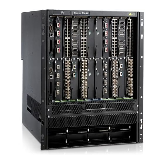
- Page 16 Hardware features FIGURE 3 BigIron RX-16 chassis Interface slot 1 Interface slot 13 Interface slot 2 Interface slot 14 Interface slot 3 Interface slot 15 Interface slot 4 Interface slot 16 Interface slot 5 Switch fabric slot 1 Interface slot 6 Switch fabric slot 2 Interface slot 7 Switch fabric slot 3...
- Page 17 Hardware features FIGURE 4 BigIron RX-32 chassis 3 5 7 13 15 2 4 6 8 14 16 17 19 21 23 37 39 25 27 29 31 18 20 22 24 38 42 40 26 28 30 32 AC OK AC OK AC OK AC OK...
- Page 18 Hardware features Interface slot 8 Interface slot 26 ESD strap connector Interface slot 9 Interface slot 27 Power supply 1 Interface slot 10 Interface slot 28 Power supply 2 Interface slot 11 Interface slot 29 Power supply 3 Interface slot 12 Interface slot 30 Power supply 4 Interface slot 13...
-
Page 19: Bigiron Rx
Hardware features • Up to three switch fabric modules. • Up to eight interface modules. • Up to four power supplies (AC or DC). Before installing any modules or power supplies, you must remove the slot blank or blank power supply faceplate, respectively. -
Page 20: Management Modules
Hardware features CAUTION If you do not install a module in a slot, you must keep the slot blank in place. If you run the chassis with an uncovered slot, the system may overheat. Figure Figure Figure 3, and Figure 4 show the BigIron RX Series chassis and the slots into which you install the various modules. -
Page 21: Console Port
Hardware features Figure 5 shows the management module’s front panel. FIGURE 5 Management module front panel 10/100/1000 Console Port 1 Port 2 Active RX-BI-MR The front panel includes the following control features: • Two PCMCIA slots • A Console port •... -
Page 22: Interface Modules
Hardware features LEDs Table 1 describes the LEDs on the management module’s front panel. TABLE 1 Management module LEDs Position State Meaning Port 1 Each adjacent to On or blinking You have inserted a PCMCIA flash card in a slot or initiated the PCMCIA slot a task related to the file management system on a flash Port 2... -
Page 23: 2-Port 10 Gigabit Ethernet Module
Hardware features 2-port 10 Gigabit Ethernet module Figure 6 shows the 2-port 10 Gigabit Ethernet module’s front panel with XFP modules installed. FIGURE 6 2-port 10 Gigabit Ethernet module front panel The front panel includes the following control features: • Four LEDs •... -
Page 24: 16-Port 10 Gigabit Ethernet Oversubscribed Module
Hardware features TABLE 3 10 Gigabit Ethernet module LEDs Position State Meaning Link Left of each A link is established with the remote port. Ethernet port A link is not established with the remote port. Active Left of each On or blinking The port is transmitting and receiving packets. -
Page 25: Bigiron Rx
Hardware features TABLE 4 10 Gigabit Ethernet module LEDs Position State Meaning Link Below each A link is established with the remote port. Ethernet port A link is not established with the remote port. Active Below each On or blinking The port is transmitting and receiving packets. -
Page 26: Gigabit Ethernet Interface Module (Sfp)
Hardware features The following optic modules versions are available from Brocade: • Short wavelength (86 – 300 meters) – Brocade part number 10G-XFP-SR • Long wavelength (10 kilometers) – Brocade part number 10G-XFP-LR • Extra long wavelength (40 kilometers) – Brocade part number 10G-XFP-ER Gigabit Ethernet interface module (SFP) The 24-port 1 Gigabit Ethernet mini-GBIC (or SFP) is auto-sensing, auto-negotiating Ethernet port and will select the FE or GE mode of operation based on the link signal received. -
Page 27: 48-Port 1 Gigabit Ethernet Interface Module
Hardware features Gigabit Ethernet interface module (RJ-45) Figure 9 shows the 24-port 1 Gigabit Ethernet module’s front panel. FIGURE 9 24-port 1 Gigabit Ethernet module front panel The front panel includes the following control features: • LEDs • 24 1-Gigabit Ethernet ports TABLE 6 Gigabit Ethernet module LEDs Position... -
Page 28: Switch Fabric Module
Hardware features The front panel includes eight Mini RJ-21 Connectors that support six 10/100/1000 Gigabit Ethernet ports each. Figure 10 shows the ports that are supported per RJ-21 connector. A cable connects from the RJ-21 connector on the interface module to a Mini RJ-21 connector on a patch panel. -
Page 29: Power Supplies
Hardware features FIGURE 11 Switch fabric module front panel Active BI-SWF The front panel includes two LEDs, which Table 7 describes. TABLE 7 Switch fabric module LEDs Position State Meaning Above Active LED The module is receiving power. The module is not receiving power. Active Below Pwr LED The chassis switch fabric is active and ready... -
Page 30: Cooling System
Hardware features Each power supply has three LEDs on its faceplate that provide status for the input power, output power and notification of alarms sent. If the input power and output power LEDs are on (a steady green), the power supply is providing power to the chassis components. The power supplies are hot swappable, which means you can remove and replace them without powering down the system. - Page 31 Hardware features FIGURE 12 Fan component locations for the BigIron RX-4 Fan module FIGURE 13 Fan component locations for the BigIron RX-8 Fan module BigIron RX Installation Guide 53-1001811-01...
- Page 32 Hardware features FIGURE 14 Front fan component locations for the BigIron RX-16 Front fan assembly FIGURE 15 Rear fan component locations for the BigIron RX-16 Fan modules BigIron RX Installation Guide 53-1001811-01...
- Page 33 Hardware features FIGURE 16 Rear fan component locations for the BigIron RX-32 Fan module 1 Fan module 6 Fan module 2 Fan module 7 Fan module 3 Fan module 8 Fan module 4 Fan module 9 Fan module 5 Fan module 10 Upon system startup, the fans in the BigIron RX Series switches operate at high speed, then the management module lowers the fan speed to low speed.
-
Page 34: Leds
Hardware features By default, the BigIron RX Series switch polls the temperature sensor on each module every 60 seconds to get a temperature reading. Depending on the temperature readings for the modules, the system can do the following: • Leave the fan speed as is •... -
Page 35: Supported Software Features
Supported software features • BigIron RX-16 – up to 3 BigIron RX-16 chassis • BigIron RX-8 – up to 6 BigIron RX-8 chassis • BigIron RX-4 – up to 10 BigIron RX-4 chassis Supported software features For a complete list of software features supported on the BigIron RX Series switch, refer to the software release notes for this device. - Page 36 Supported software features BigIron RX Installation Guide 53-1001811-01...
-
Page 37: In This Chapter
Chapter Installing a BigIron RX Series Switch In this chapter • Installation precautions ......... 25 •... -
Page 38: General Precautions
Installation precautions General precautions DANGER All fiber-optic interfaces use Class 1 Lasers. CAUTION Do not install the device in an environment where the operating ambient temperature might exceed 40o C (104o F). CAUTION Make sure the air flow around the front, sides, and back of the device is not restricted. CAUTION If you do not install a module in a slot, you must keep the slot blank in place. - Page 39 Installation precautions DANGER Make sure that the power source circuits are properly grounded, then use the power cord supplied with the device to connect it to the power source. DANGER If the installation requires a different power cord than the one supplied with the device, make sure you use a power cord displaying the mark of the safety agency that defines the regulations for power cords in your country.
-
Page 40: Installing A Bigiron Rx-4 Switch
Installing a BigIron RX-4 switch CAUTION For a DC system, the gauge of wire will be determined by the power source as well as the power supply draw (refer to Table 9). Use a grounding wire of at least 6 American Wire Gauge (AWG). The AWG wire should be attached to an agency-approved crimp connector (provided on the BigIron RX Series chassis), crimped with the proper tool. -
Page 41: Preparing The Installation Site
Installing a BigIron RX-4 switch • “Installing a BigIron RX-4 chassis in a rack” • “Installing BigIron RX-4 modules” • “Installing power supplies in a BigIron RX-4 chassis” • “Connecting AC power to a BigIron RX-4 chassis” • “Connecting DC power to a BigIron RX-4 chassis” •... -
Page 42: Chassis Lifting Guidelines For Bigiron Rx-4 Switches
Installing a BigIron RX-4 switch Chassis lifting guidelines for BigIron RX-4 switches DANGER A fully-populated BigIron RX-4, chassis is heavy. TWO OR MORE PEOPLE ARE REQUIRED WHEN LIFTING, HANDLING, OR MOUNTING THESE DEVICES. Follow these guidelines for lifting and moving a BigIron RX-4 chassis: •... - Page 43 Installing a BigIron RX-4 switch To perform this task, you need a #2 Phillips-head screwdriver. FIGURE 17 Removing the extra screws used for shipment Chassis front Chassis rear Shipping screws Mounting a BigIron RX-4 chassis in a rack Follow the steps given below to mount a BigIron RX-4 chassis in a rack. 1.
- Page 44 Installing a BigIron RX-4 switch 3. Starting with the chassis that you want to mount in the lowest position in the rack, mount the chassis in the rack as shown in Figure 19. With two or more people lifting the chassis, slip the wide portion of each keyhole slot over the corresponding screw in the rack.
-
Page 45: Installing Bigiron Rx-4 Modules
Installing a BigIron RX-4 switch Although the slot blanks are different in size, the procedure for removing them from the BigIron RX-4 chassis is the same. Therefore, this section provides one procedure that applies to all slot blanks. You will need a flat-head screwdriver to perform this task. Follow the steps given below to remove a slot blank. - Page 46 Installing a BigIron RX-4 switch • An ESD wrist strap with a plug for connection to the ESD connector on the BigIron RX-4 chassis. DANGER For safety reasons, the ESD wrist strap should contain a 1 meg ohm series resistor. •...
-
Page 47: Installing Power Supplies In A Bigiron Rx-4 Chassis
Installing a BigIron RX-4 switch Installing power supplies in a BigIron RX-4 chassis The BigIron RX-4 accommodates three power supplies (AC or DC) with one required and two redundant. It is shipped with one power supply. You must purchase one or two additional power supplies if you want your BigIron RX-4 equipped for redundancy. -
Page 48: Connecting Ac Power To A Bigiron Rx-4 Chassis
Installing a BigIron RX-4 switch Connecting AC power to a BigIron RX-4 chassis AC power is supplied through an AC power cord that is installed at the rear of the BigIron RX-4 chassis. 1. At the rear of the BigIron RX-4 chassis locate the power receptacle on the left side of the AC power supply. -
Page 49: Final Steps
Installing a BigIron RX-4 switch Follow the steps given below to connect a DC power source. NOTE The layout of the LEDs on your BigIron RX-4 DC power supply may be different from what is shown Figure 23, due to multiple vendors; but the function is the same. 1. -
Page 50: Installing A Bigiron Rx-8 Switch
Installing a BigIron RX-8 switch Installing a BigIron RX-8 switch This section describes the following tasks: • “Preparing the installation site” • “Unpacking a BigIron RX-8 switch” • “Chassis lifting guidelines for BigIron RX-8 switches” • “Installing the BigIron RX-8 chassis in a rack” •... -
Page 51: Chassis Lifting Guidelines For Bigiron Rx-8 Switches
Installing a BigIron RX-8 switch Follow the steps given below to unpack a BigIron RX-8 chassis. 1. Move the pallet to a staging area as close to the installation site as possible. 2. Position the shipping carton with the arrows pointing up. 3. - Page 52 Installing a BigIron RX-8 switch To perform this task, you need a #2 Phillips-head screwdriver. FIGURE 25 Removing the extra screws used for shipment Chassis front Shipping screws Chassis rear Mounting a BigIron RX-8 chassis in a rack Follow the steps given below to mount a BigIron RX-8, chassis in a rack. 1.
- Page 53 Installing a BigIron RX-8 switch 3. Starting with the chassis that you want to mount in the lowest position in the rack, mount the chassis in the rack as shown in Figure 27. With two or more people lifting the chassis, slip the wide portion of each keyhole slot over the corresponding screw in the rack.
-
Page 54: Installing Bigiron Rx-8 Modules
Installing a BigIron RX-8 switch Although the slot blanks are different in size, the procedure for removing them from the BigIron RX-8 chassis is the same. Therefore, this section provides one procedure that applies to all slot blanks. You will need a flat-head screwdriver to perform this task. Follow the steps given below to remove a slot blank. - Page 55 Installing a BigIron RX-8 switch Before installing a module in the BigIron RX-8 chassis, have the following on hand: • An ESD wrist strap with a plug for connection to the ESD connector on the BigIron RX-8 chassis. DANGER For safety reasons, the ESD wrist strap should contain a 1 meg ohm series resistor. •...
-
Page 56: Installing Power Supplies In The Bigiron Rx-8 Chassis
Installing a BigIron RX-8 switch Installing power supplies in the BigIron RX-8 chassis The BigIron RX-8 accommodates three power supplies (AC or DC) with one required and two redundant. It is shipped with one power supply. You must purchase one or two additional power supplies if you want your BigIron RX-8 equipped for redundancy. -
Page 57: Connecting Ac Power To A Bigiron Rx-8 Chassis
Installing a BigIron RX-8 switch For information about connecting power to the chassis, refer to “Connecting AC power to a BigIron RX-8 chassis” on page 45, or “Connecting DC power to a BigIron RX-8 chassis” page 46. Connecting AC power to a BigIron RX-8 chassis AC power is supplied through an AC power cord that is installed at the rear of the BigIron RX-8 chassis. -
Page 58: Connecting Dc Power To A Bigiron Rx-8 Chassis
Installing a BigIron RX-8 switch Connecting DC power to a BigIron RX-8 chassis You can use a DC power source for the BigIron RX-8 chassis. This is supported through use of a DC-to-DC power supply. DC power must be supplied at 48 V and 30 A. The DC-to-DC supply provides the DC power to the chassis at 12 V and 100 A. -
Page 59: Final Steps
Installing a BigIron RX-16 switch Final steps Follow the steps listed below to complete the installation: • “Attaching a management station” • “Powering-on the power source” • “Verifying proper operation” Installing a BigIron RX-16 switch This section describes the following tasks: •... -
Page 60: Unpacking A Bigiron Rx-16 Switch
Installing a BigIron RX-16 switch Unpacking a BigIron RX-16 switch The BigIron RX-16 switch ships with several items. Review the list below, and verify the contents. If any items are missing, contact the place of purchase: • BigIron RX-16 chassis with the appropriate number of switch fabric modules already installed in the slot marked SF and a slot blank installed in all other module slots. -
Page 61: Installing A Bigiron Rx-16 Chassis In A Rack
Installing a BigIron RX-16 switch Installing a BigIron RX-16 chassis in a rack Preparing to mount a BigIron RX-16 chassis in a rack Keep the following in mind when mounting a BigIron RX-16 chassis in a rack: DANGER A fully-populated BigIron RX-16 chassis is heavy. TWO OR MORE PEOPLE ARE REQUIRED WHEN LIFTING, HANDLING, OR MOUNTING THESE DEVICES. - Page 62 Installing a BigIron RX-16 switch Mounting a BigIron RX-16 chassis in a rack Follow the steps given below to mount a BigIron RX-16 chassis in a rack. 1. Determine the position of each chassis in the rack, for example, a chassis with the fewest modules on top, a chassis with more modules than the top chassis in the middle, and a fully populated chassis on the bottom.
- Page 63 Installing a BigIron RX-16 switch FIGURE 34 Mounting the BigIron RX-16 or BigIron RX-32 chassis in a rack 4. Slide the chassis down so that the screw heads are in the narrow portion of the keyhole slots. 5. Tighten the screws to secure the chassis in place. NOTE To provide better grounding of the chassis to the rack, attach the chassis to the rack using star washers.
-
Page 64: Installing Bigiron Rx-16 Modules
Installing a BigIron RX-16 switch Installing BigIron RX-16 modules This section provides one procedure that applies to all modules. The sequence for installing more than one module is important to ensure proper fit. For the BigIron RX-16 chassis, starting with the lowest row, and moving upwards, install the modules left-to-right starting with the bottom row NOTE The BigIron RX Series modules are dedicated, which means that you must install them in the BigIron... - Page 65 Installing a BigIron RX-16 switch 3. With the ejectors in the outward position, insert the module into the appropriate chassis slot and slide the card along the card guide until the ejectors on either side of the module move close to the module front panel. Refer to special instructions, “Populating a BigIron RX-16 chassis”...
-
Page 66: Installing Power Supplies In A Bigiron Rx-16 Chassis
Installing a BigIron RX-16 switch Rules for populating a BigIron RX-16 chassis 1. Install a management module in management slot 2. 2. Install interface modules in interface slots 2, 4, 6, and 8. 3. Install switch fabric modules in the switch fabric slots 2 and 4. 4. -
Page 67: Connecting Ac Power To A Bigiron Rx-16 Chassis
Installing a BigIron RX-16 switch CAUTION Carefully follow the mechanical guides on each side of the power supply slot and make sure the power supply is properly inserted in the guides. Never insert the power supply upside down. 4. After the power supply is fully inserted, push the power supply front panel toward the back of the chassis. -
Page 68: Connecting Dc Power To A Bigiron Rx-16 Chassis
Installing a BigIron RX-16 switch DANGER If the installation requires a different power cord than the one supplied with the device, make sure you use a power cord displaying the mark of the safety agency that defines the regulations for power cords in your country. The mark is your assurance that the power cord can be used safely with the device. -
Page 69: Final Steps
Installing a BigIron RX-32 switch FIGURE 39 Crimping the power supply wire in the lug #8 AWG power supply wire 4. Re-attach the transparent cover over the power supply lugs that was removed in Step 1. 5. Connect the wire to your DC power source, making sure to connect the -48V cable to the negative terminal on the power supply and the 0V cable to the positive terminal as marked on the power supply. -
Page 70: Unpacking A Bigiron Rx-32 Switch
Installing a BigIron RX-32 switch Installation location Before installing the switch, plan its location and orientation relative to other devices and equipment. For cooling purposes, allow a minimum of six inches of space between the sides, front, and the back of the chassis and walls or other obstructions. If a chassis is installed within a perforated enclosure, the perforations must have openings of at least 60 percent of the surface. -
Page 71: Installing A Bigiron Rx-32 Chassis In A Rack
Installing a BigIron RX-32 switch The BigIron RX-32 chassis ships in a wooden crate, bolted to an inner pallet, and resting on an outer pallet. Follow the steps given below to uncrate the chassis. NOTE To uncrate the BigIron RX-32 chassis, the crate must be in the upright (vertical) position. 1. - Page 72 Installing a BigIron RX-32 switch • Mounting a BigIron RX-32 chassis in a rack Preparing to mount a BigIron RX-32 chassis in a rack Keep the following in mind when mounting a BigIron RX-32 chassis in a rack: DANGER Make sure the rack or cabinet housing the device is adequately secured to prevent it from becoming unstable or falling over.
- Page 73 Installing a BigIron RX-32 switch Follow the steps given below to install a BigIron RX-32 chassis. 1. Ensure the rack is in its permanent location and is secured to the building. Ensure that the installation site allows adequate clearance for both airflow, installation, and maintenance. 2.
-
Page 74: Installing Bigiron Rx-32 Modules
Installing a BigIron RX-32 switch 10. If you are installing the chassis in a four-post rack or cabinet, install a mounting screw and a cage nut into each of the holes aligned with the threaded holes in the spacer bars. If you are installing the chassis in an open-frame rack, install four standard #12-24 pan-head screws into the keyhole mounting holes aligned with the rack. - Page 75 Installing a BigIron RX-32 switch NOTE When inserting the module into the chassis, make sure that the faceplate doesnot overlap with the faceplate of an adjacent interface module. 5. Push the ejectors in until they are flush with the module front panel. This action will fully seat the module in the backplane.
- Page 76 Installing a BigIron RX-32 switch BigIron RX-32 module installation details NOTE Do not insert interface modules running releases below 02.3.00 into slots 17 to 32 of a BigIron RX-32 chassis. They should only be inserted into slots 1 to 16. NOTE Any empty slots must contain slot blanks to ensure proper air flow within the chassis.
- Page 77 Installing a BigIron RX-32 switch FIGURE 43 BigIron RX-32 chassis 3 5 7 13 15 2 4 6 8 14 16 17 19 21 23 37 39 25 27 29 31 18 20 22 24 38 42 40 26 28 30 32 AC OK AC OK AC OK...
- Page 78 Installing a BigIron RX-32 switch Interface slot 8 Switch fabric slot 2 Interface slot 9 Switch fabric slot 3 Interface slot 10 Switch fabric slot 4 Interface slot 11 Switch fabric slot 5 Interface slot 12 Switch fabric slot 6 Interface slot 13 Switch fabric slot 7 Interface slot 14...
-
Page 79: Bigiron Rx-32 Cable Routing
Installing a BigIron RX-32 switch When using the tool to extract the boot or plug of a modular connector, cover the entire length of the boot or plug with the tool. Notice that one end of the tool has a "hook" side. Use this side to compress the locking tab while you remove the connector. - Page 80 Installing a BigIron RX-32 switch Details of cable routing are as follows: CAUTION Be sure not to exceed the minimum recommended bend radius for the cables: 2 in. for MRJ-21 cables, and 1.5 in. for Category 5 (RJ-45) and fiber-optic cables. Cable routing for the upper-left quadrant Route slot cards in the numerical order starting with the cables of Slot Card #1.
- Page 81 Installing a BigIron RX-32 switch FIGURE 47 Routing upper-left quadrant cables up Upper left quadrant Comb B (Slot #5 and #6 cables) Comb C (Slot #7 and #8 cables) Comb A (Slot #3 and #4 cables) 2. Route slot card #3 and #4 cables up through Comb A. Refer to Figure 3.
- Page 82 Installing a BigIron RX-32 switch Cable routing for the upper-right quadrant Route slot cards in the numerical order starting with the cables of Slot Card #15. 1. Route slot card #15 and #16 cables directly to the right through the side comb. Refer to Figure FIGURE 48 Routing upper-right quadrant cables to the right...
- Page 83 Installing a BigIron RX-32 switch FIGURE 49 Routing upper-right quadrant cables up Upper right quadrant Comb B (Slot #11 and #12 cables) Comb C (Slot #9 and #10 cables) Comb A (Slot #13 and #14 cables) 2. Route slot card #13 and #14 cables up through Comb A. Refer to Figure 3.
- Page 84 Installing a BigIron RX-32 switch Cable routing for the lower-left quadrant 1. Route slot card #18 and #17 cables directly to the left through the side comb. Refer to Figure FIGURE 50 Routing lower-left quadrant cables to the left Lower left quadrant Cables from slot #18 Cables from slot #17 Side combs (18)
- Page 85 Installing a BigIron RX-32 switch FIGURE 51 Routing lower-left quadrant cables down Lower left quadrant Comb B (Slot #21 and #22 cables) Comb A (Slot #19 and #20 cables) Comb C (Slot #23 and #24 cables) 2. Route slot card #20 and #19 cables down through Comb A. Refer to Figure 3.
- Page 86 Installing a BigIron RX-32 switch Cable routing for the lower-right quadrant 1. Route slot card #32 and #31 cables directly to the right through the side comb. Refer to Figure FIGURE 52 Routing the lower-right quadrant cables to the right Lower right quadrant Cables from slot #32 Cables from slot #31...
-
Page 87: Installing Power Supplies In A Bigiron Rx-32 Chassis
Installing a BigIron RX-32 switch FIGURE 53 Routing lower-right quadrant cables down Lower right quadrant Comb B (Slot #27 and #28 cables) Comb A (Slot #29 and #30 cables) Comb C (Slot #25 and #26 cables) 2. Route slot card #30 and #29 cables down through Comb A. Refer to Figure 3. - Page 88 Installing a BigIron RX-32 switch FIGURE 54 Installing a power supply in a BigIron RX-32 chassis AC OK DC OK Power supply indicators Latch handle locked AC OK Power supply blank cover DC OK Pull down on plunger to remove Power supply Latch handle open CAUTION...
-
Page 89: Connecting Ac Power To A Bigiron Rx-32 Chassis
Attaching a management station 6. Gently pull the release latch on the power supply front panel upward and toward the top of the power supply front panel. This action locks the power supply in place. For information about connecting power to the chassis, refer to “Connecting AC power to a BigIron RX-32 chassis”... -
Page 90: Attaching A Pc Or Terminal To The Console Port Or Ethernet Port
Attaching a management station • You can connect the BigIron RX Series switch to your existing management network and manage the switch, along with other network devices, from a management station. To do this, you must connect the management module’s 10BaseT/100BaseTX/1000BaseTX Ethernet (management) port to an Ethernet network. -
Page 91: Attaching The Management Module's Ethernet Port
Powering-on the power source Attaching the management module’s Ethernet Port to a network The management module’s 10BaseT/100BaseTX/1000BaseTX Ethernet (management) port (RJ-45 UTP connector) allows you to connect the management port to a network. A management station in your existing management network can then access a BigIron RX Series switch using the IronView Network Manager. -
Page 92: Verifying Proper Operation
Verifying proper operation Insert the other end into a 115V or 120V wall outlet. Repeat this step for each installed AC power supply. DANGER If the installation requires a different power cord than the one supplied with the device, make sure you use a power cord displaying the mark of the safety agency that defines the regulations for power cords in your country. - Page 93 Verifying proper operation TABLE 13 Desired and abnormal LED states after system power on Desired state Meaning Abnormal Meaning or action state Management module Active The Active LED on The module is Neither of the management one of the installed functioning as the modules is managing the switch management...
- Page 94 Verifying proper operation TABLE 13 Desired and abnormal LED states after system power on (Continued) Desired state Meaning Abnormal Meaning or action state Interface module The module is The module is not receiving power. receiving power. You can do the following: •...
- Page 95 Verifying proper operation TABLE 13 Desired and abnormal LED states after system power on (Continued) Desired state Meaning Abnormal Meaning or action state Link A link is established At this stage of the installation, with the remote port. you have not yet cabled the interface module ports, so this LED will be off.
- Page 96 Verifying proper operation TABLE 13 Desired and abnormal LED states after system power on (Continued) Desired state Meaning Abnormal Meaning or action state DC OK Green (steady) The power supply is The power supply is not supplying providing DC power to power to the chassis.
-
Page 97: Displaying The Module Status
Verifying proper operation TABLE 13 Desired and abnormal LED states after system power on (Continued) Desired state Meaning Abnormal Meaning or action state Fan control module (two LEDs on rear panel of chassis) Unlabeled Green (steady) The fans are working Off or amber The fans are not receiving power and responding to... - Page 98 Verifying proper operation If you do not see this prompt, do the following. 1. Make sure the cable is securely connected to your PC or terminal and the Console port or Ethernet port. 2. Check the settings in your terminal emulation program. In addition to the session settings listed in “Attaching a PC or terminal to the Console port or Ethernet port”...
- Page 99 Verifying proper operation • CARD_STATE_FAILED – The management module was unable to bring up an interface module properly. If you observe this status, make certain that the interface module is installed properly. For more information, refer to “Installing BigIron RX-4 modules” on page 33, “Installing BigIron RX-8 modules”...
- Page 100 Verifying proper operation BigIron RX Installation Guide 53-1001811-01...
-
Page 101: In This Chapter
Chapter Using the Brocade Structured Cabling Components In this chapter • Cable Cinch overview ......... . . 89 •... -
Page 102: Mrj-21 Procedures
mRJ-21 procedures mRJ-21 procedures The following procedure demonstrates securing up to eight RJ-21 cables into the Cable CInch. When securing fewer than the maximum cables, follow the procedure to secure the desired number of cables and simply wrap the remaining Velcro strap around the Cable CInch. Use the additional slots in the clip to secure groups of cables as required. -
Page 103: Cable Cinch With Three Mrj-21 Cables
mRJ-21 procedures Cable Cinch with three mRJ-21 cables Three mRJ-21 cables may be secured as shown in Figure FIGURE 58 Three mRJ-21 cables Cable Cinch with four mRJ-21 cables Four mRJ-21 cables may be secured as shown in Figure FIGURE 59 Four mRJ-21 cables BigIron RX Installation Guide 53-1001811-01... -
Page 104: Cable Cinch With Five Mrj-21 Cables
mRJ-21 procedures Cable Cinch with five mRJ-21 cables Five mRJ-21 cables may be secured as shown in Figure FIGURE 60 Five mRJ-21 cables Cable Cinch with six mRJ-21 cables Six mRJ-21 cables may be secured as shown in Figure FIGURE 61 Six mRJ-21 cables BigIron RX Installation Guide 53-1001811-01... -
Page 105: Cable Cinch With Seven Mrj-21 Cables
mRJ-21 procedures Cable Cinch with seven mRJ-21 cables Seven mRJ-21 cables may be secured as shown in Figure FIGURE 62 Seven mRJ-21 cables Cable Cinch with eight mRJ-21 cables Eight mRJ-21 cables may be secured as shown in Figure FIGURE 63 Eight mRJ-21 cables BigIron RX Installation Guide 53-1001811-01... -
Page 106: Rj-45 Procedures
RJ-45 procedures RJ-45 procedures Use the following guidelines when using the cable cinch clips with RJ-45 cables. Cable Cinch with one group of RJ-45 cables RJ-45 cables may be secured in groups of six. To secure up to six RJ-45 cables in one group, place the Velcro strap through slot one and use the front left recesses as shown in Figure FIGURE 64... -
Page 107: Cable Cinch With Three Groups Of Rj-45 Cables
RJ-45 procedures Cable Cinch with three groups of RJ-45 cables 18 RJ-45 cables, in three groups, may be secured as shown in Figure FIGURE 66 18 RJ-45 cables in three groups Cable Cinch with four groups of RJ-45 cables 24 RJ-45 cables, in four groups, may be secured as shown in Figure FIGURE 67 24 RJ-45 cables in four groups... -
Page 108: Cable Cinch With Five Groups Of Rj-45 Cables
RJ-45 procedures Cable Cinch with five groups of RJ-45 cables 30 RJ-45 cables, in five groups, may be secured as shown in Figure FIGURE 68 30 RJ-45 cables in five groups Cable Cinch with six groups of RJ-45 cables 36 RJ-45 cables, in six groups, may be secured as shown in Figure FIGURE 69 36 RJ-45 cables in six groups... -
Page 109: Cable Cinch With Seven Groups Of Rj-45 Cables
RJ-45 procedures Cable Cinch with seven groups of RJ-45 cables 42 RJ-45 cables, in seven groups, may be secured as shown in Figure FIGURE 70 42 RJ-45 cables in seven groups Cable Cinch with eight groups of RJ-45 cables 48 RJ-45 cables, in eight groups, may be secured as shown in Figure FIGURE 71 48 RJ-45 cables in eight groups... - Page 110 RJ-45 procedures BigIron RX Installation Guide 53-1001811-01...
-
Page 111: Connecting A Bigiron Rx Series Switch To A Network Device
Chapter Connecting a BigIron RX Series Switch to a Network Device In this chapter • Assigning passwords ..........99 •... -
Page 112: Password History
Assigning passwords There are no new CLI commands for this feature. Login lockout The CLI provides up to three login attempts. If a user fails to login after three attempts, that user is locked out (disabled). To re-enable the user, do one of the following: •... - Page 113 Assigning passwords • Privileged EXEC – This level is also called the Enable level and can be secured by a password. You can perform tasks such as manage files on the management module’s flash memory or a PCMCIA flash card in the management module’s slots 1 or 2, save the system configuration to flash memory, and clear caches at this level.
-
Page 114: Configuring Ip Addresses
Configuring IP addresses Configuring IP addresses The BigIron RX Series switches implement separate data and control planes. This architecture affects how you assign IP addresses. Table 14 outlines the interfaces to which you can assign IP addresses. In this table, “in band” refers to an interface over which user packets are routed, while “out of band”... -
Page 115: Assigning An Ip Address To An Interface, Virtual Interface, Or Loopback
Configuring IP addresses For example, to assign the IP address 10.0.1.1 to the management interface, do the following: 1. At the opening CLI prompt, enter enable. BigIron RX> enable 2. Enter the following command at the Privileged EXEC level prompt (for example, BigIron RX#), then press Enter. -
Page 116: Enabling And Disabling The Interfaces
Configuring IP addresses For example, to assign the IP address 192.22.3.44 and sub-net mask 255.255.255.0 to Ethernet interface 1/1, do the following. 1. At the opening CLI prompt, enter enable. BigIron RX> enable 2. Enter the following command at the Privileged EXEC level prompt, then press Enter. This command erases the factory test configuration if still present: BigIron RX# erase startup-config CAUTION... -
Page 117: Understanding How The Management Port Functions
Understanding how the management port functions Syntax: disable Understanding how the management port functions You must be aware of how the BigIron RX Series system’s management port functions as described in the following: • The management port allows you to configure, monitor, and manage the BigIron RX Series system only. -
Page 118: Installing A Fiber Optic Module
Connecting a BigIron RX Series switch TABLE 15 Fiber optic modules and cabling (Continued) Fiber optic modules (PMD) Distance Fiber optic cabling Brocade part number Long wavelength 10 km 9/125 micron single-mode fiber with LC 10G-XFP-LR 1310 nm serial connectors Extra long wavelength 40 km 9/125 micron single-mode fiber with LC... -
Page 119: Cabling A Fiber Optic Module
Connecting a BigIron RX Series switch 4. Gently insert the fiber optic module into the port until the module clicks into place. The fiber optic modules are keyed to prevent incorrect insertion. Cabling a fiber optic module To cable a fiber optic module, do the following. 1. -
Page 120: Cleaning Fiber Optic Modules
Connecting a BigIron RX Series switch You can view the optical monitoring information using the show optic command as displayed in the following: BigIron RX#show optic 4 Port Temperature Tx Power Rx Power Tx Bias Current Monitor +----+-----------+--------------+--------------+---------------+-------+ 30.8242 C -001.8822 dBm -002.5908 dBm 41.790 mA Normal... -
Page 121: Troubleshooting Network Connections
Connecting a BigIron RX Series switch Troubleshooting network connections After you cable the fiber optic modules, you can observe certain LEDs to determine if the network connections are functioning properly. Table 16 outlines the LEDs related to the network connections, the desired state of each LED, possible abnormal states of each LED, and what to do if an LED indicates an abnormal state. -
Page 122: Testing Network Connectivity
Testing network connectivity Testing network connectivity After you cable the fiber optic modules, you can test connectivity to other network devices by pinging those devices. You also can perform trace routes. To resolve problems that may arise with network connections: •... -
Page 123: Using Virtual Cable Testing To Diagnose A Cable
Testing network connectivity Refer to the BigIron RX Series Configuration Guide for information about the command syntax. Using virtual cable testing to diagnose a cable BigIron RX devices support Virtual Cable Test (VCT) technology. VCT technology enables you to diagnose a conductor (wire or cable) by sending a pulsed signal into the conductor, then examining the reflection of that pulse. - Page 124 Testing network connectivity TABLE 17 Cable statistics This line... Displays... Port The interface that was tested. Speed The port’s current line speed. Local pair The local link name. Pair Length The cable length when terminated, or the distance to the point of fault when the line is not up.
-
Page 125: In This Chapter
Chapter Managing the BigIron RX Series Chassis and Modules In this chapter • Managing the BigIron RX Series chassis ......113 •... - Page 126 Managing the BigIron RX Series chassis To display this information, enter the following command at any level of the CLI: BigIron RX# show chassis *** BigIron RX-4 CHASSIS *** ---POWERS --- AC Powers Are Used. Power 1: Installed (OK) Power 2: not present Power 3: not present Slot Power-On Priority: Slot1 (pri=1)
-
Page 127: Displaying The Syslog Configuration And Static And Dynamic Buffers
Managing the BigIron RX Series chassis TABLE 18 Chassis status and temperature information (Continued) This field... Displays... Status The status of a fan can be one of the following: • OK – The fan is functioning properly and is keeping the temperature of each module within an acceptable temperature range. - Page 128 Managing the BigIron RX Series chassis TABLE 19 Syslog buffer configuration (Continued) This field... Displays... flushes The number of times the Syslog buffer has been cleared by the clear logging command. For information about clearing the Syslog buffer, refer “Static and dynamic buffers” on page 116.
-
Page 129: Managing The Cooling System
Managing the cooling system Syntax: clear logging [dynamic-buffer | static-buffer] You can specify the dynamic-buffer keyword to clear the dynamic buffer or the static-buffer keyword to clear the static buffer. If you do not specify a buffer, both buffers are cleared. Managing the cooling system This section provides configuration, management, and monitoring information about the BigIron RX Series cooling system. - Page 130 Managing the cooling system • If the temperature of a management module, the switch fabric module, and all interface modules falls below the low threshold for a fan speed, the fan decreases its speed to the next lower speed. If the temperature of all modules falls below the high threshold for the low speed, the fan operates at the low speed.
- Page 131 Managing the cooling system Syntax: fan-threshold <module> [low <high-threshold>] [med <low-threshold> <high-threshold>] [med-hi <low-threshold> <high-threshold>] [hi <low-threshold> <high-threshold>] For the <module> parameter, you can specify the following: • lp – Changes low and high temperature thresholds for the interface modules. •...
- Page 132 Managing the cooling system Displaying temperature thresholds for modules and fan speeds To check the current settings of the low and high temperature thresholds for modules and fan speeds, you can enter the following command at any level of the CLI: BigIron RX# show fan-threshold === Thermal Sensor Control Block (THERMAL_SENSOR_TEST_RULE_MP) === Fan Speed Low: -1 - 60...
-
Page 133: Manually Setting The Fan Speed
Managing the cooling system The display shows the following information: TABLE 21 Temperature threshold information for modules and fan speeds This field... Displays... Thermal Sensor Control Block The temperature threshold information for the various modules. The (THERMAL_SENSOR_TEST_RULE_<mod <module> parameter indicates the following: •... -
Page 134: Monitoring The Cooling System
Managing the cooling system low – The system sets the fan speed to low. med – The system sets the fan speed to medium. med-high – The system sets the fan speed to medium-high. Monitoring the cooling system You can monitor the following aspects of the BigIron RX Series cooling system: •... -
Page 135: Managing The Interface Modules
Managing the interface modules To display the system log, enter the following command at any CLI level: BigIron RX# show log Syntax: show log Managing the interface modules This section contains the following information: • Configuring interface module boot parameters •... - Page 136 Managing the interface modules The system allows you to manage synchronization of the IronWare images between management and interface modules in the following situations: • You are prompted to synchronize the IronWare images during bootup. • You want to initiate an immediate synchronization; for example, you want an immediate update of the IronWare images on one or all interface modules.
-
Page 137: Specifying An Immediate Boot
Managing the interface modules To disable the automatic check and synchronization during bootup, enter the following command at the global CONFIG level: BigIron RX(config)# lp disable-lp-sync-check Syntax: lp disable-lp-sync-check Provided that you save this configuration by entering the write memory command, the system will disable the automatic check and synchronization of the IronWare images starting with the next software reload or system reset and each reload or reset after that. - Page 138 Managing the interface modules Specifying an immediate boot from the management module’s PCMCIA slots For example, to specify an immediate boot for the interface module installed in slot 1 from the management module’s PCMCIA slot 1, enter the following command at the Privileged EXEC level of the CLI: BigIron RX# lp boot system slot1 primary 1 Syntax: lp boot system slot1 | slot2 <filename>...
- Page 139 Managing the interface modules BigIron RX# lp boot system tftp 123.123.123.123 primary 1 Syntax: lp boot system tftp <ip-address> <filename> <slot-number> The <ip-address> parameter specifies the IP address of the TFTP server from which the interface module will be booted. The <filename>...
- Page 140 Managing the interface modules The all | <slot-number> parameter specifies that the automatic boot applies to all interface modules in the BigIron RX Series chassis or to an interface module in the specified chassis slot number only. You can specify 1 – 4 for BigIron RX-4, 1 – 8 for BigIron RX-8 or 1 – 16 for BigIron RX-16.
-
Page 141: Changing Priority Of Chassis Slots For Interface Modules
Managing the interface modules The all | <slot-number> parameter specifies that the automatic boot applies to all interface modules in the BigIron RX Series chassis or to an interface module in the specified chassis slot number only. You can specify 1 – 4 for BigIron RX-4, 1 – 8 for BigIron RX-8 or 1 – 16 for BigIron RX-16. -
Page 142: Disabling And Reenabling Power To The Interface Modules
Managing the interface modules Disabling and reenabling power to the interface modules If needed, you can disable power to a specified interface module and then reenable it. For example, to disable power to the interface module in chassis slot 1, enter the following command at the Privileged EXEC level of the CLI: BigIron RX# power-off lp 1 Syntax: power-off lp <slot-number>... -
Page 143: Enabling And Disabling Management Module Cpu Usage Calculations
Enabling and disabling management module CPU usage calculations Enabling and disabling management module CPU usage calculations You can enable the BigIron RX Series system to perform usage averaging calculations on tasks handled by the management module’s CPU. If you enable the calculation performance, you can display usage averages for all tasks performed by the management module’s CPU for an interval of up to 1 hour. -
Page 144: Displaying Management Module Cpu Usage
Displaying management module CPU usage Displaying management module CPU usage You can display the tasks handled by the management module and the amount of the management module’s CPU used by each task. To do so, enter the following command at any level of the CLI: BigIron RX# show tasks Task Name... -
Page 145: Enabling And Disabling Packet Logging For Management And Interface Modules
Enabling and disabling packet logging for management and interface modules Enabling and disabling packet logging for management and interface modules You can enable the logging of packets transmitted, received, or both transmitted and received by a management or interface module in the BigIron RX Series chassis. If you enable packet logging, you can display the packet log using the show packet-logging command. -
Page 146: Displaying A Packet Log
Enabling and disabling packet logging for management and interface modules Specify the stop keyword to stop packet logging. NOTE When finished gathering packet logging information for debugging purposes, Brocade recommends disabling the generation of a packet log, which is CPU-intensive and can affect the performance of the management module. -
Page 147: Removing Mac Address Entries
Removing MAC address entries The display shows the following information: TABLE 23 Packet log fields This field... Displays..Total <number> packet records... The total number of packets recorded in the packet log for a specified module. TX or RX TX indicates the packet was transmitted by the module, while RX indicates the packet was received by the module. - Page 148 Removing MAC address entries BigIron RX Installation Guide 53-1001811-01...
-
Page 149: Maintaining A Bigiron Rx Series Switch
Chapter Maintaining a BigIron RX Series Switch In this chapter • Replacing a management module ....... . 137 •... -
Page 150: Removing A Management Module
Replacing a management module NOTE When a management switches over from active (remove active) to standby, it will send out the syslog messages or traps such as PSU failure or LP/SNM removal. This section provides information about the following tasks: •... -
Page 151: Installing A New Management Module
Replacing an interface module Installing a new management module You can install a management module while the BigIron RX Series chassis is powered on and running. NOTE The BigIron RX Series management module is dedicated, which means that you must install it in the BigIron RX Series chassis only. -
Page 152: Removing An Interface Module
Replacing an interface module CAUTION If hot removing or inserting a module, please allow a minimum of two seconds after a module (or power supply or fan tray) has been removed before inserting a module in the same slot. This section provides information about the following tasks: •... -
Page 153: Installing A New Interface Module
Replacing an interface module Installing a new interface module You can install a new interface module while the BigIron RX Series chassis is powered on and running. NOTE A BigIron RX Series interface module is dedicated, which means that you must install it in a BigIron RX Series chassis only. - Page 154 Replacing an interface module BigIron RX# power-off lp <slot number> BigIron RX# power-on lp <slot number> FIGURE 73 Installing a module in a BigIron RX-4 chassis Interface module FIGURE 74 Installing a module in a BigIron RX-8 chassis Interface module BigIron RX Installation Guide 53-1001811-01...
-
Page 155: Replacing A Switch Fabric Module
Replacing a switch fabric module FIGURE 75 Installing a module in a BigIron RX-16 chassis Interface module Replacing a switch fabric module You can remove a switch fabric module while it is powered on and running and replace it with a new one. -
Page 156: Removing A Switch Fabric Module
Replacing a switch fabric module Removing a switch fabric module For a graceful shutdown of the links, Brocade recommends that you disable the switch fabric module before removing it from the BigIron RX Series chassis by following the instructions below. Before removing a switch fabric module from the BigIron RX Series chassis, have the following on hand: •... -
Page 157: Replacing A Fiber-Optic Transceiver
Replacing a fiber-optic transceiver • An ESD wrist strap with a plug for connection to the ESD connector on the BigIron RX Series chassis DANGER For safety reasons, the ESD wrist strap should contain a 1 meg ohm series resistor. •... -
Page 158: Installing A New Fiber-Optic Transceiver
Replacing a fiber-optic transceiver Follow the steps given below to remove a fiber-optic transceiver from a 10 Gigabit Ethernet port. 1. Put on the ESD wrist strap and ground yourself by inserting the plug into the ESD connector located in the upper right corner of the chassis front. 2. -
Page 159: Replacing A Power Supply
Replacing a power supply Replacing a power supply You can replace an power supply while the BigIron RX Series chassis is powered on and running. The power supplies are located in slots along the bottom of the BigIron RX Series chassis. CAUTION If hot removing or inserting a module, please allow a minimum of 2 seconds after a module (or power supply or fan tray) has been removed before inserting a module in the same slot. - Page 160 Replacing a power supply supply. The BigIron RX Series chassis can be running while a power supply is being removed and replaced, but the power supply itself should not be connected to a power source. Otherwise, you could be injured or the power supply or other parts of the device could be damaged. DANGER The front panel of an power supplies include a handle that locks the power supply in the chassis.
- Page 161 Replacing a power supply FIGURE 76 Removing and replacing a BigIron RX-32 power supply AC OK DC OK Power supply indicators Latch handle locked AC OK Power supply blank cover DC OK Pull down on plunger to remove Power supply Latch handle open 6.
-
Page 162: Replacing Cooling System Components
Replacing cooling system components 8. After the power supply is fully inserted, push the power supply front panel toward the back of the chassis until the power supply is fully seated. 9. For the BigIron RX-32, gently pull the handle on the power supply front panel upward and toward the top of the power supply front panel. - Page 163 Replacing cooling system components You can remove and replace a fan assembly while the BigIron RX-32 chassis is powered on and running. CAUTION To avoid overheating of the BigIron RX-32 chassis, remove only one fan assembly at a time, and replace it promptly.
- Page 164 Replacing cooling system components FIGURE 77 Removing a BigIron RX-32 fan assembly Fan module 1 Fan module 6 Fan module 2 Fan module 7 Fan module 3 Fan module 8 Fan module 4 Fan module 9 Fan module 5 Fan module 10 4.
-
Page 165: Replacing Fan Assemblies In The Bigiron Rx-16
Replacing cooling system components Access the CLI, and enter the show chassis command to verify that the fan is operating normally. Replacing fan assemblies in the BigIron RX-16 The BigIron RX-16 has three fan assemblies: one accessible from the front of the chassis and two accessible from the rear. - Page 166 Replacing cooling system components FIGURE 78 Removing a BigIron RX-16 rear fan assembly Power connector Captive screws Fan assembly 4. Insert the new fan into the fan slot and push the enclosure in until the face plate is flush with the chassis.
-
Page 167: Replacing The Fan Assembly In The Bigiron Rx-4 And
Replacing cooling system components 3. Remove the fan assembly from the chassis by grabbing the handle on the fan assembly and pulling it toward you as shown in Figure 79. Pulling the enclosure unseats the fan assembly connector from a chassis connector. DANGER Be careful not to insert your fingers into the fan while removing it from the chassis. - Page 168 Replacing cooling system components NOTE If you did not remove the extra shipment screws from the BigIron RX-4 and BigIron RX-8 chassis during installation (refer to “Removing BigIron RX-4 extra shipment screws” on page 30), then you will not be able to remove the fan tray assembly. In this case, you will have to remove the BigIron RX-4 or BigIron RX-8 from the rack to remove the shipment screws.
- Page 169 Replacing cooling system components FIGURE 80 Removing a fan from a BigIron RX-4 switch Latch release Fan tray assembly FIGURE 81 Removing a fan from a BigIron RX-8 switch Latch release Fan tray assembly 4. Insert the new fan assembly into the fan slot and push the enclosure in until the face plate is flush with the chassis.
-
Page 170: Replacing The Air Filters In A Bigiron Rx Series Switch
Replacing cooling system components 6. Access the CLI, and enter the show chassis command to verify that the fans are operating normally. Replacing the air filters in a BigIron RX Series switch Brocade recommends replacing the air filters in BigIron RX Series switches quarterly. Replacing the filters regularly prevents the accumulation of dust on module components. - Page 171 Replacing cooling system components 1. From the front of the chassis, remove the air inlet cover by unscrewing the four socket head screws with an Allen wrench, as shown in Figure FIGURE 82 BigIron RX-32 air inlet panel Captive screws 2.
- Page 172 Replacing cooling system components FIGURE 83 Air filter removal and replacement for BigIron RX-32 Direction of airflow in chassis Replacing the air filter in the BigIron RX-16 Follow the steps given below to replace the air filter in the BigIron RX-16. 1.
- Page 173 Replacing cooling system components There is a hook on the back of the retainer that is attached to the grab-strap. As you pull the retainer out, the filter is pulled along with it. FIGURE 84 Air filter removal and replacement for BigIron RX-16 Fan tray Filter grap strap Filter...
- Page 174 Replacing cooling system components FIGURE 85 Air filter removal and replacement for BigIron RX-4 Direction of airflow in chassis Filter retainer Filter Fan trap FIGURE 86 Air filter removal and replacement for BigIron RX-8 Direction of airflow in chassis Filter retainer Filter Fan trap 3.
-
Page 175: Upgrading Software Images And Configuration Files
Chapter Upgrading Software Images and Configuration Files In this chapter • Software images required........163 •... -
Page 176: Boot Image
Software images required This section describes each of the software images required to operate a BigIron RX Series switch as described in Table 24. Also, Figure 87 illustrates how each of the files are stored on the management and interface modules. FIGURE 87 Management and interface modules flash images Management Module... -
Page 177: Software Image Naming Conventions
Software image naming conventions FPGA image The FPGA image is named "MBRIDGE" and serves as the interface between the management module and the backplane. It is loaded on the management module only. Startup configuration file The Startup Configuration file contains a default configuration that is loaded at the factory and appended with commands for the user. -
Page 178: Displaying Flash Memory And Version Information
Displaying flash memory and version information Release types XX contains the major release number, for example, 01 or 02. Y contains the minor release number, for example, 1 or 2. ZZ contains the maintenance release number, for example, 00 or 01. x = is an optional field;... - Page 179 Displaying flash memory and version information o LP IronWare Image (Primary for LP Image Type 0) Version 2.5.0T157, Size 2000853 bytes, Check Sum 1e45 Compiled on Oct 20 2007 at 00:05:04 labeled as rlp02500 o LP IronWare Image (Secondary for LP Image Type 0) Version 2.5.0T157, Size 1999406 bytes, Check Sum 04f4 Compiled on Oct 10 2007 at 17:15:40 labeled as rlp02500 o Boot-Monitor Image...
- Page 180 Displaying flash memory and version information Compiled on Oct 20 2007 at 00:05:04 labeled as rlp02500 o IronWare Image (Secondary) Version 2.5.0T157, Size 1999406 bytes, Check Sum 04f4 Compiled on Oct 10 2007 at 17:15:40 labeled as rlp02500 o Boot-Monitor Image Version 2.5.0T155, Size 285248 bytes, Check Sum 5643 Compiled on Oct 19 2007 at 23:08:32 labeled as rlb02500 Boot Flash: Type AM29LV040B, Size 512 KB...
- Page 181 Displaying flash memory and version information TABLE 25 Code flash and boot flash information This field... Displays... Management modules <type> Management Module The management module for which flash information is displayed. (<location>) The <type> parameter indicates an active or standby management module. The <location>...
- Page 182 Displaying flash memory and version information TABLE 25 Code flash and boot flash information (Continued) This field... Displays... Boot-Monitor Image Indicates the monitor image installed in the management module’s code flash. The image name format is described in “Software image naming conventions”...
-
Page 183: Displaying Version Information
Displaying flash memory and version information TABLE 25 Code flash and boot flash information (Continued) This field... Displays... Boot Flash The model number and size of the interface module’s boot flash. Boot-Monitor Image Indicates the boot image installed in the interface module’s boot flash. The image name format is described in “Software image naming conventions”... - Page 184 Displaying flash memory and version information FE 6: Type fe200, Version 2 RX-BI-32-SFM Switch Fabric Module 5 (Serial #: PR40060009, Part #: Not Exist) SBRIDGE Version: 6, CPLD Version: 2 FE 1: Type fe200, Version 2 FE 2: Type fe200, Version 2 FE 3: Type fe200, Version 2...
- Page 185 Displaying flash memory and version information (420184 bytes) from code flash IronWare : Version 2.5.0T143 Copyright (c) 1996-2007 Foundry Networks, Inc. Compiled on Oct 19 2007 at 23:42:24 labeled as rmpr02500 (4141014 bytes) from Primary Board ID : 00 MBRIDGE32 Revision : 18 916 MHz Power PC processor (version 8003/0101) 166 MHz bus 512 KB Boot Flash (AM29LV040B), 32 MB Code Flash (MT28F128J3)
-
Page 186: Upgrading The Bigiron Rx Series Software
Upgrading the BigIron RX Series software (285248 bytes) from boot flash Monitor : Version 2.5.0T155 Copyright (c) 1996-2007 Foundry Networks, Inc. Compiled on Oct 19 2007 at 23:08:32 labeled as rlb02500 (285248 bytes) from code flash IronWare : Version 2.5.0T157 Copyright (c) 1996-2007 Foundry Networks, Inc. Compiled on Oct 20 2007 at 00:05:04 labeled as rlp02500 (2000853 bytes) from Primary FAP 1 version: 2... - Page 187 Upgrading the BigIron RX Series software Special instructions for using interface modules in a 32-Slot chassis The BigIron RX-32 chassis introduced with this release can use interface modules in the BigIron RX series that have older versions of the Multi-Service IronWare software installed on them. There are however a couple of issues regarding older versions of the software that might be installed on interface modules that you already own.
-
Page 188: Command Change
Upgrading the BigIron RX Series software 3. Reboot the Management Module. Use the procedures described in “Rebooting the management module” on page 183. Downgrading from version 02.5.00 (or later) to a pre-02.5.00 version The procedure for downgrading the software images from version 02.5.00 (or later) to a pre-02.5.00 version are the same as for previous versions. -
Page 189: Unified Software Image Upgrade To Upgrade Release 02.6.00 And Later
Upgrading the BigIron RX Series software New options added New option have been added to the copy tftp image command to enable the user to upgrade the boot, monitor, and MBRIDGE only when needed. Syntax: copy tftp image <TFTP-server-ip-addr> <image-name> [lp-boot | lp-sec | mp-boot | mp-sec | mbridge] The <TFTP-server-ip-addr>... -
Page 190: Unified Software Image Upgrade To Upgrade Release 02.2.01 To 02.5.00
Upgrading the BigIron RX Series software The <image-name> variable is the name of the unified software image you want to download to the switch. Image names are assigned as follows: TABLE 26 Image name Device Image name Example BigIron RX rxxxxxx.bin rx02700.bin The lp-boot parameter specifies that you want to download the new interface module boot... -
Page 191: Upgrading Software Releases Prior To Release 02.2.01
Upgrading the BigIron RX Series software The lp-sec parameter specifies that interface image be copied to the secondary location in flash. The mp-no-boot parameter specifies that you do not want to download the management module boot image. The mp-sec parameter specifies that management image be copied to the secondary location in flash. -
Page 192: Upgrading The Management Module's Monitor And Boot Images
Upgrading the BigIron RX Series software Upgrading the management module’s monitor and boot images You can upgrade the management module’s monitor and boot images simultaneously. NOTE Brocade highly recommends that the interface monitor and boot images be upgraded at the same time as the management’s module images to keep both code images synchronized on the same version. -
Page 193: Upgrading The Interface Module's Monitor And Boot Images
Upgrading the BigIron RX Series software 2. Copy the new IronWare image from the TFTP server or a flash card in slot 1 or 2 to the management module’s code flash or a flash card in slot 1 or 2. To perform this step, enter one of the following commands at the Privileged EXEC level of the CLI: •... -
Page 194: Upgrading The Interface Module's Ironware Image
Upgrading the BigIron RX Series software Check for the monitor image, boot image, and the date and time at which the new images were built. 4. If you want to upgrade other software images, go to the appropriate upgrade section for information. -
Page 195: Rebooting The Management Module
Upgrading the BigIron RX Series software Rebooting the management module After upgrading one or more software images on the management or interface modules, you must reboot the management module. After the management module reboots, it in turn reboots the interface modules. To reboot the management module, enter one of the following commands: •... - Page 196 Upgrading the BigIron RX Series software Overview of tasks in the FPGA image upgrade process Follow the steps given below to upgrade the MBRIDGE FPGA image on a BigIron RX Series management module. 1. Determine the versions of the images currently installed on the BigIron RX Series management module.
-
Page 197: Hitless Layer 2 Os Upgrade
Upgrading the BigIron RX Series software Upgrading the MBRIDGE FPGA image Follow the steps given below to upgrade one or more MBRIDGE FPGA images on a BigIron RX Series management module. 1. Place the new MBRIDGE FPGA image on a TFTP server to which the BigIron RX Series system has access or on a PCMCIA flash card inserted in slot 1 or 2. -
Page 198: Considerations When Using The Feature
Upgrading the BigIron RX Series software Using this feature, you can upgrade the Multi-Service IronWare software without a loss of service or disruption in the following supported functions and protocols: • All ports and links remain operational • TOS-based QoS •... - Page 199 Upgrading the BigIron RX Series software NOTES: • Hitless upgrade is only supported from version 2600c or later 2600x patch releases and hitless downgrade to version 2600c or later 2600x patch releases. • Due to Internal changes introduced in patch release version 02.6.00c, hitless upgrade is not supported on 02.6.00c and hitless downgrade is not supported from 02.6.00c.
- Page 200 Upgrading the BigIron RX Series software Figure 89 provides a detailed diagram of the Hitless reload process. FIGURE 89 Management module (MP) and interface module (LP) hitless upgrade process Original Active Active hitless-reload command Reset Standby MP performed at console Reset MP Sync Done SW info...
-
Page 201: Loading And Saving Configuration Files
Loading and saving configuration files Setting up consoles Hitless Layer 2 OS upgrade is executed at the active management module. During the process of upgrading the image, control of the router shifts to the standby management module. For this reason, you need to have management sessions enabled on both the active and the standby management modules. -
Page 202: Replacing The Startup Configuration With The Running
Loading and saving configuration files Replacing the startup configuration with the running configuration After you make configuration changes to the active system, you can save those changes by writing them to code flash. When you write configuration changes to code flash, you replace the startup configuration with the running configuration. -
Page 203: Making Local Copies Of The Startup Configuration File
Dynamic configuration loading To initiate transfers of configuration files to or from a TFTP server, enter one of the following commands at the Privileged EXEC level of the CLI: • copy startup-config tftp <tftp-ip-addr> <filename> – Use this command to upload a copy of startup-config from the BigIron RX Series to a TFTP server. - Page 204 Dynamic configuration loading Usage considerations • Use this feature only to load configuration information that does not require a software reload to take effect. For example, you cannot use this feature to change statically configured memory (system-max command). • Do not load port configuration information for secondary ports in a trunk group. Since all ports in a trunk group use the port configuration settings of the primary port in the group, the software cannot implement the changes to the secondary port.
- Page 205 Dynamic configuration loading commands to enter the interface configuration level for the port and moves on to the next command in the file you are loading. If the next command is a spanning-tree command whose syntax is valid at the global CONFIG level as well as the interface configuration level, then the software applies the command globally.
-
Page 206: Using Snmp To Save And Load Configuration Information
Using SNMP to save and load configuration information Using SNMP to save and load configuration information You can use a third-party SNMP management application such as HP OpenView to save and load a BigIron RX Series switch’s configuration. Follow the steps given below to save and load configuration information using HP OpenView. -
Page 207: Erasing Image And Configuration Files
Erasing image and configuration files NOTE Command option 23 adds configuration information to the running-config on the device, and does not replace commands. If you want to replace configuration information in the device, use “no” forms of the configuration commands to remove the configuration information, then use configuration commands to create the configuration information you want. -
Page 208: File Synchronization Between The Management And Interface
File synchronization • Immediately synchronize all files between the active and standby modules. • Change the default automatic synchronization interval for the running-config file. The following sections explain how to perform these tasks. Comparing and synchronizing files You can initiate a comparison of the flash code, system-config file, and running-config file on the active management module with the same files on the standby module and synchronize the files immediately if differences exist. - Page 209 File synchronization • You want to initiate an immediate synchronization; for example, you want an immediate update of the IronWare images on one or all interface modules. • You want to disable synchronization; for example, you have upgraded the IronWare image of one interface module but want to continue running the older image on all other interface modules.
-
Page 210: Scheduling A System Reload
Scheduling a system reload To disable the automatic check and synchronization during bootup, enter the following command at the global CONFIG level: BigIron RX(config)# lp disable-lp-sync-check Syntax: lp disable-lp-sync-check Provided that you save this configuration by entering the write memory command, the system will disable the automatic check and synchronization of the IronWare images starting with the next software reload or system reset and each reload or reset after that. -
Page 211: Displaying The Amount Of Time Remaining Before A Scheduled
Diagnostic error codes and remedies for TFTP transfers <dd:hh:mm> is the number of days, hours, and minutes. primary | secondary specifies whether the reload is to occur from the primary code flash module or the secondary code flash module. Displaying the amount of time remaining before a scheduled reload To display how much time is remaining before a scheduled system reload takes place, use one of the following methods. - Page 212 Diagnostic error codes and remedies for TFTP transfers TABLE 30 Diagnostic error codes (Continued) Error Message Explanation and action code TFTP busy, only one TFTP session can be active. Another TFTP transfer is active on another CLI session, SNMP, or Web management session. Wait, then retry the transfer.
-
Page 213: Chapter 8 Hardware Specifications
Chapter Hardware Specifications In this chapter • Hardware specifications ........201 •... - Page 214 Hardware specifications TABLE 32 Maximum power calculations @ 200 VAC BigIron RX Series Current Amps Watts BTU per hour chassis BigIron RX-4 1217 4155 BigIron RX-8 2417 8249 BigIron RX-16 4905 16741 BigIron RX-32 11353 38746 TABLE 33 Maximum power calculations at 48 VDC BigIron RX Series Amps Watts...
-
Page 215: Physical Dimensions
Hardware specifications TABLE 34 Wattage consumed by individual components (Continued) Component Maximum power consumption, in Watts Fans BigIron RX-4 Fan Tray BigIron RX-8 Fan Tray 132W BigIron RX-16 Front Fan Tray 202W BigIron RX-16 Rear Fan Module (2 are 144W required) BigIron RX-32 Fan Modules (8 cooling 1150W... -
Page 216: Operating Environment
Hardware specifications Operating environment Table 36 provides the operating environment specifications for the BigIron RX Series chassis. TABLE 36 BigIron RX Series operating environment Operating temperature Relative humidity Operating altitude – 40 C (32 –... -
Page 217: Port Specifications
Port specifications Port specifications This section provides pin assignments for the following ports: • Management module’s Console port (serial connector) • Management module’s management port (RJ-45 unshielded twisted pair (UTP) connector) Console port pin assignments The Console port is a standard male DB-9 connector, as shown in Figure 90. -
Page 218: Management Port Pin Assignments
Port specifications FIGURE 91 Console port pin assignments showing cable connection options to a terminal or PC DB-9 to DB-9 DB-9 to DB-25 Female Switch Terminal or PC Female Switch Terminal or PC Reserved Reserved Reserved Reserved Reserved Reserved Reserved Reserved Management port pin assignments The management port is an RJ-45 UTP connector. -
Page 219: Appendix A Regulatory Statements
Appendix Regulatory Statements U.S.A. This equipment has been tested and found to comply with the limits for a Class A digital device pursuant to Part 15 of the FCC Rules. These limits are designed to provide reasonable protection against harmful interference when the equipment is operated in a commercial environment. This equipment generates, uses, and can radiate radio frequency energy and, if not installed and used in accordance with the instruction manual, may cause harmful interference to radio communications. -
Page 220: Korea
Korea Korea English translation of above statement This apparatus has radio wave acceptability registration as a Class A device, so sellers or users should be aware of this. If it is sold or purchased incorrectly, it should be exchanged with a home apparatus (Class B). -
Page 221: Appendix B Caution And Danger Notices
Appendix Caution and Danger Notices Caution statements The cautions and danger notices that appear in this manual are listed below in English, German, French, and Spanish. A caution calls your attention to a possible hazard that can damage equipment. "Vorsicht" weist auf eine mögliche Beschädigung des Geräts hin. Sie finden die folgenden Vorsichtshinweise in diesem Handbuch. - Page 222 Caution statements CAUTION For a DC system (BigIron RX-4, -8, and -16), use a grounding wire of at least 6 American Wire Gauge (AWG). The 6 AWG wire should be attached to an agency-approved crimp connector (provided on the BigIron RX-16 chassis), crimped with the proper tool. The crimp connector should allow for securement to both ground screws on the enclosure.
- Page 223 Caution statements CAUTION For the DC input circuit to the system (BigIron RX-4, -8, and -16), make sure there is a 30 amp circuit breaker, minimum -48Vdc, double pole, on the input to the terminal block. The input wiring for connection to the product should be copper wire, 8 AWG, marked VW-1, and rated minimum 90 degrees Celcius.
- Page 224 Caution statements CAUTION Do not add or remove a flash card while a file operation involving the flash card's slot is in progress. Doing so can result in corruption of the flash card. If this occurs, you may need to reformat the flash card to make it usable again. Reformatting the card erases all data stored on the card.
- Page 225 Caution statements CAUTION Ensure that the device does not overload the power circuits, wiring, and over-current protection. To determine the possibility of overloading the supply circuits, add the ampere (amp) ratings of all devices installed on the same circuit as the device. Compare this total with the rating limit for the circuit.
- Page 226 Caution statements CAUTION Once you start the formatting process, you cannot stop it. Even if you enter CTRL-C to stop the CLI output and a new prompt appears, the formatting continues. Make sure you want to format the card before you enter the command. VORSICHT Wenn Sie mit dem Formattieren beginnen, können Sie diesen Prozess nicht anhalten.
- Page 227 Caution statements CAUTION To avoid overheating of the BigIron RX-16 chassis, remove only one fan assembly at a time, and replace it promptly. Do not remove all fans from the chassis at one time. VORSICHT Es darf nur ein Ventilatorblech zur Zeit entfernt werden, um ein Überhitzen des BigIron RX-16 und -32 chassis Gehäuses zu vermeiden.
-
Page 228: Danger Notices
Danger notices CAUTION All devices with AC power sources (BigIron RX-32 only) are intended for installation in restricted access areas only. A restricted access area is a location where access can be gained only by service personnel through the use of a special tool, lock and key, or other means of security. - Page 229 Danger notices Una peligro le llama la atención sobre cualquier peligro posible que pueda ocasionar daños personales o la muerte. A continuación se dan las Peligros utilizadas en este manual. Danger notice The procedures in this manual are for qualified service personnel. Gefahr Die Installation und Entfernung der Einheit dürfen nur von qualifiziertem Personal ausgeführt werden.
- Page 230 Danger notices Danger notice Make sure that the power source circuits are properly grounded, then use the power cord supplied with the device to connect it to the power source. Gefahr Stellen Sie sicher, dass die Stromkreise ordnungsgemäß geerdet sind. Benutzen Sie dann das mit dem Gerät gelieferte Stromkabel, um es an die Srromquelle anzuschließen.
- Page 231 Danger notices Danger notice The power supplies are hot swappable, which means they can be removed and replaced while the BigIron RX Series chassis is powered on and running. However, Brocade recommends that you disconnect a power supply from its power source before removing and replacing the supply.
- Page 232 Danger notices Danger notice The front panel of an AC power supply includes a handle that locks the power supply in the chassis. This handle is a locking mechanism only and should not be used to lift and carry the power supply. You may sustain physical injury or harm if you attempt to lift and carry a power supply using the locking handle.
- Page 233 Danger notices Danger notice Make sure to choose the appropriate circuit device depending on the number of AC power supplies installed in the chassis. Gefahr Je nach Anzahl der Wechselstrom-Netzteile im Gehäuse muss das passende Stromgerät ausgewählt werden. Danger Assurez-vous de choisir le dispositif de circuit approprié selon le nombre de blocs d’alimentation C.A.
- Page 234 Danger notices Danger notice Do not attempt to lift a fully-populated BigIron RX-32 chassis. It is extremely heavy. REMOVE THE POWER SUPPLIES AND INTERFACE MODULES FIRST (management, switch fabric, and all line cards). Use a mechanical lifting device to lift the chassis. Four or more people are required to position the unpopulated chassis into the rack.
-
Page 235: Appendix C Software Specifications
Appendix Software Specifications IEEE compliance The BigIron RX Series switch supports the following standards: • 802.1d Bridging • 802.1q VLAN Tagging • 802.1w Rapid Spanning Tree (RSTP) • 802.1x User Authentication • 802.3, 10BaseT • 802.3ad Link Aggregation • 802.3ae 10000BaseX •... -
Page 236: Bgp
RFC support • 951 – Bootstrap Protocol (BootP) • 1027 – Proxy ARP • 1042 – IP datagrams over IEEE 802 networks (for Ethernet) • 1122 and 1123 – Requirements for Internet Hosts (switches) • 1141 – Incremental updating of the Internet checksum •... -
Page 237: Rip
RFC support • 2328 – Open Shortest Path First (OSPF) version 2 • 2370 – OSPF Opaque LSA Option • 1058 – Routing Information Protocol (RIP) version 1 • 1723 – RIP version 2 • 1812 – Requirements for IP version 4 switchess IP Multicast •... -
Page 238: Internet Drafts
Internet drafts • 2096 – IP Forwarding MIB • 2138 – Remote Authentication Dial In User Server (RADIUS) • 2139 – RADIUS Accounting • 2233 – The Interfaces Group MIB using SMIv2 • 2529 – Transmission of IPv6 over IPv4 Domains without Explicit Tunnels •... - Page 239 Internet drafts • The TACACS+ Protocol version 1.78 BigIron RX Installation Guide 53-1001811-01...
- Page 240 Internet drafts BigIron RX Installation Guide 53-1001811-01...
Need help?
Do you have a question about the PowerConnect B-RX16 and is the answer not in the manual?
Questions and answers