Intel SSR212CC User Manual
User guide
Hide thumbs
Also See for SSR212CC:
- Technical product specification (49 pages) ,
- Tested hardware and operating system list (17 pages)

Subscribe to Our Youtube Channel
Related Manuals for Intel SSR212CC


Summary of Contents for Intel SSR212CC
- Page 1 Intel® Storage System SSR212CC User Guide ® A Guide for Technically Qualified Assemblers of Intel Identified Subassemblies/ Products Intel Order Number D55418-002...
- Page 2 Intel products are not designed, intended or authorized for use in any medical, life saving, or life sustaining applications or for any other application in which the failure of the Intel product could create a situation where personal injury or death may occur.
-
Page 3: Safety Information
Safety Information Important Safety Instructions Read all caution and safety statements in this document before performing any of the instructions. See also Intel Server Boards and Server Chassis Safety Information on the ® Intel Server Deployment Toolkit CD and/or at http://support.intel.com/support/ motherboards/server/sb/cs-010770.htm. -
Page 4: Warnings
Take care to grip with, but not squeeze, the pliers or other tool you use to remove a jumper, or you may bend or break the pins on the board. Intel® Storage System SSR212CC User Guide... -
Page 5: Preface
Manual Organization Chapter 1 provides a brief overview of the Intel® Storage System SSR212CC. In this chapter, you will find a list of the storage system’s features, photos of the product, and product diagrams to help you identify components and their locations. -
Page 6: Additional Information And Software
BIOS settings and chipset information If you just received this Intel® Storage System SSR212CC Quick Start User's Guide in the product and need to install product box For virtual system tours A link to the SMaRT Tool is available under "Other Resources" at the... -
Page 7: Table Of Contents
Rack Mount Rail Kit ........................14 Removing or Installing the Enclosure Cover ................14 Removing the Enclosure Cover ....................14 Installing the Enclosure Cover ....................16 Removing or Installing a Power Supply Module ..............17 Removing a Power Supply Module..................18 Intel® Storage System SSR212CC User Guide... - Page 8 Memory Requirements ......................89 Removing DIMMs ........................91 Installing DIMMs ........................93 Removing or Installing the Intel® Management Module Professional (IMM Pro) Module ... 94 Removing the IMM Pro Module ....................94 Installing the IMM Pro Module ....................98 Operation .........................103 viii Intel®...
- Page 9 RAID 10 - Combination of RAID 1 and RAID 0 ..............121 RAID 50 - Combination of RAID 5 and RAID 0..............122 C Upgrading Component Firmware ..............123 Upgrading Component Firmware or the Server Board BIOS ..........123 D Safety Information ..................... 125 Intel® Storage System SSR212CC User Guide...
- Page 10 Server Issue Report Form ...............153 F Getting Help ......................157 World Wide Web ....................... 157 Telephone ......................... 157 U.S. and Canada ........................157 Europe ............................ 157 In Asia-Pacific region ......................158 Japan ............................ 158 Latin America .......................... 158 Intel® Storage System SSR212CC User Guide...
- Page 11 Français ..........................174 Español ..........................176 Italiano ..........................178 I Warranty ....................... 181 Limited Warranty for Intel® Chassis Subassembly Products ..........181 Extent of Limited Warranty ....................181 Warranty Limitations and Exclusions .................182 Limitations of Liability ......................182 How to Obtain Warranty Service .................... 182 Telephone Support .........................
- Page 12 Contents Intel® Storage System SSR212CC User Guide...
- Page 13 List of Figures Figure 1. Intel® Storage System SSR212CC - Front View ............1 Figure 2. Intel® Storage System SSR212CC - Rear View Showing Service Areas....2 Figure 3. Rear Isometric View ....................3 Figure 4. Front Isometric View ....................4 Figure 5.
- Page 14 List of Figures Figure 43. Re-attaching Battery Holder to PCI Riser Assembly ..........40 ® Figure 44. Detaching Bad Battery Backup Unit from Intel RAID Controller ......41 Figure 45. Disconnecting Extended Battery Cable from Battery Backup Unit ......41 Figure 46.
- Page 15 Figure 113. RAID 5 - Data Striping with Striped Parity............120 Figure 114. RAID 10 - Combination of RAID 1 and RAID 0 ........... 121 Figure 115. RAID 50 - Combination of RAID 5 and RAID 0 ........... 122 Intel® Storage System SSR212CC User Guide...
- Page 16 List of Figures Intel® Storage System SSR212CC User Guide...
- Page 17 Table 7. Rear Panel Button Functions ................... 105 Table 8. Front Panel LED States.................... 108 Table 9. Drive Fault LED Functions ..................111 Table 10. Intel® Server Board SE7520JR2 BIOS Settings ............ 117 Intel® Storage System SSR212CC User Guide xvii...
- Page 18 List of Tables xviii Intel® Storage System SSR212CC User Guide...
-
Page 19: Storage System Features
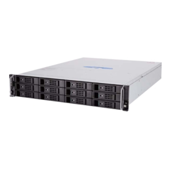
Storage System Features The Intel® Storage System SSR212CC is a 2U (rack space) disk drive enclosure, currently housing twelve low-profile (1-in high), 3.5-in form factor SATA disk drives. Figure 1 shows a front view of the Intel® Storage System SSR212CC while... -
Page 20: The Enclosure Core Product
D. Power Supply Cage E. Cooling Module The Enclosure Core Product The Intel® Storage System SSR212CC design concept is based on a sub-system together with a set of plug-in modules and (as supplied) comprises: • An enclosure chassis with backplane •... -
Page 21: Figure 3. Rear Isometric View
I. USB Port J. Video Port K. NIC2 Port (1 GB) L. NIC1 Port (1 GB) M. Serial Port N. PS2 Keyboard Port O. Reset Button P. Blanking Plate Q. Power Supply Module Indicator LED Intel® Storage System SSR212CC User Guide... -
Page 22: Enclosure Chassis
At the rear, the chassis assembly accommodates a power supply cage, a server board, and a PCI riser card assembly. A cover on the enclosure provides access to the cooling module and the server board sub- system. Intel® Storage System SSR212CC User Guide... -
Page 23: Server Board Sub-System
10/100/1000 LAN ports Power Supply Module The Intel® Storage System SSR212CC ships with one 500-W power supply module. A second 500-W power supply module can be ordered optionally as an accessory. Each power supply module comes with its own IEC inlet connector and failure indicator. -
Page 24: Multiple Power Supply Modules
A typical power supply module is shown in Figure 6. Multiple Power Supply Modules The Intel® Storage System SSR212CC can be operated with one or two power supply modules fitted in the power supply enclosure, providing dual-power sources for the system so that if one power supply module fails the other maintains the power supply and enclosure operation is not affected while the faulty unit is replaced. -
Page 25: Power Supply Output Cables
5 pascals (0.5-mm water gauge)]. The cooling system provides sufficient capacity to ensure that drive maximum temperatures are not exceeded at 35°C ambient with one fan failed at 7,000 ft. Intel® Storage System SSR212CC User Guide... -
Page 26: Drive Carrier
Each drive carrier incorporates a green Drive Status LED and an amber Drive Fault LED. Definition Drive Status LED Flashes green as drive operates Drive Fault LED Continuous amber light indicates a failure condition Intel® Storage System SSR212CC User Guide... -
Page 27: Blanking Plates
Warning: Operation of the storage system with ANY modules missing will disrupt the airflow and the drives will not receive sufficient cooling. Front Panel The front panel provides visibility access to three LEDs. TP01833 Figure 10. Front Panel A. Power LED B. Fault LED C. ID LED Intel® Storage System SSR212CC User Guide... -
Page 28: Spare Parts And Accessories
Warning: The Front Panel is an integral part of the chassis and is not field replaceable. Spare Parts and Accessories The following replaceable parts are available for the Intel® Storage System SSR212CC. Table 2. Spare Parts and Accessories Part Number... -
Page 29: Hardware Installations And Upgrades
This chapter provides instructions for removing, installing, and replacing storage system components in your Intel® Storage System SSR212CC. Caution: When connecting the Intel® Storage System SSR212CC to a power source, use either the power cords that shipped with the system, or match the power cord specifications listed under “Power Cord”... -
Page 30: Drive Bay Numbering Convention
(in the rack mount configuration). The Intel® Storage System SSR212CC subsystem is housed in a 4 x 3 enclosure, i.e., four drive bays wide by three bays high. The top bays are numbered 1 to 4 from left to right, as viewed from the front. -
Page 31: Installing The Enclosure In A Rack System
Hardware Installations and Upgrades Installing the Enclosure in a Rack System Warning: The Intel® Storage System SSR212CC enclosure with all its component parts installed is too heavy for a single person to easily install into a rack cabinet. The following... -
Page 32: Rack Mount Rail Kit
Please refer to the Rail Kit Install Guide: Intel Storage System SSR212MA/Intel® Storage System SSR212CC supplied with the rack mounting rail kit for assembly details. Removing or Installing the Enclosure Cover Warning: The enclosure cover must only be removed by a service personnel. Potential hazards include: •... -
Page 33: Figure 12. Unlatching Enclosure Cover
(see letter “A” in the following figure). Press in on the palm latch (see letter “B”) and slide the enclosure cover back (see letter “C”) until it stops (about 2 inches). TP01826 Figure 12. Unlatching Enclosure Cover Intel® Storage System SSR212CC User Guide... -
Page 34: Installing The Enclosure Cover
(see letter “B”). With a screwdriver, secure the enclosure cover to the chassis by tightening the lock a quarter turn until the close lock symbol aligns with the notch on the cover (see letter “C”). Intel® Storage System SSR212CC User Guide... -
Page 35: Removing Or Installing A Power Supply Module
AC input socket. Operation of the storage system with ANY modules missing will disrupt airflow and the drives will not receive sufficient cooling. It is ESSENTIAL that all apertures are filled before operating the system. Intel® Storage System SSR212CC User Guide... -
Page 36: Removing A Power Supply Module
Information”. 2. For non-redundant power supply systems only, power down the storage system. See the Intel® Storage System Software User’s Manual for instructions on powering down the system. 3. Remove the AC power cable from the failed power supply module. The top AC connector is for the left power supply. -
Page 37: Installing A Power Supply Module
1. Observe all safety and ESD precautions listed in Appendix D, “Safety Information”. 2. (For replacing a power supply module only) Remove the failed power supply module. For instructions, see “Removing a Power Supply Module” on page Intel® Storage System SSR212CC User Guide... -
Page 38: Figure 17. Removing Blanking Plate
(see letter “B”) until it clicks into place. TP01849 Figure 18. Inserting Power Supply Module 5. Plug in the AC power cable to the new power supply module. 6. On non-redundant power supply systems, power up the storage system. Intel® Storage System SSR212CC User Guide... -
Page 39: Connecting The Power Cord(S)
3. The Power On LED on each power supply module (see letter “B”) indicates whether AC mains power is present. Caution: The power connections must always be disconnected prior to removal of the power supply unit from the enclosure. TP01850 Figure 19. Connecting Power Cords Intel® Storage System SSR212CC User Guide... -
Page 40: Grounding Checks
Removing the PCI Riser Assembly Caution: Before performing any maintenance on the system, back up the data. Follow the instructions in the Intel® Storage System Software User Manual for shutting down the system. 1. Observe all safety and ESD precautions listed in Appendix D, “Safety... -
Page 41: Figure 20. Disconnecting First Sata Cable
8. Lift up on latch (see letter “A” in the following figure) and disconnect the main power (P1) cable from the server board (see letter “B”). TP02045 Figure 21. Disconnecting Main Power (P1) Cable from Server Board Intel® Storage System SSR212CC User Guide... -
Page 42: Figure 22. Disconnecting Remaining Two Sata Cables
(see letter “B”). Guide the SATA cables so that they clear the opening in the cross bar. Lay the PCI riser assembly on an anti-static surface. TP02043 Figure 23. Removing PCI Riser Assembly from Chassis Intel® Storage System SSR212CC User Guide... -
Page 43: Installing The Pci Riser Assembly
Hardware Installations and Upgrades 12. If you need to add or replace an Intel® RAID Controller SRCS28X, see “Removing and Installing an Intel® RAID Controller” on page 13. If you removed the PCI riser assembly as part of another procedure, continue with that procedure. -
Page 44: Figure 25. Connecting First Two Sata Cables
5. Connect the main P1 power cable to its connector on the server board (see letter “A” in the following figure). When properly seated, the latch on the top of the connector (see letter “B”) should lock the connector into position. TP02053 Figure 26. Connecting Main Power Cable Intel® Storage System SSR212CC User Guide... -
Page 45: Figure 27. Connecting Third Sata Cable To Server Board
“Installing the Processor Air Duct” on page 11. Install the enclosure cover. For instructions, see “Installing the Enclosure Cover” on page 12. Re-connect all peripheral devices and the AC power cable. Power up the storage system. Intel® Storage System SSR212CC User Guide... -
Page 46: Replacing A Pci Riser Connector Card
“Removing the PCI Riser Assembly” on page 6. Remove any installed Intel® RAID Controller SCRS28X cards. For instructions, see “Removing an Intel® RAID Controller” on page 7. Remove the four screws securing the old PCI riser connector card to the PCI riser assembly (see letter “A”... -
Page 47: Figure 29. Securing Pci Riser Connector Card To Pci Riser Assembly
PCI riser assembly with four screw (see letter “B”). TP02064 Figure 29. Securing PCI Riser Connector Card to PCI Riser Assembly 9. Install any Intel® RAID Controller SRCS28X cards. For instructions, see “Installing an Intel® RAID Controller” on page 10. -
Page 48: Removing And Installing An Intel ® Raid Controller
Caution: Before performing any maintenance on the system, back up the data. Follow the instructions in the operating system manual for shutting down the system. Caution: Refer to the support site at http://www.intel.com/support/motherboards/server/ssr212ma for the appropriate firmware version to use. -
Page 49: Figure 30. Disconnecting Sata Cables
Hardware Installations and Upgrades ® 7. Disconnect the SATA cables connected to the Intel RAID Controller being replaced. TP02065 Figure 30. Disconnecting SATA Cables 8. Disconnect the extended battery cable from the battery (see letter “A” in the following ®... -
Page 50: Figure 32. Removing Battery Backup Unit
Hardware Installations and Upgrades ® 9. Remove the three screws securing the battery backup unit to the Intel RAID Controller. Remove the battery backup unit. TP02338 Figure 32. Removing Battery Backup Unit ® 10. If removing the Intel RAID Controller as part of another procedure, continue with that procedure. -
Page 51: Installing An Intel ® Raid Controller
® ® 6. Unpack the Intel RAID Controller. Remove the Intel RAID Controller from the anti-static bag and inspect for damage. Contact Intel or your Intel support ® representative if the Intel RAID Controller appears damaged. ® 7. Configure the jumper settings on the Intel RAID Controller using the jumper definitions and locations in the documentation that shipped with the card. -
Page 52: Figure 34. Attaching Battery Backup Unit To Intel ® Raid Controller
Hardware Installations and Upgrades ® 9. Align and seat the battery backup unit in its connector on the Intel RAID Controller. ® Secure the battery backup unit to theIntel RAID Controller with three screws. TP02341 ® Figure 34. Attaching Battery Backup Unit to Intel RAID Controller Intel®... -
Page 53: Figure 35. Installing Intel ® Raid Controller
Hardware Installations and Upgrades ® 10. Align the Intel RAID Controller with the PCI-X slot on the PCI riser connector. ® Press down gently but firmly to properly seat the Intel RAID Controller in the slot. TP02342 ® Figure 35. Installing Intel RAID Controller 11. -
Page 54: Figure 37. Attach Sata Cables
13. Re-install the PCI riser assembly into the chassis. For instructions, see “Installing the PCI Riser Assembly” on page 14. Install the enclosure cover. For instructions, see “Installing the Enclosure Cover” on page 15. Re-connect all peripheral devices and the AC power cable. Intel® Storage System SSR212CC User Guide... -
Page 55: Replacing The Battery For An Intel ® Raid Controller
5. Turn off all peripheral devices connected to the storage system. Turn off the storage system. 6. Disconnect the AC power cord(s). 7. Remove the enclosure cover. For instructions, see “Removing the Enclosure Cover” on page Intel® Storage System SSR212CC User Guide... -
Page 56: Figure 40. Removing Battery Holder From Pci Riser Assembly
PCI riser assembly. TP02331 Figure 40. Removing Battery Holder from PCI Riser Assembly 10. Remove the two screws securing the old battery to the battery holder. TP02332 Figure 41. Removing Old Battery from Battery Holder Intel® Storage System SSR212CC User Guide... -
Page 57: Figure 42. Securing New Battery To Battery Holder
Hardware Installations and Upgrades 11. Secure the new battery to the battery holder with two screws. TP02334 Figure 42. Securing New Battery to Battery Holder Intel® Storage System SSR212CC User Guide... -
Page 58: Figure 43. Re-Attaching Battery Holder To Pci Riser Assembly
Figure 43. Re-attaching Battery Holder to PCI Riser Assembly ® 13. Remove the Intel RAID Controller with the bad battery from the PCI Riser Assembly. For instructions, see “Removing an Intel® RAID Controller” on page Intel® Storage System SSR212CC User Guide... -
Page 59: Figure 44. Detaching Bad Battery Backup Unit From Intel ® Raid Controller
Hardware Installations and Upgrades 14. Remove the three screws on the bottom side of the Intel® RAID Controller SRCS28X to detach the bad battery backup unit from the card. TP02338 ® Figure 44. Detaching Bad Battery Backup Unit from Intel RAID Controller 15. -
Page 60: Figure 46. Connecting Battery Cable To New Battery Backup Unit
TP02340 Figure 46. Connecting Battery Cable to New Battery Backup Unit ® 17. Secure the new backup battery unit to the Intel RAID Controller with three screws. TP02341 ®... -
Page 61: Installing A Pci Card
6. Unlatch the two levers (see letter “A” in the following figure) on the PCI riser assembly and lift the assembly out of the chassis (see letter “B”). TP02043 Figure 48. Removing PCI Riser Assembly from Chassis Intel® Storage System SSR212CC User Guide... -
Page 62: Figure 49. Removing Pci Slot Filler
7. Lay the PCI riser assembly upside down across the corner of the chassis. Take care not to unnecessarily pinch the SATA cables. Remove the PCI slot filler. AF000563 Figure 49. Removing PCI Slot Filler Intel® Storage System SSR212CC User Guide... -
Page 63: Figure 50. Installing Pci Card Into Pci Riser Assembly
Press the PCI card firmly into the connector to seat it properly into the PCI slot. Secure the PCI card to the PCI riser assembly with the screw that was removed in the previous step. AF000564 Figure 50. Installing PCI Card into PCI Riser Assembly Intel® Storage System SSR212CC User Guide... -
Page 64: Figure 51. Installing Pci Riser Assembly Into Chassis
“Installing the Processor Air Duct” on page 11. Re-install the enclosure cover. For instructions, see “Installing the Enclosure Cover” on page 12. Re-connect all peripheral devices and the AC power cable. Power up the storage system. Intel® Storage System SSR212CC User Guide... -
Page 65: Hot Swap Replacing, Removing Or Installing The Cooling Module
Press in on the palm latch (see letter “B”), and slide the enclosure cover back (see letter “C”) until it stops (about 2 inches), revealing the mounting brackets for the cooling module. TP01851 Figure 52. Accessing the Cooling Module Intel® Storage System SSR212CC User Guide... -
Page 66: Figure 53. Opening Cooling Module Latches
Caution: The cooling module must be replaced within 30 seconds to ensure the system does not overheat and shut down. TP01852 Figure 53. Opening Cooling Module Latches TP01780 Figure 54. Cooling Module with Latches in Open Position Intel® Storage System SSR212CC User Guide... -
Page 67: Figure 55. Unlatching Cooling Module From Chassis
Figure 55. Unlatching Cooling Module from Chassis 5. With the two latches in the open position, slide the old cooling module out of the enclosure. TP01780 TP01858 Figure 56. Removing Cooling Module from Chassis Intel® Storage System SSR212CC User Guide... -
Page 68: Figure 57. Installing The Cooling Module
Figure 57. Installing the Cooling Module 7. Cam the replacement (new) cooling module home by manually closing the latches. A click should be heard as the latches engage. TP01861 Figure 58. Latching Cooling Module into Chassis Intel® Storage System SSR212CC User Guide... -
Page 69: Removing The Cooling Module
1. Observe all safety and ESD precautions listed in Appendix D, “Safety Information”. 2. Turn off all peripheral devices connected to the storage system. Turn off the storage system. 3. Disconnect the AC power cord(s). Intel® Storage System SSR212CC User Guide... -
Page 70: Figure 60. Accessing The Cooling Module
Press in on the palm latch (see letter “B”), and slide the enclosure cover back (see letter “C”) until it stops (about 2 inches), revealing the mounting brackets for the cooling module. TP01851 Figure 60. Accessing the Cooling Module Intel® Storage System SSR212CC User Guide... -
Page 71: Figure 61. Unlatching Cooling Module
5. Rotate the two latches on the old cooling module to the open position. TP01860 Figure 61. Unlatching Cooling Module 6. With the two latches in the open position, slide the old cooling module out of the enclosure. TP01780 TP01858 Figure 62. Removing Cooling Module Intel® Storage System SSR212CC User Guide... -
Page 72: Installing The Cooling Module
Press in on the palm latch (see letter “B”), and slide the enclosure cover back (see letter “C”) until it stops (about 2 inches), revealing the mounting brackets for the cooling module. TP01851 Figure 63. Accessing the Cooling Module Intel® Storage System SSR212CC User Guide... -
Page 73: Figure 64. Opening Cooling Module Latches
3. Position the cooling module latches in the open position (see letter “A” in the following figure) on the cooling module. TP01852 Figure 64. Opening Cooling Module Latches TP01780 Figure 65. Cooling Module with Latches in Open Position Intel® Storage System SSR212CC User Guide... -
Page 74: Figure 66. Inserting Cooling Module Into Chassis
Figure 66. Inserting Cooling Module into Chassis 5. Cam the module home by manually closing the latches. A click should be heard as the latches engage. TP01861 Figure 67. Closing Latches on Cooling Module Intel® Storage System SSR212CC User Guide... -
Page 75: Replacing The Fan Interposer Board
3. Disconnect the AC power cord(s). 4. Remove the enclosure cover. For instructions, see “Removing the Enclosure Cover” on page 5. Remove the cooling module. For instructions, see “Removing the Cooling Module” on page Intel® Storage System SSR212CC User Guide... -
Page 76: Figure 68. Disconnecting Ipmb Cable From Fan Interposer Board
Hardware Installations and Upgrades 6. Disconnect the IPMB cable from the old fan interposer board (see letter “A” in the following figure). TP01868 Figure 68. Disconnecting IPMB Cable from Fan Interposer Board Intel® Storage System SSR212CC User Guide... -
Page 77: Figure 69. Removing Fan Interposer Board From Chassis
Disconnect the old fan interposer board (see letter “B”) from its connector on the backplane. Caution: Do not operate your storage system without a functioning fan interposer board installed in the system. TP02007 Figure 69. Removing Fan Interposer Board from Chassis Intel® Storage System SSR212CC User Guide... -
Page 78: Figure 70. Securing Fan Interposer Board To Chassis
8. Connect the new fan interposer board to its connector on the backplane (see letter “A” in the following figure). Secure the fan interposer board to the chassis with three screws (see letter “B”). TP02009 Figure 70. Securing Fan Interposer Board to Chassis Intel® Storage System SSR212CC User Guide... -
Page 79: Figure 71. Connecting Ipmb Cable To Fan Interposer Board
“Installing the Cooling Module” on page 11. Install the enclosure cover. For instructions, see “Installing the Enclosure Cover” on page 12. Re-connect all peripheral devices and the AC power cable. Power up the storage system. Intel® Storage System SSR212CC User Guide... -
Page 80: Removing Or Installing A Drive Carrier
Important: Before you begin installation you should become familiar with the configuration requirements of your Intel® Storage System SSR212CC. Refer to “Planning Your Installation” on page 11 for information on your overall system configurations. -
Page 81: Installing A Drive Carrier
Caution: An empty drive carrier MUST be fitted in ALL unused drive bays.There will be inadequate drive cooling if any drive bays are left open. 1. Observe all safety and ESD precautions listed in Appendix D, “Safety Information” Intel® Storage System SSR212CC User Guide... -
Page 82: Figure 74. Installing Drive Carrier Into Drive Bay
Important: Ensure that the carrier is orientated so that the drive is uppermost and the handle opens from the left. TP01832 Figure 74. Installing Drive Carrier into Drive Bay Intel® Storage System SSR212CC User Guide... -
Page 83: Removing Or Installing A Hard Drive Into A Drive Carrier
5. For instructions on re-installing the drive carrier into the drive bay, see “Installing a Drive Carrier” on page Intel® Storage System SSR212CC User Guide... -
Page 84: Installing A Hard Drive Into A Drive Carrier
(see letter “B”). TP01829 Figure 76. Installing Hard Drive in Drive Carrier 5. For instructions on re-installing the drive carrier into the drive bay, see “Installing a Drive Carrier” on page Intel® Storage System SSR212CC User Guide... -
Page 85: Replacing An Intel ® Server Board Se7520Jr2
“Removing the PCI Riser Assembly” on page 8. Remove the heat sink and processor. For instructions, see “Removing the Processor” on page 9. Remove the memory DIMMs. For instructions, see “Removing DIMMs” on page Intel® Storage System SSR212CC User Guide... -
Page 86: Figure 77. Disconnecting Cables From Server Board
(see letter “C”). Disconnect the reset (see letter “D”) and power switch (see letter “E”) cables. TP02010 Figure 77. Disconnecting Cables from Server Board 11. Remove the IMM Pro module. For instructions, see “Removing the IMM Pro Module” on page Intel® Storage System SSR212CC User Guide... -
Page 87: Figure 78. Removing Server Board From Chassis
Hardware Installations and Upgrades 12. Remove the seven screws securing the server board to the chassis. Remove server board from chassis and store in an anti-static bag. TP02012 Figure 78. Removing Server Board from Chassis Intel® Storage System SSR212CC User Guide... -
Page 88: Installing A Server Board
TP02012 Figure 79. Installing Server Board in Chassis 2. Install the processor and heatsink. For instructions, see “Installing the Processor” on page 3. Install the memory DIMMs. For instructions, see “Installing DIMMs” on page Intel® Storage System SSR212CC User Guide... -
Page 89: Figure 80. Connecting Cables To Server Board
8. Install the cooling module. For instructions, see “Installing the Cooling Module” on page 9. Install the enclosure cover. For instructions, see “Installing the Enclosure Cover” on page 10. Re-connect all peripheral devices and the AC power cable. Intel® Storage System SSR212CC User Guide... -
Page 90: Removing Or Installing The Processor Air Duct
5. Lift the processor air duct from its location over the processor socket(s). TP01856 Figure 81. Removing Processor Air Duct 6. If removing a processor air duct as part of another procedure, continue with that procedure. Intel® Storage System SSR212CC User Guide... -
Page 91: Installing The Processor Air Duct
Caution: Before performing any maintenance on the system, back up the data. Follow the instructions in the operating system manual for shutting down the system. Warning: Do not operate the Intel® Storage System SSR212CC without the presence of a processor air duct. -
Page 92: Removing Or Installing The Processor
Hardware Installations and Upgrades Removing or Installing the Processor The Intel® Storage System SSR212CC does not support a two-processor configuration. ® ® The current system only supports a single low-voltage Intel Xeon 2.8 GHz processer with an 800-MHz system bus and 1-MB L2 cache. -
Page 93: Figure 83. Removing Heatsink
If it does not pull up easily, twist the heatsink again. Caution: Do not force the heatsink from the processor. Doing so could damage the processor. TP01775 Figure 83. Removing Heatsink 7. Lift the processor lever. TP01776 Figure 84. Opening Socket Lever Intel® Storage System SSR212CC User Guide... -
Page 94: Installing The Processor
3. Disconnect the AC power cord(s). 4. Remove the enclosure cover. For instructions, see “Removing the Enclosure Cover” on page 5. Remove the processor air duct. For instructions, see “Removing the Processor Air Duct” on page Intel® Storage System SSR212CC User Guide... -
Page 95: Figure 86. Opening Socket Lever
7. Align the pins of the processor with the socket, and insert the processor into the socket. Note: Make sure the alignment triangle mark and the alignment triangle cut-out align correctly. TP00764 Figure 87. Inserting Processor Intel® Storage System SSR212CC User Guide... -
Page 96: Figure 88. Closing Socket Lever
Loosely screw in the captive screws on the heatsink corners in a diagonal manner. Do not fully tighten one screw before tightening another. Gradually and equally tighten each captive screw until each is firmly tightened. TP00774 Figure 89. Installing the Heatsink Intel® Storage System SSR212CC User Guide... -
Page 97: Replacing A Chassis (Fxcchassis)
6. Remove the processor air duct. For instructions, see “Removing the Processor Air Duct” on page 7. Remove the PCI riser assembly. For instructions, see “Removing the PCI Riser Assembly” on page Intel® Storage System SSR212CC User Guide... -
Page 98: Figure 90. Disconnecting Cables From Server Board
Disconnect the IPMB cable (see letter “B”). Disconnect the P3 power supply signal cable (see letter “C”). Disconnect the reset (see letter “D”) and power switch (see letter “E”) cables. AF00571 Figure 90. Disconnecting Cables from Server Board Intel® Storage System SSR212CC User Guide... -
Page 99: Figure 91. Installing Server Board In Chassis
10. Ensure that all the drive carriers have been labeled according to the following numbering order. TP01831 Figure 92. Drive Bay Numbering Order 11. Remove all drive carriers. For instructions, see “Removing a Drive Carrier” on page Intel® Storage System SSR212CC User Guide... -
Page 100: Figure 93. Installing Server Board In Chassis
Note: The following steps are performed on the replacement chassis. 12. Install the server board by aligning the screw holes in the server board with the standoffs in the new chassis. TP02012 Figure 93. Installing Server Board in Chassis Intel® Storage System SSR212CC User Guide... -
Page 101: Figure 94. Connecting Cables To Server Board
Connect the IPMB cable (see letter “B”). Connect the P3 power supply signal cable (see letter “C”). Connect the reset (see letter “D”) and power switch (see letter “E”) cables. AF00571 Figure 94. Connecting Cables to Server Board Intel® Storage System SSR212CC User Guide... -
Page 102: Figure 95. Connecting P4 Power Supply Cable To Backplane
63. Ensure that all drive carriers are installed in the proper order. TP01831 Figure 96. Drive Bay Numbering Order 20. Re-connect all peripheral devices and the AC power cable. Power up the storage system. Intel® Storage System SSR212CC User Guide... -
Page 103: Replacing The Server Board Battery
3. Disconnect the AC power cord(s). 4. Remove the enclosure cover. For instructions, see “Removing the Enclosure Cover” on page 5. Remove the processor air duct. For instructions, see “Removing the Processor Air Duct” on page Intel® Storage System SSR212CC User Guide... -
Page 104: Figure 97. Removing Pci Riser Assembly From Chassis
Place a support underneath the PCI riser assembly, next to the chassis and workbench, to minimize the stress on the cables (see letter “D”). TP00879 Figure 97. Removing PCI Riser Assembly from Chassis Intel® Storage System SSR212CC User Guide... -
Page 105: Figure 98. Removing Server Board Battery
Figure 98. Removing Server Board Battery 8. Dispose of the battery according to local ordinance. 9. Remove the new lithium battery from its package, and, being careful to observe the correct polarity, insert it in the battery socket. Intel® Storage System SSR212CC User Guide... -
Page 106: Figure 99. Installing Pci Riser Assembly Into Chassis
“Installing the Processor Air Duct” on page 12. Install the enclosure cover. For instructions, see “Installing the Enclosure Cover” on page 13. Re-connect all peripheral devices and the AC power cable. Power up the storage system. Intel® Storage System SSR212CC User Guide... -
Page 107: Removing Or Installing Memory
Figure 100. DIMM Identification Memory Requirements The Intel® Server Board SE7520JR2 provides six DIMM sockets across two channels: Channel A and Channel B. Channel A consists of DIMM sockets 1A, 2A, and 3A. Channel B consists of DIMM sockets 1B, 2B, and 3B. Refer to the Tested Memory List at http://www.intel.com/support/motherboards/server/ssr212cc/... -
Page 108: Table 4. Dimm Module Memory Capacity Support
Memory Sparing and Mirroring The Intel® E7520 chipset includes hardware that supports memory mirroring and memory on-line sparing. Both memory mirroring and memory on-line sparing provide a way to prevent data loss in case of a DIMM failure. -
Page 109: Removing Dimms
3. Disconnect the AC power cord(s). 4. Remove the enclosure cover. For instructions, see “Removing the Enclosure Cover” on page 5. Remove the processor air duct. For instructions, see “Removing the Processor Air Duct” on page Intel® Storage System SSR212CC User Guide... -
Page 110: Figure 101. Removing Memory
“Installing the Processor Air Duct” on page 10. Install the enclosure cover. For instructions, see “Installing the Enclosure Cover” on page 11. Re-connect all peripheral devices and the AC power cable. Power up the storage system. Intel® Storage System SSR212CC User Guide... -
Page 111: Installing Dimms
Once the DIMM is inserted, push down on the top edge of the DIMM until the retaining clips snap into place. Make sure the clips are latched firmly in place. DIMM 2A DIMM 2B DIMM 3B DIMM 1A DIMM 3A DIMM 1B TP00761 Figure 102. Installing Memory Intel® Storage System SSR212CC User Guide... -
Page 112: Removing Or Installing The Intel® Management Module Professional (Imm Pro) Module
This may require setting up the module in an external system (with a CD-ROM or floppy drive) and updating with the appropriate firmware version. Refer to the Intel® Storage System SSR212CC Tested Hardware and Operating System List for the tested firmware version. Refer to the support site at http://www.intel.com/support/ motherboards/server/ism for the appropriate firmware and documentation to download. -
Page 113: Figure 103. Removing Pci Riser Assembly From Chassis
Place a support underneath the PCI riser assembly, next to the chassis and workbench, to minimize the stress on the cables (see letter “D”). TP00879 Figure 103. Removing PCI Riser Assembly from Chassis Intel® Storage System SSR212CC User Guide... -
Page 114: Figure 104. Removing Imm Pro Module From Server Board
TP02011 Figure 104. Removing IMM Pro Module from Server Board 7. If removing the IMM Pro module as part of another procedure, continue with that procedure. Intel® Storage System SSR212CC User Guide... -
Page 115: Figure 105. Installing Pci Riser Assembly Into Chassis
Figure 105. Installing PCI Riser Assembly into Chassis 9. Install the enclosure cover. For instructions, see “Installing the Enclosure Cover” on page 10. Re-connect all peripheral devices and the AC power cable. Power up the storage system. Intel® Storage System SSR212CC User Guide... -
Page 116: Installing The Imm Pro Module
Place a support underneath the PCI riser assembly, next to the chassis and workbench, to minimize the stress on the cables (see letter “D”). Intel® Storage System SSR212CC User Guide... -
Page 117: Figure 106. Removing Pci Riser Assembly From Chassis
TP00879 Figure 106. Removing PCI Riser Assembly from Chassis 6. If not already present, attach the nylon stand-off to the IMM Pro module. TP02344 Figure 107. Securing IMM Pro Module Stand-off to Server Board Intel® Storage System SSR212CC User Guide... -
Page 118: Figure 108. Installing Imm Pro Module To Server Board
Pro module until the module seats itself in the connector (see letter “B”) on the server board. TP01867 Figure 108. Installing IMM Pro Module to Server Board 8. If installing the IMM Pro module as part of another procedure, continue with that procedure. Intel® Storage System SSR212CC User Guide... -
Page 119: Figure 109. Installing Pci Riser Assembly Into Chassis
Figure 109. Installing PCI Riser Assembly into Chassis 10. Install the enclosure cover. For instructions, see “Installing the Enclosure Cover” on page 11. Re-connect all peripheral devices and the AC power cable. Power up the storage system. Intel® Storage System SSR212CC User Guide... - Page 120 Hardware Installations and Upgrades Intel® Storage System SSR212CC User Guide...
-
Page 121: Operation
LED. Table 5. Power Supply Module LED Indicators Power Supply Condition Power Supply LED No AC power to all power supply modules No AC power to this power supply module only Amber Intel® Storage System SSR212CC User Guide... -
Page 122: Front Panel Leds
The blue system identification LED is used to help identify a system for servicing. This is especially useful when the system is installed in a high-density rack or cabinet that is populated with several similar systems. Intel® Storage System SSR212CC User Guide... -
Page 123: Rear Panel Buttons
In the event of a system failure or hang condition that prevents you from powering ® down the system via the Intel Storage System Console, do the following: Hold down the Power button for approximately 3 seconds Remove AC mains at the power source. Intel® Storage System SSR212CC User Guide... - Page 124 Operation Intel® Storage System SSR212CC User Guide...
-
Page 125: Troubleshooting And Problem Solving
Troubleshooting and Problem Solving Overview The Intel® Storage System SSR212CC enclosure includes an enclosure services processor and associated monitoring and control logic to enable it to diagnose problems within the enclosure’s power, cooling and drive systems. The sensors for power and cooling conditions are housed within the power supply and cooling modules. -
Page 126: Front Panel
Troubleshooting The following sections describe common problems, with possible solutions, which can ® occur with your Intel® Storage System SSR212CC. Refer to the Intel Server Board SE7520JR2 User Guide for additional troubleshooting information on the server board. For details on how to remove and replace a module, see Chapter 2, “Hardware... -
Page 127: Power Supply Module Faults
Thermal Control The Intel® Storage System SSR212CC enclosure uses extensive thermal monitoring and takes a number of actions to ensure component temperatures are kept low and also to minimize acoustic noise. Airflow is from front to rear of the enclosure. -
Page 128: Thermal Alarm
5. If possible shutdown the enclosure and investigate the problem before continuing. Thermal Shutdown Important: An enclosure will shut down when a critical temperature threshold is exceeded in order to prevent permanent damage to the disk drives. Intel® Storage System SSR212CC User Guide... -
Page 129: Drive Carrier Module Faults
Ensure that you have obtained a replacement module of the same type before removing any faulty module. Warning: If the Intel® Storage System SSR212CC sub-system is powered up and you remove any module, replace it immediately. If the subsystem is used with modules or module blanks missing for more than a few minutes, the storage system can overheat, causing power failure and data loss. - Page 130 Troubleshooting and Problem Solving Intel® Storage System SSR212CC User Guide...
-
Page 131: Technical Specifications
Full Range power supply unit Frequency 50/60 Hz Inrush Current 50A @ 260VAC Power Factor Corrections 95%@110V full load Harmonics Meets EN61000-3-2 Output Rails Dimensions 84 mm high x 101 mm wide x 300 mm long Intel® Storage System SSR212CC User Guide... -
Page 132: Power Supply Safety And Emc Compliance
NEMA 5-15P grounding-type attachment plug rated 120V 10A IEC 320 C14, 250V, 10A. Socket IEC 320, C-13, 250V, 10A. Europe and Others General requirements: Cord type Harmonized, H05-VVF-3G1.0 Socket IEC 320, C-13, 250V, 10A. Intel® Storage System SSR212CC User Guide... -
Page 133: Cooling Module
-305 to 12,192 m (-1000 to 40,000 ft) Shock, Operational Vertical axis 5g peak 1/2 sine, 10ms Shock, Non-operational 20g 10ms 1/2 sine (test with drives) 30g 10ms 1/2 sine (test without drives) Vibration, Operational 0.2grms 5-500 Hz Random Intel® Storage System SSR212CC User Guide... -
Page 134: Drive Carrier Specification
EN55022 (CISPR-A), FCC A Drive Carrier Specification Please contact your supplier for details of approved drives. Important: Operating the Intel® Storage System SSR212CC with non-approved drives may invalidate the warranty. Module Dimensions Height 26.6 mm Width 106.5 mm Depth 220.2 mm Weight 0.8 kg (1.0”... -
Page 135: A Intel ® Server Board Se7520Jr2 Bios Settings
4. Make modifications to the BIOS as stipulated in following table. 5. When done, select <Save Custom Defaults> from the Exit menu. 6. Select <SAVE Changes and Exit>. Table 10. Intel® Server Board SE7520JR2 BIOS Settings BIOS Setup Option Feature... - Page 136 ® Intel Server Board SE7520JR2 BIOS Settings Intel® Storage System SSR212CC User Guide...
-
Page 137: Braid Levels
RAID 0 usually denotes two or more drives. RAID 0 ABCDEF Available Capacity RAID Adapter N=# disks C = Disk Capacity Available Capacity = N*C Data Striping RAID 0 Figure 111. RAID 0 - Data Striping Intel® Storage System SSR212CC User Guide... -
Page 138: Raid 1 - Disk Mirroring / Disk Duplexing
RAID 5 ABCDEF Available Capacity RAID Adapter N=# disks C = Disk Capacity Available Capacity = Data Striping & (N*C)(N-1) /N Striped Parity RAID 5 Figure 113. RAID 5 - Data Striping with Striped Parity Intel® Storage System SSR212CC User Guide... -
Page 139: Raid 10 - Combination Of Raid 1 And Raid 0
Available Capacity RAID Adapter N=# disks C = Disk Capacity Available Capacity = (N*C) /2 Disk Mirror & Data Striping RAID 10 Figure 114. RAID 10 - Combination of RAID 1 and RAID 0 Intel® Storage System SSR212CC User Guide... -
Page 140: Raid 50 - Combination Of Raid 5 And Raid 0
RAID Adapter N=# disks C = Disk Capacity Available Capacity = (N*C)(N-1) /N P1(B+D) P(F+H) P(J+L) RAID 5 & Data Striping RAID 50 Figure 115. RAID 50 - Combination of RAID 5 and RAID 0 Intel® Storage System SSR212CC User Guide... -
Page 141: C Upgrading Component Firmware
Upgrading Component Firmware or the Server Board BIOS ® ® If replacing an Intel Server Board SE7520JR2 or Intel RAID Controller, refer to the support site at http://www.intel.com/support/motherboards/server/ssr212cc downloading the appropriate firmware or BIOS. Intel® Storage System SSR212CC User Guide... - Page 142 Upgrading Component Firmware Intel® Storage System SSR212CC User Guide...
-
Page 143: D Safety Information
To reduce the risk of bodily injury, electrical shock, fire, and equipment damage, read this document and observe all warnings and precautions in ® this guide before installing or maintaining your Intel server product. In the event of a conflict between the information in this document and information provided with the product or on the website for a particular product, the product documentation takes precedence. -
Page 144: Intended Application Uses
AC power, 5V standby power is active whenever the system is plugged in. To remove power from system, you must unplug the AC power cord from the wall outlet. Your system may use more than one AC power cord. Make sure all AC power cords are Intel® Storage System SSR212CC User Guide... -
Page 145: System Access Warnings
Turn off all peripheral devices connected to this product. • Turn off the system by pressing the power button to off. • Disconnect the AC power by unplugging all AC power cords from the system or wall outlet. Intel® Storage System SSR212CC User Guide... -
Page 146: Rack Mount Warnings
Always handle boards carefully. They can be extremely sensitive to ESD. Hold boards only by their edges. After removing a board from its protective wrapper or from the server, place the board component side up on a grounded, static free surface. Use a Intel® Storage System SSR212CC User Guide... -
Page 147: Other Hazards
Caution: To avoid risk of radiation exposure and/or personal injury: • Do not open the enclosure of any laser peripheral or device • Laser peripherals or devices have are not user serviceable • Return to manufacturer for servicing Intel® Storage System SSR212CC User Guide... -
Page 148: Deutsch
Safety Information Deutsch Sicherheitshinweise für den Server Das vorliegende Dokument bezieht sich auf Intel® Serverplatinen, Intel® Servergehäuse (Standfuß und Rack) sowie installierte Peripheriegeräte. Es enthält Warnungen und Vorsichtsmaßnahmen zur Vermeidung von Gefahren durch Verletzung, Stromschlag, Feuer und Beschädigungen von Geräten. Lesen Sie diese Dokument daher sorgfältig, bevor Sie Ihr Intel®... -
Page 149: Zielbenutzer Der Anwendung
• Verwenden Sie mechanische oder andere geeignete Hilfsmittel zum Transportieren oder Anheben von Geräten. • Entfernen Sie alle Komponenten, die sich leicht abnehmen lassen, um das Gewicht zu reduzieren und die Handhabung zu erleichtern. Intel® Storage System SSR212CC User Guide... - Page 150 Typ entspricht. Jedes Netzteil im System muß über ein eigenes Netzkabel angeschlossen werden. Einige Netzteile von Intel Servern verwenden Nullleitersicherungen. Vorsicht ist geboten im Umgang mit Netzteilen, welche Nullleitersicherungen verwenden, um das Risiko eines elektrischen Schlages zu vermeiden Das Netzteil in diesem Produkt enthält keine Teile, die vom Benutzer gewartet werden...
-
Page 151: Warnhinweise Für Den Systemzugang
Einbauen von Hot-Plug-Komponenten sorgfältig vor, um nicht mit heißen Komponenten in Berührung zu kommen. Vorsicht: Berühren Sie nicht die rotierenden Lüfterflügel, um Verletzungen zu vermeiden. Falls Ihr System mit eine Lüfterabdeckung besitzt, darf es nicht ohne diese Abdeckung betrieben werden. Intel® Storage System SSR212CC User Guide... -
Page 152: Elektrostatische Entladungen (Esd)
Ausbau aus dem Server mit der Bauelementseite nach oben auf eine geerdete, statisch entladene Unterlage.Verwenden Sie dazu, sofern verfügbar, eine leitfahige Schaumstoffunterlage, aber niche die Schutzhülle der Platine. Ziehen Sie die Platine nicht über eine Fläche. Intel® Storage System SSR212CC User Guide... -
Page 153: Andere Gefahren
Vorsicht: Beachten Sie zur Vermeidung von Strahlung und Verletzungen die folgenden Hinweise: • Öffnen Sie keinesfalls das Gehäuse von Laser-Peripheriegeräten oder Laser- Komponenten. • Laser-Peripheriegeräte oder -Komponenten besitzen keine für den Benutzer wartungsbedürftigen Teile. • Schicken Sie das Gerät für Wartungsarbeiten an den Hersteller zurück. Intel® Storage System SSR212CC User Guide... -
Page 154: Français
Français Consignes de sécurité sur le serveur Ce document s’applique aux cartes serveur Intel®, au châssis de serveur Intel® (sur pieds et sur rack) et aux périphériques installés. Pour réduire les risques de dommages corporels, d’électrocution, d’incendie et de dommages matériels, lisez ce document et respectez tous les avertissements et précautions mentionnés dans ce guide avant... -
Page 155: Domaines D'utilisation Prévus
• Utilisez l’assistance mécanique ou toute autre assistance appropriée lorsque vous déplacez et soulevez le matériel. • Pour réduire le poids en vue de faciliter la manipulation, retirez tout composant amovible. Intel® Storage System SSR212CC User Guide... - Page 156 Vous devez les débrancher avant d’ouvrir le châssis, d’ajouter ou de supprimer un composant non connectable à chaud. Les alimentations de certains serveurs Intel sont munies de doubles fusibles pôle/neutre: veuillez observer les précautions d'usage afin d'éviter tout risque d'eléctrocution.
- Page 157 Attention: Pour éviter de vous blesser, ne touchez pas les pales de ventilateur en mouvement. Si votre système est fourni avec une protection sur le ventilateur, ne mettez pas le système en route sans la protection en place. Intel® Storage System SSR212CC User Guide...
-
Page 158: Décharges Électrostatiques (Esd)
à la terre, exempte de charge statique, composants orientés vers le haut. Utilisez si possible un tapi de mousse conducteru, mais pas l’emballage de la carte. Veillez à ce que la carte ne glisse sur aucune surface. Intel® Storage System SSR212CC User Guide... -
Page 159: Autres Risques
Attention: Pour éviter tout risque d’exposition aux rayonnements et/ou de dommage personnel: • N’ouvrez pas l’enceinte d’un périphérique laser. • Les périphériques laser ne sont pas réparables par l’utilisateur. • Retournez-les au fabricant en cas de problème. Intel® Storage System SSR212CC User Guide... -
Page 160: Español
Safety Information Español Información de seguridad del servidor ® Este documento se aplica a las tarjetas de servidor de Intel , las carcasas de servidor de ® Intel (montaje en bastidor y en pedestal) y los dispositivos periféricos. Para reducir el riesgo de daños corporales, descargas eléctricas, fuego y en el equipo, lea este documento... -
Page 161: Aplicaciones Y Usos Previstos
Utilice medios mecánicos u otros que sean adecuados al trasladar o levantar el equipo. • Para que el peso sea menor para manipularlo con más facilidad, extraiga los componentes que sean de fácil extracción. Intel® Storage System SSR212CC User Guide... - Page 162 CA estén desenchufado antes de abrir la carcasa, agregar o extraer cualquier componente que no es de conexión en funcionamiento. Algunas fuentes de alimentación de electricidad de los servidores de Intel utilizan el polo neutral del fuselaje. Para evitar riesgos de choques electricos use precauciónes al trabajar con las fuentes de alimentación que utilizan el polo neutral de fuselaje.
-
Page 163: Advertencias El Acceso Al Sistema
Precaución: Para evitar posibles daños, no toque las aspas en movimiento de los ventiladores. Si el sistema se le ha suministrado con una protección para el ventilador, asegúrese de que cuando esté funcionando el sistema la protección esté en su sitio. Intel® Storage System SSR212CC User Guide... -
Page 164: Descarga Electrostática (Esd)
Utilice una almohadilla de espuma conductora si dispone de ella, pero nunca el envoltorio de la tarjeta. No deslice la tarjeta sobre ninguna superficie. Intel® Storage System SSR212CC User Guide... - Page 165 Precaución: Para evitar el riesgo de la exposición a radiaciones o de daños personales: • No abra la caja de ningún periférico o dispositivo láser • Los periféricos o dispositivos láser no pueden ser reparados por el usuario • Haga que el fabricante los repare. Intel® Storage System SSR212CC User Guide...
- Page 166 认证和其他管理审批无效,并可能导致产品不符合销售地的产品法规。 安全警告与注意事项 为避免人身伤害与财产损失,安装本产品之前,请阅读以下所有安全指导和信息。 下面所列的安全符号可能在整个文档中使用并可能标注于产品和 / 或产品包装之上。 注意 表示如果无视此“? ? ? 项”? ? ? ? ? ? ? 轻微人身伤害或财产损失的危险。 警告 表示如果无视此“? ? ”? ? ? ? ? ? ? 严重人身伤害的危险。 表示如果无视所示信息,即存在潜在的危险。 表示如果不遵守安全指导,存在可导致严重伤害或死亡的电击危险。 表示灼热组件或表面。 表示请勿触摸风机叶片,否则可能致伤。 表示拔下所有交流电线,断开交流电源 Intel® Storage System SSR212CC User Guide...
- Page 167 通风良好,远离热源(包括直接日晒和散热器)。 • 远离振动源或物理震动。 • 与电气设备产生的强大电磁场隔离。 • 在易受闪电袭击的地区,我们建议将系统插入电涌抑制器并在闪电期间断开通信 线路与调制解调器之间的连接。 • 提供正确接地的墙壁插座。 • 提供足够的空间,以便拿取电源供应线,因为这是本产品的主要电源断开器。 设备操作规范 减少人身伤害或设备受损的危险: • 移举设备时遵守当地的职业健康与安全要求。 • 借助机械手段或其他合适的手段移举设备。 • 拆除一切易分离组件,以降低重量并方便操作。 电源与电气警告 注意事项 电源按钮(如待机电源标记所示)并不能完全关闭系统的交流电源,只要系统已接 通电源,就存在 5V 待机电源。要从系统切断电源,须从墙壁电源插座中拔下交流电线。您的系统可能 不止使用一根交流电线。请确保所有的交流电线都已拔下。打开机箱或增加或去除 任何热插拔组件之前,确保交流电线已拔下。 若非所需的确切类型,请勿尝试修改或使用交流电线。系统的每个电源供应设备都 需要一根单独的交流电线。 本产品的电源供应设备包含非用户维修部件。请勿打开电源供应设备。电源供应设 备包含非常危险的电压级、电流级和能量级。请与生产商联系维修事宜。 替换热插拔电源供应设备时,请先拔下需替换的电源供应设备上的电源线,再将其 从服务器上移除。 Intel® Storage System SSR212CC User Guide...
- Page 168 ⎯ 电源线的电气额定值须大于产品上标注的电流额定值。 ⎯ 电源线须拥有适合插座的安全接地插头或触点。 • 电源线为交流电源的主要断开设备。插座须靠近设备并可随时断开。 • 电源线须插入所提供的拥有合适接地的插座。 系统使用警告 注意事项 为避免人身伤害或财产损失,无论何时检查产品内部,以下安全指导都适用: • 关闭所有与本产品相连的外设。 • 按下电源按钮至关闭状态,关闭系统。 • 从系统或墙壁插座上拔下所有交流电线,断开交流电源。 • 断开与系统相连的所有线缆和通信线路。 • 卸除舱口盖时,保留所有螺钉及其他紧固件。完成产品内部检查之后,请 用螺钉或紧固件重新固定舱口盖。 • 请勿打开电源供应设备。电源供应设备内没有可维修部件。请与生产商联系 维修事宜. • 增加或替换任何非热插拔组件之前,请关闭服务器电源并断开所有电源线 。 • 替换热插拔电源供应设备时,请先拔下需替换的电源供应设备上的电源线 ,然后再从服务器上移除电源供应设备。 注意事项 如果服务器一直在运行,任何已安装的处理器和吸热设备都可能很热。除非要增加 或移除热插拔组件,否则请待系统冷却后再开盖。为避免在热插拔组件安装过程中 接触灼热组件,移除或安装热插拔组件时务须小心。 Intel® Storage System SSR212CC User Guide...
- Page 169 Safety Information 注意事项 为避免受伤,请勿触摸运转的风机叶片。如果系统的风机上配有防护装置,请勿卸 下风机防护装置运行系统。 机架固定件警告 设备的机架须固定在稳固的支座上,以防从中安装服务器或设备时倒塌。须按照机 架生产商提供的安装说明进行安装。 从下往上将设备安装在机架上,最重的设备安装在机架的最底层。 一次只从机架上安装一件设备。 您须负责安装整个机架装置的主要电源断开设备。此主要断开设备须随时可用,且 须标明为控制整个装置(而不仅限于服务器)的电源。 为避免潜在的电击危险,须对机架及其上所安装的每一件设备实行正确的安全接地 。 静电放电 (ESD) 注意事项 ESD 会损坏磁盘驱动器、主板及其他部件。我们建议您执行 ESD 工作站的所有步骤。如果没有 ESD 工作站,则采取一些静电放电保护措施,操作部件时,戴上与服务器上的机箱接地 或任何未喷漆金属表面连接的防静电腕带。 操作主板时始终保持小心。它们可能对 ESD 非常敏感。拿持主板时只接触边缘。从保护包装中或从服务器上取出主板后,请将 主板组件侧面朝上放置在无静电的接地表面上。请使用导电泡沫垫(若有),不要 使用主板包装。请勿将主板在任何表面上滑动。 Intel® Storage System SSR212CC User Guide...
- Page 170 Safety Information 其他危险 替换电池 注意事项 不正确替换电池可能导致爆炸危险。替换电池时,请只使用设备生产商推荐使用的 电池。 请按当地法规处置电池。 请勿对电池充电。 请勿拆卸、刺穿或以其他方式损坏电池。 冷却和气流 注意事项 按照说明小心布置线缆,尽量减少气流阻塞和冷却问题。 为保证适当的冷却和气流,运行系统时请确保机箱盖已安装。未安装机箱盖即运行 系统可能导致系统部件受损。安装机箱盖的步骤如下: 首先检查并确保系统内没有遗留的未固定工具或部件。 • 检查线缆、内插板和其他组件已正确安装。 • 按产品说明安装机箱盖。 • 激光外设或激光设备 注意事项 为避免幅射暴露和 / 或人身伤害: 请勿打开任何激光外设或激光设备的外壳 • 激光外设或激光设备为非用户维修设备 • 请与生产商联系维修事宜 Intel® Storage System SSR212CC User Guide...
-
Page 171: E Intel ® Server Issue Report Form
Intel Server Issue Report Form Note: An on-line / automatic submission version of this form is available at http:// support.intel.com/support/motherboards/server/ssr212cc/. For the fastest service, please submit your form via the Internet. Date Submitted: _______________________________________________________ Company Name: ______________________________________________________ Contact Name: ________________________________________________________... - Page 172 Peripheral Card or Peripheral Description Driver Revision IRQ # I/O Base Address NIC Driver I/O Base Peripheral Description Revision Address Revision Full-height Riser PCI Slot 1 PCI Slot 2 PCI Slot 3 Video On-board Video Add-in Video On-Board NIC1 On-Board NIC2 Intel® Storage System SSR212CC User Guide...
- Page 173 In the space below, provide a complete description of the steps used to reproduce the problem or a complete description of where the problem can be found. Please also include any details on troubleshooting already done. ____________________________________________________________________ ____________________________________________________________________ ____________________________________________________________________ ____________________________________________________________________ ____________________________________________________________________ ____________________________________________________________________ Intel® Storage System SSR212CC User Guide...
- Page 174 ® Intel Server Issue Report Form ____________________________________________________________________ ____________________________________________________________________ ____________________________________________________________________ ____________________________________________________________________ ____________________________________________________________________ ____________________________________________________________________ ____________________________________________________________________ ____________________________________________________________________ ____________________________________________________________________ ____________________________________________________________________ ____________________________________________________________________ ____________________________________________________________________ ____________________________________________________________________ ____________________________________________________________________ ____________________________________________________________________ Intel® Storage System SSR212CC User Guide...
-
Page 175: F Getting Help
Telephone All calls are billed US $25.00 per incident, levied in local currency at the applicable credit card exchange rate plus applicable taxes. (Intel reserves the right to change the pricing for telephone support at any time without notice). Before calling, fill out an “Intel®... -
Page 176: In Asia-Pacific Region
Chile Easter Island....Contact AT&T USA at 800 800 311. Once connected, dial 800 843 4481 Mainland and Juan .. Contact AT&T USA at 800 225 288. Once connected, dial 800 843 4481 Intel® Storage System SSR212CC User Guide... - Page 177 Panama..Contact AT&T USA at 00 800 001 0109. Once connected, dial 800 843 4481 Paraguay ... 001 916 377 0114 Peru ... 001 916 377 0114 Uruguay..001 916 377 0114 Venezuela... Contact AT&T USA at 0 800 2255 288. Once connected, dial 800 843 4481 Intel® Storage System SSR212CC User Guide...
- Page 178 Getting Help Intel® Storage System SSR212CC User Guide...
-
Page 179: G Regulatory And Compliance Information
(or higher) speed as the microprocessor used on this server board. The final configuration of your end system product may require additional EMC compliance testing. For more information, please contact your local Intel representative. -
Page 180: Product Emc Compliance - Class A Compliance
This product has been tested and verified to comply with the following electromagnetic compatibility (EMC) regulations when installed in a compatible Intel® host system. For information on compatible host system(s) refer to Intel's Server Builder Web site or contact your local Intel representative. -
Page 181: Product Regulatory Compliance Markings
Table 11. Product Regulatory Compliance Markings Regulatory Country Marking Compliance cULus Listing Marks USA/Canada GS Mark Germany CE Mark Europe FCC Marking (Class A) EMC Marking (Class A) Canada VCCI Marking (Class A) Japan Intel® Storage System SSR212CC User Guide... -
Page 182: Electromagnetic Compatibility Notices
If this equipment does cause harmful interference to radio or television reception, which can be determined by turning the equipment off and on, the user is encouraged to try to correct the interference by one or more of the following measures: Intel® Storage System SSR212CC User Guide... -
Page 183: Industry Canada (Ices-003)
This product has been tested in accordance to, and complies with the Low Voltage Directive (73/23/EEC) and EMC Directive (89/336/EEC). The product has been marked with the CE Mark to illustrate its compliance. VCCI (Japan) Intel® Storage System SSR212CC User Guide... -
Page 184: Bsmi (Taiwan)
Interchanging or use of other components will void the UL listing and other product certifications and approvals. Updated product information for configurations can be found on the Intel Server Builder Web site at the following URL: http://channel.intel.com/go/serverbuilder... -
Page 185: End Of Life / Product Recycling
Regulatory and Compliance Information If you do not have access to Intel's Web address, please contact your local Intel representative. • Chassis: (base chassis is provided with power supply and fans) - UL listed. • Server board: you must use an Intel server board - UL recognized. - Page 186 Regulatory and Compliance Information Intel® Storage System SSR212CC User Guide...
-
Page 187: H Installation/Assembly Safety Instructions
To do this: 1. Unlock and remove the padlock from the back of the system if a padlock has been installed. 2. Remove and save all screws from the covers. 3. Remove the cover(s). Intel® Storage System SSR212CC User Guide... - Page 188 • Provided with a properly grounded wall outlet. • Provided with sufficient space to access the power supply cord(s), because they serve as the product's main power disconnect. Intel® Storage System SSR212CC User Guide...
-
Page 189: Deutsch
Anschlußkabel von den I/O Anschlüssen oder Ports ab. 5. Tragen Sie ein geerdetes Antistatik Gelenkband, um elektrostatische Ladungen (ESD) über blanke Metallstellen bei der Handhabung der Komponenten zu vermeiden. 6. Schalten Sie das System niemals ohne ordnungsgemäß montiertes Gehäuse ein. Intel® Storage System SSR212CC User Guide... - Page 190 Schutzhandschuhe tragen. Bei falschem Einsetzen einer neuen Batterie besteht Explosionsgefahr. Die Batterie darf nur durch denselben oder einen entsprechenden, vom Hersteller empfohlenen Batterietyp ersetzt werden. Entsorgen Sie verbrauchte Batterien den Anweisungen des Herstellers entsprechend. Intel® Storage System SSR212CC User Guide...
- Page 191 Telekommunikationsleitungen mit dem Modem bestehen; • "mit einer geerdeten Wechselstromsteckdose ausgerüstet sein; • "über ausreichend Platz verfügen, um Zugang zu den Netzkabeln zu gewährleisten, da der Stromanschluß des Produkts hauptsächlich über die Kabel unterbrochen wird Intel® Storage System SSR212CC User Guide...
-
Page 192: Français
Procédez comme suit: 1. Si un cadenas a été installé sur à l'arrière du système, déverrouillez-le et retirez-le. 2. Retirez toutes les vis des panneaux et mettez-les dans un endroit sûr. 3. Retirez les panneaux. Intel® Storage System SSR212CC User Guide... - Page 193 • "Muni d'une prise murale correctement mise à la terre. • "Suffisamment spacieux pour vous permettre d'accéder aux câbles d'alimentation (ceux-ci étant le seul moyen de mettre le système hors tension). Intel® Storage System SSR212CC User Guide...
-
Page 194: Español
Para ello: 1. Desbloquee y extraiga el bloqueo de seguridad de la parte posterior del sistema, si se ha instalado uno. 2. Extraiga y guarde todos los tornillos de las tapas.Extraiga las tapas. Intel® Storage System SSR212CC User Guide... - Page 195 • "Provisto de una toma de tierra correctamente instalada. • "Provisto de espacio suficiente como para acceder a los cables de alimentación, ya que éstos hacen de medio principal de desconexión del sistema. Intel® Storage System SSR212CC User Guide...
-
Page 196: Italiano
1. Aprire e rimuovere il lucchetto dal retro del sistema qualora ve ne fosse uno installato. 2. Togliere e mettere in un posto sicuro tutte le viti delle coperture. 3. Togliere le coperture. Intel® Storage System SSR212CC User Guide... - Page 197 • "Dotata di una presa a muro correttamente installata. • "Dotata di spazio sufficiente ad accedere ai cavi di alimentazione, i quali rappresentano il mezzo principale di scollegamento del sistema. Intel® Storage System SSR212CC User Guide...
- Page 198 Installation/Assembly Safety Instructions Intel® Storage System SSR212CC User Guide...
-
Page 199: I Warranty
"as is" unless specifically provided for otherwise in any software license accompanying the software. If any Product furnished by Intel which is the subject of this Limited Warranty fails during the warranty period for reasons covered by this Limited Warranty, Intel, at its option, will: •... -
Page 200: Warranty Limitations And Exclusions
Limitations of Liability Intel's responsibility under this, or any other warranty, implied or expressed, is limited to repair, replacement, or refund, as set forth above. These remedies are the sole and exclusive remedies for any breach of warranty. -
Page 201: Telephone Support
Telephone Support If you cannot find the information you need on Intel's World Wide Web site (http:// www.intel.com/), call your local distributor or an Intel Customer Support representative. - Page 202 Warranty Intel® Storage System SSR212CC User Guide...
Need help?
Do you have a question about the SSR212CC and is the answer not in the manual?
Questions and answers