Intel SSR212CC Technical Product Specification
Storage system
Hide thumbs
Also See for SSR212CC:
- User manual (202 pages) ,
- Tested hardware and operating system list (17 pages)
Table of Contents
Advertisement
Quick Links
Download this manual
See also:
User Manual
Advertisement
Table of Contents

Related Manuals for Intel SSR212CC


Summary of Contents for Intel SSR212CC
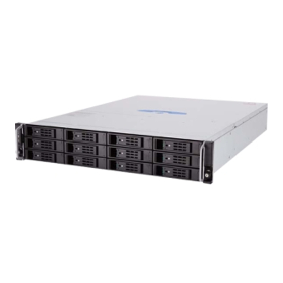
- Page 1 ® Intel Storage System SSR212CC Technical Product Specification Revision 1.2 Storage Group Technical Marketing...
-
Page 2: Revision History
Revision History Intel® Storage System SSR212CC TPS Revision History Date Revision Modifications Number May 16, 2006 Release copy. July 11, 2006 Added RoHS statement, section 6.2. December 06, DDR2 pin number correction 2007 Revision 1.2... - Page 3 Intel disclaims any express or implied warranty, relating to sale and/or use of Intel products including liability or warranties relating to fitness for a particular purpose, merchantability, or infringement of any patent, copyright or other intellectual property right.
-
Page 4: Table Of Contents
Table of Contents Intel® Storage System SSR212CC TPS Table of Contents 1. Feature Summary .......................1 System Components....................5 System Board Feature Set ..................7 Serial ATA (SATA) Host Bus Adapter ..............9 SATA Hot Swap Backplane..................9 Enclosure Management ..................11 1.5.1 Fan Control ......................11 1.5.2... - Page 5 Intel® Storage System SSR212CC TPS Table of Contents Hard Disk Drive Bays ...................25 4.1.1 Hard Disk Drive Carrier ..................26 5. System Interconnection ....................28 Chassis Internal Cables and Connector ...............28 I/O Panel Connectors...................28 SATA HSBP Connectors..................29 5.3.1 SATA 4-Lane Connector ..................29 5.3.2...
- Page 6 ® Figure 1. Intel Storage System SSR212CC................1 ® Figure 2. Intel Storage System SSR212CC Block Diagram ............5 Figure 3. System Components....................6 Figure 4. SATA HSBP Block Diagram..................10 Figure 5. SATA HSBP I C Bus Connection Diagram..............12 Figure 6. Chassis Rear ......................13 Figure 7.
- Page 7 Table 16. Front Panel Power Connector ...................31 Table 17. SATA Host I C Header Pin-out..................31 ® Table 18. Intel Storage System SSR212CC System Office Environment Summary ....35 ® Table 19. Intel Storage System SSR212CC Operating and Non-Operating Environmental Limits..........................36 ®...
- Page 8 List of Tables Intel® Storage System SSR212CC TPS This page intentionally left blank viii Revision 1.2...
-
Page 9: Feature Summary
Low Voltage Intel® Xeon® processor, an Intel® Management Module (IMM), twelve Serial ATA hard disk drive carriers, two Intel® RAID Controller SRCS28X’s, dual Intel® PRO/1000 Network connections, and a single 500 W power supply (dual redundant 1+1 capable). - Page 10 Supported NOTE: For specific drive family and capacities supported, please refer to the SSR212CC Tested Hardware and OS List (THOL). A single Low Voltage Intel® Xeon® processor 2.8 GHz with 800 Processor MHz system bus and 1MB L2 cache. Memory Capacity Expandable to 12 GB maximum, using DDR2-400 memory.
- Page 11 The Power supply enclosure contains one 60mm fan. Power Configuration 500 W continuous, 1+1 redundant power supplies. Intel Storage System SSR212CC ships with one 500W power supply Max AC input current 7.2 Amperes at 110 Vrms, 3.5 A at 220 Vrms (each power supply...
- Page 12 Feature Summary Intel® Storage System SSR212CC Europe, CE Mark EN60950 (complies with73/23/EEC) Germany GS License International IEC60950 (CB Report and Certificate) Nordic Countries EMKO-TSE (74-SEC) 207/94 Russia GOST 50377-92 United States UL– 60950 – CSA 60950 (UL and cUL) Electromagnetic Capability (Class A) (EMC)
-
Page 13: System Components
Intel® Storage System SSR212CC Feature Summary System Components A block diagram of the storage system functional components is shown below. ® Figure 2. Intel Storage System SSR212CC Block Diagram Revision 1.2... -
Page 14: Figure 3. System Components
Feature Summary Intel® Storage System SSR212CC The components included with this storage system are diagrammed below. Figure 3. System Components Revision 1.2... -
Page 15: System Board Feature Set
800 MHz systen bus speed. NOTE: Intel® Storage System SSR212CC only supports a single Low Voltage Intel® Xeon® processor 2.8 GHz with 800 MHz system bus and 1MB L2 cache. Memory Six 240-pin DDR2-400 SDRAM Dual Inline Memory Module (DIMM) sockets Support for up to 12 GB Registered Error Correcting Code (ECC) system memory , using DDR2-400 DIMMs. - Page 16 Intel® Storage System SSR212CC Feature Description Peripheral Four separate and independent PCI buses using Intel® Adaptive Slot Technology for Interfaces high throughput of data via an active 2U riser board: Segment 1 (from baseboard): 64-bit, 133 MHz, 3.3 V, supporting the following •...
-
Page 17: Serial Ata (Sata) Host Bus Adapter
Feature Summary Serial ATA (SATA) Host Bus Adapter ® The Intel Storage System SSR212CC ships with two 8 port PCI-X to SATA Host Bus Adapters (HBA). Each SATA HBA board provides the following feature set: Feature Description Number of ports... -
Page 18: Figure 4. Sata Hsbp Block Diagram
Feature Summary Intel® Storage System SSR212CC The following figure shows the functional blocks of the SATA Hot Swap Backplane. SATA 4-Lane Cable SATA 4-Lane Cable SATA 4-Lane Cable OPS Panel 4 lanes 4 lanes 4 lanes 2x PCI-X SRCS28 8... -
Page 19: Enclosure Management
Enclosure Management The enclosure management controller monitors various aspects of a storage enclosure. Note: Enclosure Management Software is available from Intel for the Red Hat* Enterprise Linux* AS 4, update 2 operating system. Intel® Server Management Software is also available for Microsoft* Windows* Storage Server 2003 R2 and Microsoft* Windows* Server 2003 Enterprise Edition SP1 operating systems. -
Page 20: Hard Disk Drive Leds
Figure 5. SATA HSBP I C Bus Connection Diagram 1.5.4 Hard Disk Drive LEDs ® The Intel Storage System SSR212CC SATA HSBP contains two LEDs for each of the twelve drive slots. Table 1. HDD LED Function Activity Light States Drive Status Idle... -
Page 21: Back Panel I/O Ports And Features
Intel® Storage System SSR212CC Feature Summary Back Panel I/O Ports and Features At the rear of the chassis is a serial management port and two 10/100/1000 Network Interface Card (NIC) connectors. The Input/Output (I/O) connectors are integrated to the back panel. The figure below shows the rear of the storage system. -
Page 22: Front Panel And Hdd Bays
Feature Summary Intel® Storage System SSR212CC Front Panel and HDD Bays Figure 7. Chassis Front and Rear Revision 1.2... -
Page 23: Front/Rear Panel Controls And Indicators
Figure 8. Front Panel Fan Monitoring The fans provided in the Storage System SSR212CC contain a tachometer signal that can be monitored by enclosure management software. 1.10 Rack and Cabinet Mounting Options The chassis was designed to support cabinets that are 19 in (483 mm) wide by up to 36 in (914 mm) deep, and are compliant to the SSI Server Rack specification and EIA 310-D. -
Page 24: Figure 9. Rack Mounting
Feature Summary Intel® Storage System SSR212CC When mounting the system into a cabinet, the front mount brackets are attached to the front of the chassis, and a set of rear support brackets are attached to the back of the cabinet. This allows the weight of the system to be as evenly distributed as possible. -
Page 25: Power Sub-System
Intel® Storage System SSR212CC Power Sub-System Power Sub-System This section provides an overview of the Storage System SSR212CC power supply sub- system; the power supply enclosure and the power supply module. NOTE: The Storage System SSR212CC ships with one 500 Watt power supply module. -
Page 26: Hot Swapping Power Modules
2.1.2 Power Supply Outputs The Storage System SSR212CC power system supports one or two 500 W Power Supply module’s in a 1+1 redundant configuration. The power supply module provides five DC output rails; +12V1, +12V2, +12V3, -12V, +5VSB, while the Power Supply Enclosure provides two DC output rails: +3.3V and +5V. -
Page 27: Output Power/Currents
Intel® Storage System SSR212CC Power Sub-System Output Power/Currents The following table defines power and current ratings for this 500 Watt continuous (606 Watts peak) power supply in 1+0 or 1+1 redundant configuration. The combined output power of both outputs shall not exceed the rated output power. The power supply must meet both static and dynamic voltage regulation requirements for the minimum loading conditions. -
Page 28: Dynamic Loading
Power Sub-System Intel® Storage System SSR212CC 2.3.1 Dynamic Loading The output voltages shall remain within limits specified in Table 9 for the step loading and capacitive loading specified in Table 10, below. The load transient repetition rate shall be tested between 50 Hz and 5 KHz at duty cycles ranging from 10%-90%. The load transient repetition rate is only a test specification. -
Page 29: Table 11. Over Current Protection Limits
Intel® Storage System SSR212CC Power Sub-System condition. 5Vsb shall be protected under over-current or shorted conditions, so that no damage can occur to the power supply. Table 11. Over Current Protection Limits VOLTAGE OVER CURRENT LIMIT (Iout limit) +3.3V <30A <30A... -
Page 30: Over Voltage Protection (Ovp)
Power Sub-System Intel® Storage System SSR212CC 2.5.2 Over Voltage Protection (OVP) The power supply over voltage protection shall be locally sensed. The power supply shall shutdown and latch off after an over voltage condition occurs. This latch shall be cleared by toggling the PSON signal or by an AC power interruption. -
Page 31: System Cooling Module
System Cooling Module System Cooling Module The Storage System SSR212CC includes a cooling module that has three dual rotor 40 mm fans and two single rotor 40 mm fans, mounted in a common frame for ease of maintenance. The fans are mounted in a single fan tray located in the center of the chassis. The Power Supply enclosure contains one 60 mm fan for cooling the power supply modules. -
Page 32: Chassis Bays
Chassis Bays Intel® Storage System SSR212CC Chassis Bays The Storage System SSR212CC chassis provides twelve hard drive bays at the front of the chassis. All hard drive bays may be populated with a carrier-mounted 3.5 inch SATA hard disk drive. -
Page 33: Hard Disk Drive Bays
POST. NOTE: 1) Drive bays 1 thru 6 are controlled by a single Intel® RAID Controller SRCS28X, while drive bays 7 thru 12 are controlled by a second Intel® RAID Controller SRCS28X... -
Page 34: Hard Disk Drive Carrier
Chassis Bays Intel® Storage System SSR212CC Figure 13. Hard Disk Drive Bays 4.1.1 Hard Disk Drive Carrier Each hard drive used in the system must be mounted to a drive carrier, making insertion and extraction of the drive from the chassis very simple. Each drive tray has its own dual purpose... -
Page 35: Figure 14. Hard Drive Carrier Assembly
Intel® Storage System SSR212CC Chassis Bays Figure 14. Hard Drive Carrier Assembly Revision 1.2... -
Page 36: System Interconnection
System SSR212CC. These cables support the twelve expansion drives and provide interconnect between the backplane and the two SATA HBA’s. I/O Panel Connectors The Storage System SSR212CC provides an aperture for the rear I/O ports. The following are the I/O ports available: Two RJ-45 LAN connectors •... -
Page 37: Sata Hsbp Connectors
Intel® Storage System SSR212CC System Interconnection SATA HSBP Connectors 5.3.1 SATA 4-Lane Connector The following table defines the pin-outs of the three SATA 4-Lane Drive Connectors. The first connector carries signals from drive 1 to 4, the second connector is connected to drives 5 to 8 and the third connector connects to drives 9 to 12. -
Page 38: Interposer Connector
System Interconnection Intel® Storage System SSR212CC 5.3.2 Interposer Connector The following table defines the pin-outs of the Interposer Connector. Table 14. Interposer Connector Signal Name Signal Name POWER_SWITCH FAN_PWR_BANK2 FAN_PWR_BANK2 FAN_PWR_BANK2 I2C_SCL_A FAN_TACHO0 I2C_SDA_A FAN_TACHO1 I2C_SCL_B FAN_TACHO2 I2C_SDA_B FAN_TACHO3 COM_TX... -
Page 39: Front Panel Connector
Intel® Storage System SSR212CC System Interconnection 5.3.4 Front Panel Connector The following table defines the pin-outs of the 1x14 Front Panel connector. Table 16. Front Panel Power Connector Signal Name COM_CTS COM_RX COM_TX COM_RTS +5V_OPS +5V_OPS I2C_SDA_OPS I2C_SCL_OPS LED1_OPS/SPARE1 (power) -
Page 40: Regulatory Information
6.1.2 Product EMC Compliance – Class A Compliance Note: Legally the product is required to comply with Class A emission requirements as it is intended for a commercial type market place. Intel targets 10db margin to Class A Limits FCC /ICES-003 - Emissions (USA/Canada) Verification CISPR 22 –... -
Page 41: 6.1.3 Certifications / Registrations / Declarations
Intel® Storage System SSR212CC Regulatory Information 6.1.3 Certifications / Registrations / Declarations UL Certification (US/Canada) CE Declaration of Conformity (CENELEC Europe) FCC/ICES-003 Class A Attestation (USA/Canada) VCCI Certification (Japan) C-Tick Declaration of Conformity (Australia) MED Declaration of Conformity (New Zealand) -
Page 42: 6.1.5 Product Ecology Requirements
All cords and cables shall contain < 100 ppm of cadmium. Restriction of Hazardous Substances (RoHS) Intel has a system in place to restrict the use of banned substances in accordance with the European Directive 2002/95/EC. Compliance is based on declaration that materials banned in the RoHS Directive are either (1) below all applicable substance threshold limits or (2) an approved/pending RoHS exemption applies. -
Page 43: Environmental Limits
Environmental Limits Environmental Limits System Office Environment ® Table 18. Intel Storage System SSR212CC System Office Environment Summary Parameter Limits Operating Temperature 10 degrees celcius to +35 degrees celcius with the maximum rate of change not to exceed 10 degrees celcius per hour. -
Page 44: Environmental Limits
Intel® Storage System SSR212CC Environmental Limits The following table summarizes environmental limits, both operating and non-operating. ® Table 19. Intel Storage System SSR212CC Operating and Non-Operating Environmental Limits Temperature Specification Non-operating -40 degrees celcius to 70 degrees celcius Operating Temperature... -
Page 45: Serviceability And Availability
Intel® Storage System SSR212CC Serviceability and Availability Serviceability and Availability The system is designed to be serviced by qualified technical personnel only. The desired Mean Time To Repair (MTTR) of the system is TBD minutes, including diagnosis of the system problem. To meet this goal, the system enclosure and hardware have been designed to minimize the MTTR. -
Page 46: Calculated Mtbf
Intel® Storage System SSR212CC Calculated MTBF The Mean Time Between Failures (MTBF) for the Storage System SSR212CC is calculated at 27,196 hours operating at 40 degrees C. The following table shows the MTBF numbers for individual components within the chassis, and does not include hard disk drives. - Page 47 Intel® Storage System SSR212CC Glossary Glossary Word / Acronym Definition Ampere Alternating Current Australian Communication Authority ACPI Advanced Configuration and Power Interface ANSI American National Standards Institute AT Attachment Decibel Average Baseboard Management Controller British Thermal Units Celsius ® Compact Flash...
- Page 48 Glossary Intel® Storage System SSR212CC I/O Controller Hub Internet Database Connector Integrated Drive Electronics Intel® Management Module Input/Output iSCSI Internet Protocol Small Computer System Interface Information Technology Equipment Kilo (1.024 x 10 Kilobyte Kilovolt Kilohertz Local Area Network Light-Emitting Diode...
- Page 49 Intel® Storage System SSR212CC Glossary Server System Infrastructure TQFP Thin Quad Flat Pack Terabyte UART Universal Asynchronous Receiver Transmitter Micro Farad (1 x 10 Farads) µF Micro Second (1 x 10 Second) µS Universal Serial Bus Volt Volt-Amp VCCI Voluntary Control Council for Interference...
Need help?
Do you have a question about the SSR212CC and is the answer not in the manual?
Questions and answers