Intel SS4200-E Technical Product Specification
Entry storage system
Hide thumbs
Also See for SS4200-E:
- User manual (126 pages) ,
- Implementation and troubleshooting (12 pages) ,
- Configuration manual (5 pages)

Related Manuals for Intel SS4200-E


Summary of Contents for Intel SS4200-E
- Page 1 ® Intel Entry Storage System SS4200-E Technical Product Specification (Hardware) Intel Order E22057-003 Revision 1.1 Storage Systems Group Marketing...
-
Page 2: Revision History
Intel products are not intended for use in medical, life saving, or life sustaining applications. Intel may make changes to specifications and product descriptions at any time, without notice. -
Page 3: Table Of Contents
Intel® Entry Storage System SS4200-E Table of Contents Table of Contents 1. Feature Summary ......................... 1 System Components ....................6 System Board Feature Set ..................9 Serial ATA (SATA)....................9 Enclosure Management................... 9 1.4.1 Fan Connector and Control ................... 10 1.4.2... - Page 4 Table of Contents Intel® Entry Storage System SS4200-E 5.3.3 Front Panel Connector................... 30 6. Regulatory Information ...................... 31 6.1 Product Regulation Requirements..................31 6.1.1 Product Safety Compliance ................... 31 6.1.2 Product EMC Compliance – Class B Compliance ..........31 6.1.3 Certifications / Registrations / Declarations ............
- Page 5 Intel® Entry Storage System SS4200-E List of Figures List of Figures ® Figure 1. Intel Entry Storage System SS4200-E in optional orientations ........2 ® Figure 2. Intel Entry Storage System SS4200-E Block Diagram ..........6 Figure 3. System Board Connectors..................... 7 Figure 4.
- Page 6 Intel® Entry Storage System SS4200-E List of Tables ® Table 1. Intel Entry Storage System SS4200-E Hardware Feature Summary ......3 Table 2. System Board Components .................... 7 Table 3. Hardware Monitor Features ..................10 Table 4. Analog Voltage Monitor....................10 Table 5.
-
Page 7: Feature Summary
Entry Storage System SS4200-E includes a chassis, Intel Celeron M 420 Processor based board, with a single Intel Celeron M 420 processor, four Serial ATA hard disk ® drive ports, one Intel 82573 Gigabit Ethernet Network controller, 512MB of DDR2 SDRAM ®... -
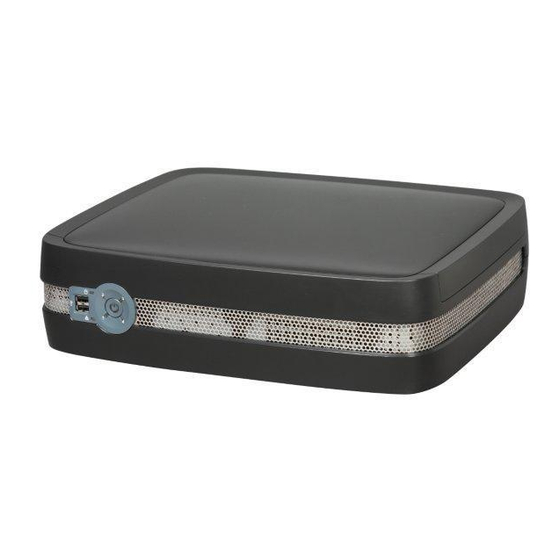
Page 8: Figure 1. Intel Entry Storage System Ss4200-E In Optional Orientations
Feature Summary Intel® Entry Storage System SS4200-E ® Figure 1. Intel Entry Storage System SS4200-E in optional orientations Revision 1.1... -
Page 9: Table 1. Intel
Entry Storage System SS4200-E Hardware Feature Summary Storage Capacity Expandable to 4.0 TB – using four 1000 GB drives NOTE: For specific drive family and capacities supported, please refer to the SS4200-E Tested Hardware and OS List (THOL) Disk Drives 4 Serial ATA (SATA) 3.5 inch SATA 1.5 Gb/s and SATA 3.0 Gb/s... - Page 10 Intel® Entry Storage System SS4200-E The power supply enclosure contains a 40mm x 40mm x 20mm fan. Power 250 W continuous power supply. Intel Entry Storage System Configuration SS4200-E ships with one 250 W power supply Nominal AC input current (PS 1.5 Amperes at 115 Vrms, 0.75 Amperes at 230 Vrms...
- Page 11 Intel® Entry Storage System SS4200-E Feature Summary 89/336/EEC) International CISPR 22 Japan VCCI Korea RRL MIC 1997-41 & 1997-42 Russia GOST 29216-91 & 50628-95 Taiwan CNS13438 United States FCC, Part 15 Revision 1.1...
-
Page 12: System Components
RS232 PCI -E x1 82573E ICH7R South Bridge eSATA PCI -E eSATA SIL3132 SATA2 eSATA controller SATA SATA SATA USB 2.0 SATA USB 2.0 USB 2.0 USB 2.0 ® Figure 2. Intel Entry Storage System SS4200-E Block Diagram Revision 1.1... -
Page 13: Figure 3. System Board Connectors
Intel® Entry Storage System SS4200-E Feature Summary The following diagram shows the system board’s connectors. Figure 3. System Board Connectors The components included with this storage system are diagrammed below. Table 2. System Board Components Reset / Recovery Button DIMM slot LAN Ethernet Port / USB 2.0... -
Page 14: Figure 4. System Components
Feature Summary Intel® Entry Storage System SS4200-E Figure 4. System Components Revision 1.1... -
Page 15: System Board Feature Set
Support for two system fans Serial ATA (SATA) ® The Intel Entry Storage System SS4200-E ships with an ICH7R part which has an integrated 4 port SATA controller. The SATA controller provides the following feature set: Feature Description Number of ports Serial ATA Bus Speed 3.0 Gb/s... -
Page 16: Fan Connector And Control
The first 3 pins of this 4-pin fan connector are backward compatible with a traditional 3-pin fan connector without PWM fan speed control but a 3-pin fan should not be used in the Intel® Entry Storage System SS4200-E. A fan spare kit is available from your supplier which contains the correct fan. -
Page 17: Voltage Monitoring
® The Intel Entry Storage System SS4200-E contains one LED for each of the four hard disk drives. In addition there is a disk activity LED on the front panel. The states for the LEDs are documented in the following table. -
Page 18: Chassis Dimensions And Weight
Feature Summary Intel® Entry Storage System SS4200-E Chassis Dimensions and Weight Table 8. Chassis Dimensions and Weight 4.8 inches Height 122 mm Width across body of enclosure 16 inches 406 mm Depth from flange to rear of enclosure body 13.23 inches... -
Page 19: Back Panel I/O Ports And Features
Intel® Entry Storage System SS4200-E Feature Summary Back Panel I/O Ports and Features At the rear of the chassis is one 10/100/1000 Local Area Network connector, two USB 2.0 ports and two eSATA expansion connectors. The Input/Output (I/O) connectors are integrated into the back panel. -
Page 20: Figure 7. Hard Disk Drive Retention Bracket Assembly
Feature Summary Intel® Entry Storage System SS4200-E Figure 7. Hard Disk Drive Retention Bracket Assembly Revision 1.1... -
Page 21: Front/Rear Panel Controls And Indicators
Intel® Entry Storage System SS4200-E Feature Summary 1.7.1 Front/Rear Panel Controls and Indicators The front/rear panel controls and indicators are defined below: Table 9. Front and Rear Control Button Functions Toggles the system power on/off. If system is operating: Power button •... -
Page 22: Figure 8. Front Panel
Feature Summary Intel® Entry Storage System SS4200-E USB Port 0 NIC Activity LED Disk Drive Activity LED G. Disk Drive 1 Status LED Disk Drive 2 Status LED Power/Status Push-button Disk Drive 3 Status LED Disk Drive 4 Status LED USB Port 1 Figure 8. -
Page 23: Figure 9. Rear Panel
Intel® Entry Storage System SS4200-E Feature Summary NIC Port (1 Gb) Reset Button e-SATA Ports A/C Power USB Port 2 Cable Safety Lock USB Port 3 Figure 9. Rear Panel Revision 1.1... -
Page 24: Power Sub-System
250 Watt power supply. Power Supply ® The Intel Entry Storage System SS4200-E accommodates one 250 Watt (W) power supply. The following table shows the AC input line voltage ranges. Table 11. AC Input Line Voltage Ranges Range... -
Page 25: Figure 10. Power Supply Enclosure
Intel® Entry Storage System SS4200-E Power Sub-System Figure 10. Power Supply Enclosure Revision 1.1... -
Page 26: Power Supply Outputs
® The Intel Entry Storage System SS4200-E power system supports one 250 W power supply. The power supply provides five DC output rails; +3.3V, +5V, +12V, -12V and +5Vsb. Table 12. Power Supply Output Summary (250W 10 second peak ratings) +3.3V... -
Page 27: Voltage Regulation
Intel® Entry Storage System SS4200-E Power Sub-System Voltage Regulation The power supply output voltages will stay within the following voltage limits when operating at steady state and dynamic loading conditions. All outputs are measured with reference to the COM/GND (black wire) Table 14. -
Page 28: System Cooling Fans
® The Intel Entry Storage System SS4200-E includes two cooling fans that are 70mm x 70mm x 15mm single rotor fans, mounted on the rear of the chassis. The Power Supply enclosure contains one 40mm x 40mm x 20mm fan for cooling the power supply module. The current design includes an internal CPU thermal sensor and a thermal sensor on the baseboard near the north bridge. -
Page 29: Hard Disk Drive Retention Assembly
Once placed the captive screw can be pushed and tightened to ensure the disk drive is properly seated in the retention assembly. NOTE: For specific drive family and capacities supported, please refer to the SS4200-E Tested Hardware and OS List (THOL) Figure 11. Disk Drive Insertion and Removal... -
Page 30: Hard Disk Drives
® The Intel Entry Storage System SS4200-E chassis can support up to four SATA, 3.5 inch x 1 inch, hard disk drives. The SATA drives cannot be “electrically” hot-swapped while the system power is applied, i.e., after POST (Power On Self Test). To replace a hard disk drive the system must be powered off prior to removing / replacing the disk drive. -
Page 31: Figure 13. Hard Drive Rvr (Rotational Vibration Reduction) Screw
Intel® Entry Storage System SS4200-E Hard Disk Drive Retention Assembly • to minimize the effects of rotational vibration that has been observed to occur more frequently in hard disk drives of larger capacities. Figure 13. Hard Drive RVR (Rotational Vibration Reduction) Screw... -
Page 32: System Interconnection
The USB ports are connected to the system board via a cable to the connectors. I/O Panel Connectors ® The Intel Entry Storage System SS4200-E provides an aperture for the rear I/O ports. The following are the I/O ports available: • One RJ-45 LAN connector •... -
Page 33: Sata Connectors
Intel® Entry Storage System SS4200-E System Interconnection SATA Connectors 5.3.1 SATA Connector The following table defines the pin-outs of the SATA Drive Connector and the SATA power connector. The first connector carries signals from drive 1, the second connector is connected to drive 2, the third connector connects to drive 3 and the fourth connector connects to drive 4. -
Page 34: Power Connectors
System Interconnection Intel® Entry Storage System SS4200-E 5.3.2 Power Connectors The following tables define the pin-out of the 2x12 power connector for the main power to the board and the 2x2 power connector for the CPU. Table 20. 2x12 Main Board Power Connector Pin-out... -
Page 35: Table 21. 2X12 Cpu Power Connector Pin-Out
Intel® Entry Storage System SS4200-E System Interconnection Table 21. 2x12 CPU Power Connector Pin-out Signal Name +12V +12V PSA2 Revision 1.1... -
Page 36: Front Panel Connector
System Interconnection Intel® Entry Storage System SS4200-E 5.3.3 Front Panel Connector The following table defines the pin-outs of the 2x9 Front Panel connector. Table 22. Front Panel Power Connector Signal Name Signal Name SATA_1_LED_BLU_N LAN_0_LEN_N SATA_1_LED_AMB_N LAN_1_LEN_N SATA_2_LED_BLU_N POWER_ON_LED_GRN_ SATA_2_LED_AMB_N... -
Page 37: Regulatory Information
Intel® Entry Storage System SS4200-E Regulatory Information Regulatory Information 6.1 Product Regulation Requirements Intended Application – This product was evaluated as Information Technology Equipment (ITE), which may be installed in homes, offices, schools, computer rooms, and similar commercial type locations. The suitability of this product for other product categories and environments (such as: medical, industrial, telecommunications, NEBS, residential, alarm systems, test equipment, etc.), other than an ITE application, may... -
Page 38: Certifications / Registrations / Declarations
Regulatory Information Intel® Entry Storage System SS4200-E 6.1.3 Certifications / Registrations / Declarations UL Certification (US/Canada) CCC Certification (China) CE Declaration of Conformity (CENELEC Europe) FCC/ICES-003 (USA/Canada) VCCI Certification (Japan) C-Tick Declaration of Conformity (Australia) MED Declaration of Conformity (New Zealand) -
Page 39: Product Regulatory Compliance Markings
Intel® Entry Storage System SS4200-E Regulatory Information Product Regulatory Compliance Markings The Intel Server Chassis product bears the following regulatory marks. Regulatory Compliance Country Marking cULus Listing Marks USA/Canada CCC Mark China GS Mark Germany CE Mark Europe FCC Marking (Class B) -
Page 40: Product Ecology Requirements
All cords and cables shall contain < 100 ppm of cadmium. European Restriction of Hazardous Substances (RoHS) Intel has a system in place to restrict the use of banned substances in accordance with the Revision 1.1... - Page 41 Intel® Entry Storage System SS4200-E Regulatory Information European Directive 2002/95/EC. Compliance is based on declaration that materials banned in the RoHS Directive are either (1) below all applicable substance threshold limits or (2) an approved/pending RoHS exemption applies. Note: RoHS implementing details are not fully defined and may change.
-
Page 42: Environmental Limits
Intel® Entry Storage System SS4200-E Environmental Limits System Office Environment ® Table 23. Intel Entry Storage System SS4200-E System Office Environment Summary Parameter Limits Operating Temperature 10 degrees celcius to +35 degrees celcius with the maximum rate of change not to exceed 10 degrees celcius per hour. -
Page 43: Environmental Limits
Intel® Entry Storage System SS4200-E Environmental Limits Environmental Limits The following table summarizes environmental limits, both operating and non-operating. ® Table 24. Intel Entry Storage System SS4200-E Operating and Non-Operating Environmental Limits Temperature Specification Non-operating -40 degrees celcius to 70 degrees celcius... -
Page 44: Serviceability And Availability
Serviceability and Availability Intel® Entry Storage System SS4200-E Serviceability and Availability The system is designed to be serviced by qualified technical personnel only. The desired Mean Time To Repair (MTTR) of the system is designed to be less than 60 minutes, including diagnosis of the system problem. -
Page 45: Calculated Mtbf
The predicted Mean Time Between Failures (MTBF) for the Intel Entry Storage System SS4200-E is calculated at 177,000 hours operating at 25 degrees C. The following table shows the MTBF numbers for individual components within the chassis, and does not include hard disk drives, operating at 25 degrees C. -
Page 47: Appendix A: Spares And Accessories
Intel® Entry Storage System SS4200-E Appendix A: Spares and Accessories Appendix A: Spares and Accessories Upgrade and Accessory Parts ® Table 26. Intel Entry Storage System SS4200-E Upgrade and Accessory Parts Product Code MM # Qty. Description FXXSS4200EFAN Chassis Fan... -
Page 48: Glossary
Glossary Intel® Entry Storage System SS4200-E Glossary Word / Acronym Definition Ampere Alternating Current Australian Communication Authority ACPI Advanced Configuration and Power Interface ANSI American National Standards Institute AT Attachment Decibel Average Baseboard Management Controller British Thermal Units Celsius ®... - Page 49 Intel® Entry Storage System SS4200-E Glossary Integrated Circuit I/O Controller Hub Internet Database Connector Integrated Drive Electronics Intel® Management Module Input/Output iSCSI Internet Protocol Small Computer System Interface Information Technology Equipment Kilo (1.024 x 10 Kilobyte Kilovolt Kilohertz Local Area Network...
- Page 50 Glossary Intel® Entry Storage System SS4200-E SOIC Small Outline Integrated Circuit SRAM Static Random Access Memory Server System Infrastructure TQFP Thin Quad Flat Pack Terabyte UART Universal Asynchronous Receiver Transmitter μF Micro Farad (1 x 10 Farads) μS Micro Second (1 x 10...
Need help?
Do you have a question about the SS4200-E and is the answer not in the manual?
Questions and answers