Table of Contents
Advertisement
Prior to operating your 3VCS, please read this manual thoroughly and use
See the glossary on page (P110-112) for the definition's of the special terms
used in this manual.
Application, Export and Reconstruction
1. Use this product in surface models only.
The product described in this manual is subject to regulations of the Ministry of
Radio/Telecommunications and is restricted under Japanese law to such pur-
poses.
2. Exportation Precautions
(a) When this product is exported from Japan, its use is to be approved by the
Radio Law of the country of the destination.
(b) Use of this product with other than models may be restricted by Export and
Trade Control Regulations. An application for export approval must be submit-
ted.
3. Modification, adjustment and replacement of parts.
Futaba is not responsible for unauthorized modification, adjustment and re-
placement of parts of this product.
THE FOLLOWING STATEMENT APPLIES TO THE
RECEIVER (FOR U.S.A.)
This device complies with part 15 of the FCC rules. Operation is subject to the
following two conditions.
(1) This devise may not cause harmful interference, and
(2) This devise must accept any interference received, including interference
that may cause undesired operation.
2
Thank you for purchasing the Futaba 3VCS.
your system in a safe manner.
After reading this manual store it in a safe place.
Advertisement
Table of Contents

Subscribe to Our Youtube Channel
Related Manuals for FUTABA 3VCS


Summary of Contents for FUTABA 3VCS
- Page 1 Thank you for purchasing the Futaba 3VCS. Prior to operating your 3VCS, please read this manual thoroughly and use your system in a safe manner. After reading this manual store it in a safe place. See the glossary on page (P110-112) for the definition’s of the special terms used in this manual.
- Page 2 • The content of the document is susceptible to change without notice. • Although this document is compiled with full care, please inform us if there is anything that is unclear. • Please be sure that Futaba is not responsible to any consequences that customers have used the products.
-
Page 3: Table Of Contents
Table Of Contents For Your Safety As Well As That Of Others..6 Explanation of Symbols ................. 6 High Response System (H.R.S) Precautions ..........6 Operation Precautions .................. 7 Nicad Battery Handling Precautions ............9 Storage and Disposal Precautions ............10 Other Precautions .................. - Page 4 Subtrim ....................71 Servo Reverse ................... 72 Fail Safe/Battery Fail Safe (HRS/PCM Mode Only) ......73 Model Select ..................75 Model Reset ..................77 For Your Safety Model Copy ..................78 As Well As Model Name ..................79 That Of Others Function Select Dial ................
-
Page 5: For Your Safety As Well As That Of Others
For Your Safety As Well As That Of Others Use this product in a safe manner. Please observe the following safety precautions at all times. Explanation of Symbols The parts of this manual indicated by the following symbols are extremely important and must be observed. -
Page 6: Operation Precautions
Operation Precautions Warning Prohibited Procedures Do not operate two or more models Do not operate in the following on the same frequency at the same places. time. -Near other sites where other radio control activity may occur. Operating two or more models at same time on the same frequency will cause interference and loss of -Near people or roads. - Page 7 Caution Prohibited Procedures Do not touch the engine, motor, speed control or any part of the model that will generate heat while the model is operating or immediately after its use. These parts may be very hot and can cause serious burns. Mandatory Procedures Turning on the power switches.
-
Page 8: Nicad Battery Handling Precautions
Nicad Battery Handling Precautions (Only when Nicad batteries are used) Warning Mandatory Procedures Always check to be sure your batter- To recharge the transmitter Nicad , ies have been charged prior to oper- use the special charger made for this ating the model. -
Page 9: Storage And Disposal Precautions
Storage and Disposal Precautions Warning Prohibited Procedures Mandatory Procedures Do not leave the radio system or When the system will not be used for models within the reach of small chil- any length of time store the system dren. with batteries in a discharged state. Be sure to recharge the batteries prior A small child may accidentally operate the system, to the next time the system is used. -
Page 10: Other Precautions
Never use any RF module other than the RF module specially designed for the 3VCS. Futaba will not be responsible for any problems caused by the use of non-Futaba parts or equipment in conjunc- tion with this radio system. Please use parts and equipment that are listed in this instruction manual alone. There is no compatibility between module TZ-FM module for T3VCS and TU-FM module for T3VC. -
Page 11: Before Using
When used with the H.R.S. system, a speed of triple that of an FM system at average response is realized. (Comparison with other Futaba products) The T3VCS transmit- ter is compatible with the H.R.S. system, PCM1024 system, and PPM (FM) system. - Page 12 - Start function (AT-START) When the throttle trigger is set to full throttle simultaneously with starting on slippery roads, the wheels spin and the vehicle does not accelerate (start). Setup the start function allows smooth starting. - Steering speed (ST-SPEED) "When you sense that the steering servo is too fast, etc., the servo operating speed (direction that suppresses the maximum speed) can be adjusted.
-
Page 13: Set Contents
Never use any RF module other than the RF module specially designed for the 3VCS. Futaba will not be responsible for any problems caused by the use of non-Futaba parts or equipment in conjunc- tion with this radio system. Please use parts and equipment that are listed in this instruction manual alone. There is no compatibility between module TZ-FM module for T3VCS and TU-FM module for T3VC. -
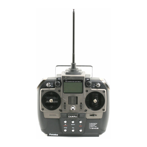
Page 14: Trancemitter T3Vcs
Transmitter T3VCS Nomenclature Antenna LCD screen Pilot lamp Carryng bar Display switch CH3 knob (KNOB) (DSP) (See page 23 for the operat- ing instructions.) Switch(SW2) Switch(SW1) (See page 19 for Power the adjustment instructions.) switch Mechanical (See page 17 for the op- erating instructions.) adjusting Digital trim 3... - Page 15 - Use a commercial earphone. (See page 22 for the handling instructions.) (Use A radio earphone with a 3.5mm diameter plug.) RF module - When the surroundings are noisy during races, etc., you can listen to the alarm tone using an earphone. The alarm tone can also be heard from the transmitter., Sound port TZ-FM...
- Page 16 Digital Trim Operation (Initial settings: DT1: Steering trim, DT2: Throttle trim, DT3: -------) Push the lever in the arrow direction (up/down or right/left). The current position is displayed on the LCD screen. Steering trim display Throttle trim display (*1) For a description of how to display steering EXP on the LCD screen, see page 99.
-
Page 17: Stick Lever Head Adjustment
Neutral Adjuster Operation The neutral adjuster selects the throttle stick neutral position. - (High side):(brake/back side): 5:5 or 7:3 can be selected. Setting Switch to the side that uses the neutral adjuster lever. -This function only changes the throttle stick neu- tral position;... -
Page 18: Stick Tension Adjustment
Mechanical ATL Adjustment Make this adjustment when you want to make the throttle stick brake (back) or high side stroke narrower. Adjustment Brake (back) side Brake (back) side adjustment Make this adjustment by turning the adjusting screw above the stick with a Phillips screw- driver. - Page 19 Ni-cad Battery Replacement The Ni-cad battery is connected by a connector so that it can be removed when you will not be using the transmitter for a long time, or when replacing a dead battery with a spare battery. - Always use an NT8F7000B Ni-cad battery. Ni-cad battery NT8F700B Battery cover...
- Page 20 Cover Charging jack When charging the NT8F700B Ni-cad battery with the special charger, allow about 15 hours for charging. If the transmitter has not been used for some time, cycle the battery by charging and discharging it two or three times. Over current protection The transmitter charging circuit is equipped with an over current protection circuits (1.5A).
- Page 21 The temperature of the RF module will rise slightly during operation. Data Backup The data (transmitter and Data Pac) of each function of the 3VCS transmitter is stored in a memory element that does not require backup battery. Therefore, the transmitter can be used without paying attention to the life of the backup battery.
-
Page 22: Set Data Backup
When a data pack used with another model has been inserted, and initialization is executed by pressing the (+) button when "INITIALIZE?" is displayed on the screen at power ON, the old data is destroyed so the data pack can be used with the 3VCS. Data interchangeability with other models Data is not interchangeable with 3PK, 3VC, and other transmitters other than the 3VCS. - Page 23 "DISP" is dis- played. User name display When the (END) button is held down for 1 second or longer at the initial screen, the Futaba logo and user name are displayed for about 2 seconds. (END) button...
- Page 24 Total timer The total timer shows the accumulated time from last reset. The total time does not change even when the model changes. Reset method 1 In the initial screen state, hold down the (+) and (-) buttons simultaneously for 1 second. * The total timer display counts up from 1 minute to 99hours 59 minutes.
- Page 25 Receiver Nomenclature Crystal When changing the frequency, use the Antenna specified Futaba crystal set. Connectors 1: Steering servo (CH1) 2: Throttle servo (CH2) 3: CH3 servo (CH3) B/C: Power connector/DSC connector R113iP receiver Crystal Antenna When changing the frequency, use the specified Futaba crystal set.
-
Page 26: Installation
Installation Receiver and Servo Connections When connecting and installing the receiver and servos, read the “Installation Safety Precautions” on the next page. Installation When An FET Amp Is Used (MC800CFET Amp) Installation For Gas Powered Models... -
Page 27: Installation Safety Precautions
Installation Safety Precautions Warning Connector Connections Electronic speed control Be sure the receiver, servo, crystal Install the heat sinks where they will and connectors are fully and firmly not come in contact with aluminum, connected. carbon fiber or other parts that con- duct electricity. -
Page 28: Initial Set-Up
If signals are output normally, RF output monitor "RF" will be displayed on the screen. If "RF" is not displayed, check if the transmitter crystal and RF module are installed. If the transmitter is abnoemal or faulty, contact your Futaba dealer. "RF"... - Page 29 2. Modulation Mode Check The T3VCS transmitter output signal format can be changed to match the type of receiver. Check if the modu- lation mode is set to match the receiver used. When using an FM receiver (e.g., R133F), the modulation mode must be set to "PPM".
- Page 30 - Steering dual rate (BT1) check Steering dual rate At initial set-up, steering dual rate (D/R) is assigned to button trim BT1 at the right side of the transmitter. Operate the BT1 button and check if the D/R value dis- played on the screen changes.
-
Page 31: Function Map
Function Map Menu Selection The function set-up screen can be easily selected from the function menu displayed on the LCD screen. The function menu can be selected from among the following 3 levels to match the level of use. To select the level, use the Level Select function (See page 89). -Level 3 (LV3): All functions can be selected. -
Page 32: Direct Selection
Direct Selection The Direct Selection allows instant access to the six functions most frequently used. The function set-up screen can be directly and quickly called with the special buttons for each function of the six functions, they can be freely selected as the Direct Selec- tion Button function. -
Page 33: Functions
Functions End point adjuster/EPA (All channels) Use this when performing steering left and right steering angle adjustments, throttle high side/brake side operation amount adjustment, and channel 3 servo up side/down side operation amount adjustment during linkage. - Correct the maximum steering angle and left and right steering angles when there is a difference in the turning radius due to the characteristics, etc. - Page 34 Calling the setup screen Use the button to * Calling from menu screen select the setup item. (Initial screen) blinks at the current setup item. Use the Setup items button to select the ST-LFT : Steering (left side) menu screen. MENU ST-RGT : Steering (right side) Press the...
- Page 35 Throttle (EPA) adjustment (Preparation) - Before setting the throttle steering angle, set the throttle ATL dial (initial setup: BT2) to the maximum steering 100% angle position 100%. - Select setup item "TH-FWD" and make the following ad- justments: 1 Throttle (forward side) adjustment Turnthe throttle stick fully to the high side and use the (+) or (-) buttons to adjust the throttle angle.
-
Page 36: Steering Exp
Steering EXP/ST-EXP (Steering system) This function is used to change the sensitivity of the steering servo around the neutral position. It has no effect on the maximum servo travel. Racers Tip When the setting is not determined, or the characteristics of the model are unknown, start with 0%. -
Page 37: Steering Speed
Steering Speed/ST-SPEED (Steering system) Quick steering operation will cause momentary understeering, loss of speed, or spin- ning. This function is effective in such cases. Smooth cornering Spin Understeering Steering speed not set Steering speed set Operation - This function limits the maximum speed of TURN direction the steering servo. - Page 38 Steering Speed (ST-SPEED) adjustment (Preparation) - Select setup item "TURN" and make the following ad- justments: 1 "TURN" direction adjustment Setup item switching - Use the (DN) or (UP) button to switch Use the (+) or (-) buttons to adjust the delay the setup item.
-
Page 39: Throttle Exp
Throttle EXP/TH-EXP (Throttle system) This function makes throttle stick high side and brake side direction servo operation quicker or milder. It has no effect on the servo maximum operation amount. For the high side, selection from among three kinds of curves (EXP/VTR/CRV) is also possible. - Page 40 when you want to quicker the rise and use the (-) button to adjust the - side when you want to make the rise milder. 3 When ending adjustment, return to the initial screen by pressing the (END) button 3 times. Adjustment method for VTR curve Adjustment range (Preparation)
- Page 41 TH.P=20% TH.P=80% TH.P=50% 100% (full high) 100% (full high) 100% (full high) 0% (neutral) 0% (neutral) 0% (neutral) +1 ~ +100 (quick) +1 ~ +100 (quick) +1 ~ +100 (quick) -1 ~ -100 (mild) -1 ~ -100 (mild) -1 ~ -100 (mild) Throttle stick forward saide Throttle stick...
- Page 42 Throttle curve Initial values P1 : 17% P2 : 33% P3 : 50% P4 : 67% P5 : 83% Dial / Trim Setting The throttle EXP carve and VTR carve adujustment (Foward side RATE) and(Brake side RATE) can be controlled with button trim BT1, BT2 or digital trim DT3 etc. with the function select dial function.
-
Page 43: Throttle Speed
Throttle speed/TH-SPEED (Throttle system) Sudden trottle stick operation on a slippery road only causes the wheels to spin and the vehicle can- not accelerate smoothly. Setting the throttle speed TH-SPEED/Smooth, quick starts possible function reduces wasteful battery consumption while at the same time permitting smooth, enjoy- able operation. - Page 44 Throttle speed adjustment (Preparation) - Select setup item "MODE" and make the following ad- justments: 1 (Function ON/OFF) Set the throttle speed function to the "ACT" state Function ON/OFF INH(OFF), ACT(ON), ACT(OFF) by pressing the (+) or (-) button. "INH(OFF)" : Function OFF "ACT(ON)"...
-
Page 45: A.b.s. Function
When the A.B.S. function is activated, the LED flashes. Fail Safe Unit When the 3VCS is used with the Futaba fail safe unit (FSU-1), it will operate as described below. - When the FSU-1 is connected to the throttle channel, and the A.B.S. function has been activated, the FSU-1 LED will flash each time the servo operates. - Page 46 Calling the setup screen Setup items Use the button to * Calling from menu screen : Brake return amount select the setup item. (Initial screen) : Delay amount blinks at the current : Cycle speed setup item. Use the MODE : Function ON/Off button to select the : Operation point menu screen.
- Page 47 4 (Cycle speed adjustment) Cycle speed Select setup item "CYC" by pressing the (DN) 1 ~ 30 button once and use the (+) and (-) buttons to Initial value; 10 adjust the speed. - The lower the set value, the faster the cycle speed. 5 (Operation point setup) Operation point Select set item "THP"...
- Page 48 Example of A.B.S. function setting when S9451 / S9351 used (There will be a slight difference depending on the state of the linkage.) - Basic setting ABP: Approx. 30% (If this value is too high, the braking distance will increase.) CYC: 5~7 DTY: 0 (When grip is low: - side, when grip is high: + side) DLY: 10~15%...
-
Page 49: Throttle Acceleration
Throttle acceleration (TH-ACCEL (Throttle system) Gasoline engine cars have a small time lag at both the forward side and brake side because a certain clearance is necessary at the linkage. Reducing this time lag at the transmitter side provides the same sharp response as electric motor cars. Carburetor A slight clearance is required at the linkage, but the throttle acceleration function acts to reduce the time... - Page 50 Throttle acceleration adjustment (Preparation) - Select setup item "FWRD" and make the following ad- justments. 1 (Forward acceleration amount adjustment) Use the (+) and (-) buttons to adjust the accel- Forward acceleration amount 0~100 eration amount. Initial value: 0 "0" : No acceleration "100"...
-
Page 51: Start Function / Engine Cut
Start Function, Engine Cut/AT-START(Throttle system) When the throttle stick is set to full throttle simultaneously with starting when the track is slippery, the car wheels will spin and the car will not accelerate smoothly. When the Start function is activated, merely operating the throttle stick slowly causes the throttle servo to automatically switch from the set throttle position to a preset point so that the tires do no loose their grip and the car accelerates smoothly. - Page 52 Start function adjustment (Preparation) - Select function "AT&SW" at setup item "MODE". Setup items - Select setup item "TH.P" and make the following ad- : READY setting justments. TH.P : Throttle position PRST : Preset position MODE : Function selection Setup item switching - Use the (DN) or (UP) button to switch the setup item.
- Page 53 Engine Cut function adjustment (Preparation) - Use the function select switch function (page ) to select the switch. Setup item switching - Select function "SW" at setup item "MODE". - Use the (DN) or (UP) button to switch the setup item. - Select setup item "PRST"...
-
Page 54: Brake Mixing
Brake mixing/BRAKE MIXING (Throttle, 3rd channel system) Use this mixing when the front and rear brakes must be adjusted independently such as 1/5GP cars, etc. This mixing uses the 2nd channel to control the rear brakes and the 3rd channel to control the front brakes. It is possible to adjust the Brake Return Amount (ABP), Delay Amount (DLY) and Cycle period (CYC) exclusively for the front brake (the 3rd CH). - Page 55 Adjustment buttons Brake mixing adjustment - Use the (+) and (-) buttons to make (Preparation) adjustments. - Press the (+) and (-) buttons simulta- - Select setup item "MODE" and make the following neously (approx. 1 sec) to return to adjustments.
-
Page 56: Idle-Up 1/2
Idle-Up/IDLE-UP 1/2(Throttle system) Use this function to improve the starting characteristics of the engine by raising the idling speed when starting the engine of a gas powered car. Operation Offsets the throttle neutral position to the forward side or brake side. Switch Setting Select the idle-up function ON/OFF switch with the function select switch function. -
Page 57: Timer
Timer/TIMER Use the timer by selecting one of the four timers UP TIMER, DOWN TIMER, LAP TIMER and LAP NAVIGATE timer. UP TIMER UP TIMER function - The UP TIMER can be used to count the time between start and stop, etc. - The timer repeatedly starts and stops each time the switch is operated and accumulates the time between each start and stop. - Page 58 LAP TIMER LAP TIMER function - The LAP TIMER can memorize each lap time of each switch operation. (99 laps) - The race time can be set. Switch operation after the set time by alarm has elapsed automatically stops the timer.. Prealarm can also be set. The passage of time is announced by sounding of a buzzer ([Pee] sound) each minute after starting.
- Page 59 LAP NAVIGATE timer LAP NAVIGATE timer function - This function sounds a buzzer at a fixed interval after the timer starts. Since only the buzzer can be restarted when the switch is pressed during timer operation, this func- tion can be used as the training run, etc. target time. (Lap navigation alarm) The passage of time is announced by sounding of a buzzer ([Pee] sound) every minute after starting.
- Page 60 Up timer setup Switches (Preparation) LAP STA : Start/stop - Use the function select switch function (See page 82) to LAP RES : Lap reset select the switch. - Select "UP TIMER" at setup item "TYPE". * Timer display Setup items Status display : (Indicates the reset state) : Reset state...
- Page 61 DOWN TIMER setup Switches (Preparation) LAP STA : Start/stop - Use the function select switch function (See page 82) to LAP RES : Reset select the switch. - Select "DOWN TIMER" at setup item "TYPE". * Timer display Setup items Status display : (Indicates the reset state.) : Reset state...
- Page 62 Lap timer setup Switches (Preparation) LAP STA : Start/stop - Use the function select switch function (See page 82) to LAP RES : Stop/reset select the switch. - Select "LAP MEMORY" at setup item "TYPE". * Timer display Setup items Status display : (Indicates the reset state.) : Reset state...
- Page 63 Navigation timer setup Switches (Preparation) LAP STA: Start/navigation alarm re - Use the function select switch function (See page 82) to start LAP RES: Stop/reset select the switch. - Select "LAP NAVIGATE" at setup item "TYPE". * Timer display Setup items RST : (Indicates the reset state.) Status display ALRM: Alarm setup...
-
Page 64: Lap List
Lap list/LAP-LIST Call LAP-LIST when checking the lap memory data (each lap time) memorized by lap timer (page 59 ) operation. - After the lap timer is started, the lamp time is sequentially memorized at each switch operation. - When the timer is stopped, the final lap is memorized and the total time is automatically written to the next memory after the final lap. -
Page 65: Programmable Mixing 1/2
Program Mixing 1,2/PRG-MIX1,2 These functions allow you to apply mixing between the steering, throttle, and chan- nel 3 channels. Two programmable mixing systems can be used. The programmable mixing 1 and programmable mixing 2 set-up screens are independent. Additional Functions -When the steering or throttle channel is the master channel (channel that applies mixing), trim data can be added. - Page 66 Program mixing adjustment (Preparation) Switch - Use the function select switch function (page ) to select PRG MIX1 : Program mixing 1 the switch. (as desired) PRG MIX2 : Program mixing 2 - Select setup item "MODE" and make the following ad- justments.
- Page 67 7 (Trim mode setup) Trim mode Select setup item "TRM" by pressing the (DN) OFF, ON Initial value: OFF button once, and use the (+) or (-) button to se- lect the mixing mode. "OFF" : Trim is added. "ON" : Trim is removed. 9 When ending adjustment, return to the initial screen by pressing the (END) button 3 times.
-
Page 68: Tilt Mixing
Tilt mixing/TILT-MIX (Steering system/throttle system) Tilt mixing This mixing uses an outboard engine with a boat, etc. and applies mixing of both directions from rudder (steering) to 3rd channel and from 3rd channel to rudder and allows rudder operation and tilt mixing using 2 servos. Rudder operation by steering wheel and tilt mixing by 3rd channel knob are possible. - Page 69 Tilt mixing adjustment (Preparation) - Select setup item "MODE" and make the following ad- justments. 1 (Function ON/OFF) Set the function to the "ON" state by pressing the Function ON/OFF INH, ON (+) or (-) button. "INH" : Function OFF "ON"...
-
Page 70: Subtrim
Subtrim/SUB-TRIM(All channel) Use this function to adjust the neutral position of the steer- ing, throttle and channel 3 servos. Subtrim shifts the entire servo travel range in the set direc- tion. Use to adjust the neutral position Calling the setup screen Use the button to * Calling from menu screen... -
Page 71: Servo Reverse
Servo Reverse/CH-REV(All channel) This function reverses the direction of operation of the servos related to transmitter steering, throttle, and channel 3 operation. However, when the position set by trim or subtrim shifts from the center, the center becomes the opposite side. Calling the setup screen * Steering * Calling from menu screen... -
Page 72: Fail Safe/Battery Fail Safe (Hrs/Pcm Mode Only)
Fail safe function/FAIL SAFE (This function can only be used with HRS or PCM1024 system receivers.) Fail safe function This function moves the steering, throttle and channel 3 servos to a preset position when the receiver cannot receive the signal from the transmitter for some reason. When the servo operation position is not set, this function operates so that the servos remains in the position they were in immediately before reception was lost. - Page 73 Fail safe function setup (Preparation) - Select the channel to be set. 1 (Servo position setup) When the fail safe function operates, the steering Fail safe function : Steering setting stick, the throttle stick or channel 3 knob remains : Throttle setting in the desired operation position.
-
Page 74: Model Select
Model Select/MDL-SEL Use this function to call a new model number, or to change a set model number, to set new model data. The T3VCS transmitter can store the model data for ten R/C cars. The CAMPac-16K (Option) can store model data for ten more models. The model numbers are 01 to 10 at the transmitter and 11 to 20 at the CAMPac-16K. - Page 75 Model Select 1 (Model No. selection) Model No. Use the (DN) or (UP) button to select the model 01~10: Model memory in the Transmitter 11~20: Model memory in the CAMPac-16K *Current model No. and *Desired model No. and model name model name 2 (Select execution) Press the (+) and (-) buttons simultaneously for...
-
Page 76: Model Reset
Model Reset/MDL-RES This functions resets the contents of the currently called model memory to the initial value. However, it does not reset the Adjuster function (ADJUSTER), System func- tion (SYSTEM), Lap list (LAP-LIST), User name (USR-NAME), Direct selection button (DIRECT CUSTOMIZE), and HRS/PCM/PCM select (MOD-MODE). Calling the setup screen * Calling from menu screen (Initial screen) -
Page 77: Model Copy
Model Copy/MDL-COPY This function copies the entire contents of the currently called model memory to another model memory. Calling the setup screen * Calling from menu screen (Initial screen) Use the button to select the menu screen. MENU Press the button. -
Page 78: Model Name
Model Name/MDL-NAME This function allows you to assign a ten character name to each model memory and an user name (ten character). Calling the setup screen * Calling from menu screen (Initial screen) Model name Use the User name button to select the menu screen. -
Page 79: Function Select Dial
Function select dial/FUNC-DIAL This function allows selection of the function performed by the trim (BT1/BT2), knob (KNB), and digital trimmers (DT1/DT2/DT3), step amount adjustment, and operating direction reversal. Initially set functions DT1: Steering trim DT2: Throttle trim DT3: (Not set) BT1: Dual rate function BT2: ATL function KNB: Channel 3... - Page 80 Calling the setup screen Use the button to * Calling from menu screen select the setup item. (Initial screen) blinks at the current setup item. Use the * Setup item shifts in function -> step button to select the amount -> direction of operation order menu screen.
-
Page 81: Function Select Switch
Function select switch/FUNC-SW This function allows selection of the function to be performed by the switches (SW1/SW2) and setting of the direction, etc. of operation. - The table below shows the functions that can be assigned to each push switch. - SW1: The function of operation can be changed. - Page 82 Calling the setup screen Use the button to * Calling from menu screen select the setup item. (Initial screen) blinks at the current setup item. Use the button to select the Function selection menu screen. MENU Press the button. MENU SELECT Use the button to select the function.
-
Page 83: Dual Rate/Second Dual Rate
Dual rate/ST-D/R (Steering system) Dual rate When the steering angle is too small at under steering at corners while running, adjust at the "+" side and when the steering angle is too large at over steering , adjust at the "-"... - Page 84 Dual rate adjustment (Preparation) - When using the 2nd dual rate function, use the function select switch function (See page 82) to preselect the switch. 1 (Dual rate adjustment) Use the (+) and (-) buttons to adjust the steering D/R rate 0~100% angle.
-
Page 85: Atl Function
ATL Function/TH-ATL(Throttle system) This function adjusts the "-" side when the braking effect is strong and the "+" side when the braking effect is weak. This setting is linked to transmitter grip dial BT2. When BT2 is assigned to another function, set the ATL function with this screen. Operation The throttle brake side (when the throttle stick is pushed forward) brake amount can be adjusted. -
Page 86: Channel 3 Position
Channel 3 Position/CH3-POSI(Channel 3 system) Use this function to set the servo position of the channel 3. This setting is linked to transmitter knob (KNB). When the knob is assigned to an- other function, set the channel 3 position with this screen. Calling the setup screen * Calling from menu screen (Initial screen) -
Page 87: Hrs/Pcm/Ppm Select
HRS/PCM/PPM select/MOD-MODE The signal mode output from the transmitter can be changed. (PPM/PCM/HRS) Receiver When using an FM receiver set to the PPM side, when using a PCM receiver, set to the PCM side and when using an HRS receiver, set to the HRS side. - When the mode was changed and when a model of a different mode was selected, signals are output in the mode set at the point at which the transmitter power was turned back on. -
Page 88: Level Select
Level Select/LEVEL-SEL This function lets you select the function selection menu from among the following 3 levels to match the level of use. (LV-1) (LV-2) (LV-3) - The level can be set for each model. Caution when lowering the level The set value of the functions removed from the menu when the level was lowered remains effective thereafter. -
Page 89: Adjuster
Adjuster/ADJUSTER Steering stick and throttle stick correction can be applied. Use this function when a mechanical offset has occurred for some reason. However, when correction was executed, it may be necessary to recheck the set values of all the setup functions. Calling the setup screen Use the button to... - Page 90 is displayed (figure at the right) and the correction data is not updated. 4 (To terminate execution, press the (END) button.) When ending adjustment, return to the initial screen by pressing the (END) button 3 times. Throttle adjustment (Preparation) - In the state in which the throttle side is selected, select the ad- justment screen by pressing the (SEL) button.
-
Page 91: System Functions
- Liquid crystal screen contrast adjustment (20 steps) - Buzzer sound tone adjustment (OFF, 100 steps) - Pilot lamp display color setup (OFF, 7 colors) - Initial screen display mode setting ("Futaba" display, timer display, servo display, Users name) Setup items... - Page 92 "DISP-SEL) and use the (+) and (-) buttons to NAME select the display mode. "Futaba" : "Futaba" logo is displayed on the initial screen. "TIMER" : Timer screen is displayed on the initial screen. "SRV-VIEW" : Servo operation graph is displayed on the initial screen.
-
Page 93: Direct Selection Button
Direct call/DIRC-CALL The function setup screen can be called from the menu screen or quickly called by using this direct call method. Adjustment can be made quickly by setting frequently used functions at direct call. - Functions can be freely assigned to buttons 1~6 of the screen shown below. - In the initial screen state, after the (UP) and (DN) buttons being pressed, the setup screen is called by simply pressing the assigned button. - Page 94 Calling the setup screen Use the button to * Calling from menu screen select the setup item. (Initial screen) blinks at the current setup item. Use the button to select the menu screen. MENU Press the button. Setup items MENU SELECT Use the button to select the 1: Function assigned to button No.
-
Page 95: Servo View
Servo view/SERVO Servo operation of each channel can be checked. Operation at steering angle adjustment, when a mixing function was set, etc. can be easily checked. The servo view can also be displayed on the initial screen by using the system function (See page 92). -
Page 96: Hrs Esc Set Up
This function is used only when using an FET amp like that shown below with a high response system (HRS System). This function is not used when using a Futaba amp. The frame rate of the transmitter output signal at setup may be counted and the setup mode forcefully ended after a fixed time has elapsed, depending on the commercially available FET amp. - Page 97 FET amp adjustment 1 (Transmitter and amp connection) Connect the transmitter and amp in accordance with the connection diagram on the preceding page. 2 (Amp setup) Press the (+) and (-) buttons simultaneously for at least 1 second. - "NOW ACTIVE" appears on the screen, and a special signal for amp adjustment is output from the transmitter OSC terminal.
- Page 98 Trottle mode/THR-MODE This THR-MODE is convenient for setting conditions; such as changing the move- ment ratio of a servo regardless of the neutral adjuster position and setting the whole throw of a throttle stick for a boat to the forward movement. -In case of "F50/B50"...
-
Page 99: Throttle Mode
Throttle mode function assignment 1 (To select a throttle stick mode) Throttle stick modes Normal : Forward and backward Select "TH-STK" by (UP) or (DN) button. (brake side) movement Then select one of the throttle stick modes by (+) Boat : Forward movement only. -
Page 100: Reference
Reference Ratings *Specifications and ratings are subject to change without prior notice. Receiver R113iP Transmitter T3VCS (3 channels, PCM receiver) (2 sticks system, 3 channels) - Receiving frequencies 27, 29, 40, 41 - Transmitting frequencies 27, 29, 40, or 75MHz band or 41MHz band - Intermediate frequency 455kHz (TZ-FM RF module used) -
Page 101: Optional Parts
FM and single conversion crystal sets with R113iP/R203HF. Warning Use only genuine Futaba crystal. The use of other than Futaba crystal will result in decrease of range as well as loss of control. Transmitter Ni-cad Battery When purchasing a transmitter Ni-cad battery as a spare, etc., use the following:... - Page 102 Since the CAMPac- 16K can be freely carried as a separate unit, the saved data can also be used with other 3VCS transmitters. Do not use any removable memories other than CAMPac-16K. Part Name...
- Page 103 DSC cord When the T3PK transmitter and R113iP or R203HF receiver are connected with the DSC cord, the servos can be operated without transmitting a signal. (DSC function) Part name DSC cord for 3VC DSC jack (Interior) Connection To servos Receiver Connected to B/C To receiver battery...
- Page 104 Changing to Ratchet Type Throttle Stick Changing the throttle stick from the self-return type to ratchet type that stops at an arbitrary position (To make this modification, the optional ratchet plate must be pur- chased.) Case mounting screws 1. Remove the RF module and Ni- Cd battery from the transmitter 2.
-
Page 105: Troubleshooting
Troubleshooting If your system fails to operate or you experience a short range problem or erratic control. Check the table below for reasons you may be having these problems. After you followed the suggestions listed and the problem is not corrected return the sys- tem to our service department for inspection and repair. -
Page 106: Error Displays
LCD screen: Warning When a backup error is generated, immediately stop using the system and request repair from the Futaba Service Center. If you continue to use the system, the transmitter Audible alarm: may malfunction and cause loss of control. - Page 107 LCD screen: Audible alarm: Tone sounds (7 times) and stops (repeated) Data Pac Error If data transfer with the Data Pac was not performed normally, an audible alarm will sound and "ACCESS ERROR" will be displayed on the LCD screen. - To stop the alarm, turn off the power.
-
Page 108: When Requesting Repair (For U.s.a.)
When requesting repair Before requesting repair read this instruction again recheck your system. should the problems continue request as follows. (Information needed for repair) Describe the problem in as much detail as possible and send the letter along with the system in question. -
Page 109: Glossary
Glossary The following defines the symbols and terms used in this instruction manual Band Throttle Stick Frequency that receiver and transmitter operate on. Devise provided on the transmitter to control the throttle. Channel Trim Represents the number of functions the transmitter will Devise that fine adjusts the neutral point of each servo. -
Page 110: Glossary (Lcd Display)
Glossary (LCD Display) The Glossary gives the definition and number of the page that describes the related function for the symbols displayed on the LCD screen. 1:~5: Point 1 through 5 in the throttle curve CH3 POSITION,CH-POSI 3CH position Dual rate function CONTRAST Screen contrast adjustment 2-posion movement for 3CH A kind of the TH-EXP curves... - Page 111 LED-MODE Change LED color Reverse side LEFT, LFT Direction (Left) High frequency output LEVEL SEL Level select function RGT, RGHT Direction (right) LHT-MODE Backlight mode setting TIMER is reset. LHT-TIME Backlight time setting TIMER is on duty. LOW BATTERY Warning of the low battery SBT-1, SBT1 Sub-trim (CH1) M1~M10...
- Page 112 FUTABA CORPORATION Makuhari Techno Garden Bldg., B6F 1-3 Nakase, Mihama-ku, Chiba 261-8555, Japan Phone: (043) 296-5119 Facsimile: (043) 296-5124 2004, 12 ©FUTABA CORPORATION...
Need help?
Do you have a question about the 3VCS and is the answer not in the manual?
Questions and answers