Table of Contents
Advertisement
Advertisement
Table of Contents

Related Manuals for FUTABA 3PDF


Summary of Contents for FUTABA 3PDF
- Page 1 3PDF Instruction Manual 1M23N02102...
- Page 2 -No part of this manual may be reproduced in any form without prior permission. -The contents of this manual are subject to change without prior notice. -This manual has been carefully written, please write to Futaba if you feel that any corrections or clarifica- tions should be made.
-
Page 3: Table Of Contents
3PDF Table of Contens For your safety For your safety as well as Function Map as well as that of others. that of others. Function Mode Group System Mode Group Explanation of Symbols Direct Mode Group Operation Precautions Nicad Battery Handling Precautions... -
Page 4: For Your Safety As Well As That Of Others
3PDF For your safety as well as that of others. Use this product in a safe manner. Please observe the following safety precautions at all times. Explanation of Symbols The parts of this manual indicated by the following symbols are extremely important and must be observed. - Page 5 Mandatory Procedures Extend the transmit- When changing the frequency, be Extend to ter antenna to its full sure to always use genuine Futaba full length length. crystal sets (transmitter and receiver) as specified in this manual. (Chang- If the transmitter antenna is not...
-
Page 6: Nicad Battery Handling Precautions
The fuel, motor spray, waste oil and exhaust will pen- Futaba will not be responsible for problems caused by etrate and damage the plastic. the use of other than Futaba genuine parts. Use the parts specified in the instruction manual and catalog. -
Page 7: Storage And Disposal Precautions
Storage and Disposal Precautions Warning Prohibited Procedures Mandatory Procedures Do not leave the radio system or When the system will not be used for models within the reach of small chil- any length of time store the system dren. with batteries in a discharged state. Be sure to recharge the batteries prior A small child may accidentally operate the system, to the next time the system is used. -
Page 8: Features
3PDF Prior to operation Features -Multiple Model Memory (3 Models) A model name can be assigned each memory using six alphabetic, numeric and symbolic characters. (P30) Digital Trim Memory will recall all trim settings. As you go from model to model memory all trim settings will not have to be reset. -
Page 9: Set Contents
Set Contents After opening the container, check the contents for the following items. The contents will vary with the system purchased. Transmitter System with System with / Receiver 2 servos 1 MC210CB Transmitter T3PDF (x1) R113F (x1) Receiver Servo S3003 (x2 ) S3003 (x1) E.S.C. -
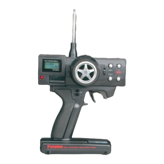
Page 10: Nomenclature / Handling
Nomemclature / Handling Transmitter T3PDF (Front) Antenna Steering Trim Steering Wheel Throttle Trim Channel 3 Lever Edit Keys Screen MULTI FUNCTION DISPLAY MODE Power LED DOT MATRIX RESET SELECT Power Switch POWER Mechanical ATL CHARGE Adjustment Hole Charging Jack Steering D/R Lever Throttle Trigger Throttle ATL Lever Grip Handle... - Page 11 If the displayed voltage is low or does not light all, check the batteries for in- <Converting to Nicad Batteries> sufficient contact or incorrect battery Purchase Futaba Part Number NT- polarity. 8JY to convert your transmitter to Nicad use.
- Page 12 Receiver R113F Crystal Output Connector FP-R113F “1”: Steering Servo (Ch1) “2”: Throttle Servo (Ch2) Antenna “3”: CH3 Servo (CH3) Power Connector Servo S3003 <Accessories> Mounting Flange The following accessories are sup- Servo Horn plied with the system; -Spare servo horns: Use to match your application.
-
Page 13: Digital Trim Operating Instructions
Digital Trim Operating Instructions To operate the digital trim push the trim lever to the left or right. -A “Tone” will indicate each step. -When the trim movement reaches its maximum travel the “tone” will change pitch. -When a trim lever is moved the current trim position will be displayed on the LCD screen. -
Page 14: Display / Key Operation
Display / Key Operation Initial Screen (Normal Screen) Model Number Display (1~3) Model name display (only when set) Displays the number cur- (6 characters) rently in use. Batttery voltage display Displays the current transmitter battery voltage lavel. LCD screen contrast adjustment Turn on the transmitter power switch , the screen will show the current settings. -
Page 15: Warning Displays
Warning When a memory error is generated immediately stop operating the system and request repair by the Futaba service center. If you continue to operate the system control may be erratic and cause of control is highly likely. Precautions when turning the power switches off and on. -
Page 16: Receiver And Servo Connections
3PDF Assembly Receiver and Servo Connections Connect and install the receiver and servos in accordance with the "Assembly Safety Precautions" on the next page. When a E.S.C. is used (MC210CB) Connect to motor Connect to battery MC 210CB Power Switch E.S.C. -
Page 17: Assembly Safety Precautions
Assembly Safety Precautions Warning Connector Connections Electronic speed control Be sure the receiver, servo and bat- Install the heat sinks where they will tery connectors are fully and firmly not come in contact with aluminum, connected. carbon fiber or other parts that con- duct electricity. -
Page 18: Preparations Prior To Setting Transmitter
Preparations Prior to Setting Transmitter Prior to making any setting on the transmitter check the following items. Steering Trim Lever TRIM.Pos Throttle Trim Lever TRIM.Pos Lever A D/R .Pos L100R100 Lever B ATL .Pos Preparations Prior to Setting Transmitter To set the steering trim to neutral, push the channel 1 trim lever to the left or right. -
Page 19: E.s.c. Mc210Cb Adjustment
E.S.C. MC210CB Adjustment *Use the accessory mini screwdriver to make adjust- ments. Preparation Set the transmitter servo reversing switch to the normal position. Turn the high point trim fully clockwise. MC210CB Fully Clockwise Neutral Adjustment Have the throttle trigger at neutral. Set the neutral trim to the point where the monitor lamp goes off. -
Page 20: Function Map
3PDF Function Map When the MODE key and the SELECT key are When the Mode key is pressed from the initial pressed simultaneously at the initial screen., screen where the voltage is displayed , this will this will call the SYSTEM MODE. -
Page 21: Direct Mode Group
When a lever is operated from an arbitrary screen, that screen is dis- played for about 5 seconds. TRIM.Pos * However, when the system mode setup screen is displayed, the di- Steering Trim rect mode screen is not displayed Position even if a lever is operated. -
Page 22: Steering Trim
3PDF Description of Functions Steering Trim The steering neutral position can be adjusted by moving Steering Trim the steering trim lever to left or right. Lever Use this function to make your model run in a straight line. At the initial screen where the Model number and... -
Page 23: Throttle Trim
Throttle Trim The Throttle neutral position can be adjusted by moving the throttle trim lever up or down. At the initial screen where the Model number and voltage are displayed the Throttle Trim setting can be viewed by pressing the trim lever up or down. -
Page 24: Servo Reverse
Servo Reverse This function will reverse the rotation direction of the Initial Screen 10.5V Steering, Throttle and Channel 3 servos. Select key SELECT pressed first MODE If the trim position is not set to 0. The servo will SYSTEM shift the same amount off neutral on the opposite MODE side when the servo is reversed. -
Page 25: Steering Atv
Steering ATV Use this function to limit the servo movement to the left Initial Screen 10.5V or right. The servo travel to each side can be indepen- dently adjusted. This feature will compensate for any MODE difference in right or left turning angles or radius due to FUNCTION the characteristics of your model. -
Page 26: Throttle Atv
Throttle ATV This function is used to adjust the forward and brake side Initial Screen 10.5V servo travel. Each direction can be adjusted independent of each other. Use this feature to set the throttle servo MODE travel. FUNCTION MODE Warning Be sure that your throttle linkage does not apply exces- MODE sive force to the servo. -
Page 27: Steering D/R
Steering D/R (Description when D/R lever is assigned to GDA ) D/R Lever This function is used to limit the steering servo travel. This feature will limit the servo travel equallyin both directions. If the car tends to understeer (push) when cornering add servo travel. -
Page 28: Throttle Atl
Throttle ATL (Description when ATL is assigned to GDB) This function is used to adjust the brakes. If you are getting to much brake in the car set the ATL number to lower setting. When you need more brakes set the number to a higher setting. -
Page 29: Steering Exponential
Steering Exponential Use this function to change the sensitivity of the steering Initial Screen 10.5V servo around neutral. The - side will make the servo less sensitive around neutral. The + side will make the servo MODE more sensitive around the neutral. FUNCTION MODE Racer Tip... -
Page 30: Throttle Exponential
Throttle Exponential This function will allow you to change the sensitivity of Initial Screen 10.5V the throttle servo. The + side will make the servo reac- tion move sensitive while - side will make it less sensi- MODE tive. FUNCTION MODE Racers Tip When track conditions are good experiment with the +... -
Page 31: Model Select
Model Select The 3PDF can store the data for 3 different models. Initial Screen 10.5V MODE FUNCTION MODE MODE Access this function by pressing the MODE key MDL.SEL from the initial screen. MODE TH.EXP MODE MODE ST.ATV MODE (Model Select Function>... -
Page 32: Model Name
Model Name Up to 6 characters can be used to assign each model Initial Screen 10.5V memory a name. Alphabetic, numeric and symbols can Select key SELECT be used. This will make your model memos easy to tell pressed first MODE apart. -
Page 33: Lever Function Select
Lever Function Select This function will allow you to assign different functions Initial Screen 10.5V to the levers. The steering D/R Throttle ATL and Chan- SELECT Select key nel 3 can be assigned to these levers. pressed first MODE SYSTEM MODE Access the System mode by pressing the Mode key and Select key simultaneously from the ini-... -
Page 34: Channel 3 Function Selection
Channel 3 Function Selection The channel 3 operation can be selected from the follow- Initial Screen 10.5V ing functions. Select key SELECT pressed first MODE 1P: The third channel will operate like a self return switch. The servo will move from servo position (P1) when the lever is not operated to servo SYSTEM MODE position (P2) while the lever is operated. -
Page 35: Ch3 Position Setting
CH3 Position Setting (Description is with the CH3 lever position in the initial setting) CH3 Lever * Before using this function to select the servo position to used with each function. Select the CH3 operation function selection function. (P32). (When LIN Type is Set) MODE RESET The maximum travel can be set... -
Page 36: Reference
(Excluding heat sinks and protruding parts) Size: 0.77" x 1.59" x 1.41" Weight: 2.55oz Weight: 1.5oz. Optional Parts The following parts are sold separately as optional parts. Refer to the Futaba catalog for more information. Transmitter Nicad Battery: Futaba Crystal Sets: NT-8JY Nicad battery Pack... -
Page 37: Troubleshooting
Loose -> Push the crystal in firmly tently Wrong Band -> Be sure the transmitter and receiver frequencies match Wrong type or brand -> Replace with genuine Futaba crystal o p e r a t i n g range is short... -
Page 38: Glossary
Glossary The following defines the symbols and terms used in this instruction manual Band Throttle Frequency that receiver and transmitter oper- Devise that controls the air mixture at the en- ate on. gine intake. When opened a large air mixture is sucked in and the engine speed increases.
Need help?
Do you have a question about the 3PDF and is the answer not in the manual?
Questions and answers