Table of Contents
Advertisement
Quick Links
Advertisement
Table of Contents

Related Manuals for FUTABA 3GR-2.4G


Summary of Contents for FUTABA 3GR-2.4G
- Page 1 3GR-2.4G 3-channel, FASST Radio control system for Car 1M23N18005...
- Page 2 Prior approval of the appropriate goverment authori- ties may be required. If you have purchased this product from an exporter outside your country, and not the authorized Futaba distributor in your country, please contact the seller immediately to determine if such export regulations have been met.
- Page 3 •No part of this manual may be reproduced in any form without prior permission. •The contents of this manual are subject to change without prior notice. •This manual has been carefully written. Please write to Futaba if you feel that any corrections or clarifications should be made.
-
Page 4: Table Of Contents
Table Of Contents For Your Safety As Well As That Of Others... 6 Explanation of Symbols ................6 2.4GHz System Precautions ................. 6 Operation Precautions .................. 7 NiCd Battery Handling Precautions ............. 9 Storage and Disposal Precautions ............10 Other Precautions ..................11 Before Using ............ - Page 5 Model Select ..................48 Timer ....................49 (System Functions) Model Copy ..................51 For Your Safety Model Reset ..................52 As Well As Model Name ..................52 That Of Others HRS/PPM Select ................53 Function Select Switch ..............54 Function Select Lever ............... 55 Condition 2 Selection ................
-
Page 6: For Your Safety As Well As That Of Others
Mandatory Procedures Always use R603FF under the following conditions; Power supply: 6V Nicd battery (PPM/HRS mode) Servo: 6V type Futaba Digital Servo (HRS mode) If these conditions are not followed, control may be impossible or the servo may be damaged. -
Page 7: Operation Precautions
Operation Precautions Warning Prohibited Procedures Do not operate in the following Do not operate outdoors on rainy places. days , run through puddles of water, or use when visibility is limited. -Near people or roads. Should any type of moisture (water or snow) enter any -On any pond when boats are present. - Page 8 (Turning on the power switches) Always check the throttle stick on the transmitter to be sure it is at the neutral position. 1. Turn on the transmitter power switch. 2. Turn on the receiver or speed control power switch. (Turning off the power switches) Always be sure the engine is not running or the motor is stopped.
-
Page 9: Nicd Battery Handling Precautions
NiCd Battery Handling Precautions (Only when NiCd batteries are used) Warning Mandatory Procedures Always check to be sure your batter- To recharge the transmitter and/or re- ies have been charged prior to oper- ceiver NiCd batteries, use the special ating the model. charger made for this purpose. -
Page 10: Storage And Disposal Precautions
Storage and Disposal Precautions Warning Prohibited Procedures Do not leave the radio system or models within the reach of small children. A small child may accidentally operate the system. This could cause a dangerous situation and injuries. NiCd batteries can be very dangerous when mishandled and cause chemical damage. Caution Prohibited Procedures Mandatory Procedure... -
Page 11: Other Precautions
The fuel, motor spray, waste oil and exhaust will pen- controls),NiCd batteries and other op- etrate and damage the plastic. tional accessories. Futaba will not be responsible for problems caused by the use of other than genuine Futaba parts. Use the parts specified in the instruction manual and catalog. -
Page 12: Before Using
This system is based on the combination of the newly developed 2.4GHz transmitter and its corresponding receiver. The system utilizes the 2.4GHz-SS radio communica- tion and an ultra small antenna. In addition, the system inherits Futaba's unique HRS (High Response System). - Page 13 - Digital trim: Steering trim, Throttle trim, Steering D/R The current position is displayed on the LCD screen for about three seconds when each digital trim is operated. - Function select lever function (FNC-DT1/DT2/DT3/DT4) This function assigns a function to levers (digital trims, grip levers). Trim positioning at each model call is unnecessary because all the levers are digital.
-
Page 14: Set Contents
Always use only genuine Futaba transmitter, receiver, FET amp, NiCd battery and other optional parts. Futaba will not be responsible for damage caused by other than genuine Futaba parts and components. Use only the genuine Futaba parts and components listed in the instruction manual and catalog. -
Page 15: Nomenclature (Transmitter/Receiver/Servo)
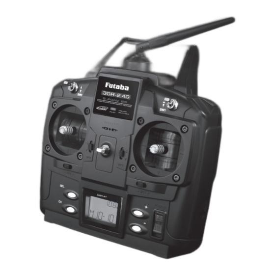
Transmitter T3GR-2.4G Warning Caution Never hold the antenna alone. Adjust the antenna vertically to the ground. Hold the carrying handle. Otherwise the an- tenna may be damaged. Otherwise, the operating range may become shorter. Carrying handle Neck strap hook Antenna Pilot lamp Switch ( SW2) Switch (SW1) - Page 16 Digital Trim Operation (Initial settings: DT1: Steering trim, DT2: Throttle trim, DT3=Steering D/R, DT4=Throttle ATL) Push the lever to the left or right (up or down). The current position is displayed on the LCD screen for about three seconds when each digital trim is operated.
- Page 17 Battery Replacement For dry cell battery system Load the eight batteries in accordance with the polarity markings on the battery holder. (8 AA Size Batteries) Battery Replacement Caution Remove the battery cover from Always be sure you reinsert the bat- the transmitter by sliding it in teries in the correct polarity order.
- Page 18 For NiCd battery system - Always use an NT8F700B NiCd battery. NiCd battery NT8F700B Charging jack Charging the NiCd Battery Plug the transmitter cord of the AC outlet special charger into the charg- ing jack on the side of the trans- Charger mitter.
- Page 19 Warning Never plug it into an outlet of other Do not insert and remove the than indicated voltage. charger when your hands are wet. Plugging the charger into the wrong outlet may re- It may cause an electric shock. sult in an explosion, sparking, or fire. Always use the special charger or a quick charger for digital pro- portional R/C sets to charge a digital proportional R/C set NiCd battery.
- Page 20 Receiver Connectors 3: CH3 servo (CH3) 2: Throttle servo (CH2) 1: Steering servo (CH1) B/C: Power connector/DSC connector RS232C: (for factory use only) Antenna Coaxial cable R603FF receiver For the receiver, servos, and other connections, see page 21.
-
Page 21: Installation
Installation Receiver and Servo Connections When connecting and installing the receiver and servos, read the “Installation Safety Precautions”. Installation For Electric Powered Models R603FF Installation For Gas Powered Models R603FF Installation Safety Precautions Receiver Antenna Installation Antenna tube Install the R603FF receiver on the car as follows: Note: The operating range may become shorter, depending on where the receiver and the antenna are mounted. - Page 22 Warning Connector Connections Servo Throw Be sure the receiver, servo and con- Operate each servo over its full stroke nectors are fully and firmly con- and be sure the linkage does not bind nected. or is loose. If vibration from the model causes a connector to work The continuous application of unreasonable force to a loose while the model is in operation, you may lose servo may cause damage and excessive battery...
-
Page 23: Initial Set-Up
Initial Set-Up How to link the transmitter and the receiver Each transmitter has an individually assigned, unique ID code. In order to start opera- tion, the receiver must be linked with the ID code of the transmitter with which it is being paired. -
Page 24: Preparations (Transmitter)
Preparations (Transmitter) Before setting the transmitter functions, check and set items below. (Display when power switch is turned on) Turn on the transmitter power. Modulation mode PP: PPM mode HRS: HRS mode (displayed for about one second) Battery voltage Model name Model number 1. - Page 25 3. Trims Initial Set-Up - Steering trim (DT1) check Steering trim At initial set-up, steering trim is assigned to digital trim position DT1. Operate the DT1 lever and check if the steering trim value on the screen changes. After checking the trim, set the trim value to the center (0) position.
- Page 26 - Steering dual rate (DT3) check Steering D/R At initial set-up, steering dual rate is assigned to digital value trim DT3. Operate the DT3 lever and check if the D/R value displayed on the screen changes. After checking D/R, set the steering dual rate to 100%. - Throttle ATL (DT4) check At initial setting, throttle ATL is assigned to digital Throttle ATL...
- Page 27 (Set-Up Procedure When Installed In a Car) When installing the servos in a car, performing function set-up in the following order is recommended. 1. Set up the servo trims (page 22). 2. Set the servo direction of operation using the Reverse function.
-
Page 28: Function Map
Function Map Power switch turned on The current modulation mode is Press "SEL" key to select displayed for about two seconds. the desired function screen. Press it for one second or more to scroll to the opposite direction. (Initial Screen) Press "CH"... - Page 29 System Functions Turn on the power switch while pressing "SEL" key. Press "SEL" key to select the desired function screen. Press it for one second or more to scroll to the opposite direction. Model Copy Throttle Neutral Adjuster Model Reset LED Mode Selection Model Name Condition 2 Selection...
-
Page 30: Functions
Functions End point adjuster/EPA Use this when performing left and right steering angle adjustments, throttle high side/ brake side operation amount adjustment, and channel 3 servo up side/down side op- eration amount adjustment during linkage. - Corrects the maximum steering angle and left and right steering angles when there is a difference in the turning radius due to the characteristics, etc. - Page 31 Press "CH" key to select the next set- Calling the setup screen up screen. (Initial screen) (Setup screen) Press "SEL" key to select the Setup items Adjustment range desired function screen. ST-L.F.U : Steering (left side) 0~120% (each channel, each direc- ST-R.B.D : Steering (right side) tion) TH-L.F.U : Throttle (forward side)
- Page 32 Throttle (brake side/reverse side) adjustment Pull the throttle stick fully to the brake side and use the (+) and (-) buttons to adjust the steering angle. However, when using an FET amp, set to 100%. When adjusting the EPA of another channel immediately after this, see the adjustment method for that channel.
-
Page 33: Steering Speed
Steering Speed/SPD Quick steering operation will cause momentary understeering, loss of speed, or spin- ning. This function is effective in such cases. Smooth cornering Spin Understeering Steering speed not set Steering speed set Operation - This function limits the maximum speed of TN direction the steering servo. -
Page 34: Steering Exp / Throttle Exp
Steering EXP, Throttle EXP / EXP This function is used to change the sensitivity of the steering servo around the neutral position and makes throttle stick high side and brake side direction servo operation quicker or milder. It has no effect on the maximum servo travel. Racers Tip When the setting is not determined, or the characteristics of the model are unknown, start with 0%. - Page 35 Throttle EXP Adjustment (Preparation) - Select setup item "EXP-FW" and make the following adjustments: Forward side adjustment Use the (+) button to adjust the + side when you want to quicken the rise and use the (-) button to adjust the - side when you want to make the rise milder.
-
Page 36: Function
When the A.B.S. function is activated, the LED flashes. Fail Safe Unit When the 3GR-2.4G system (PPM mode) is used with the Futaba fail safe unit (FSU), it will operate as described below. - When the FSU is connected to the throttle channel, and the A.B.S. function has been activated, the FSU LED will flash each time the servo operates. - Page 37 A.B.S function adjustment (Preparation) - Select setup item "ABS-MD" and make the following adjustments: (Function ON/OFF) Set the function to the active state by pressing the (+) or (-) button. OFF : Function OFF ON : Function ON (Brake return amount adjustment) Select setup item "ABS-PT"...
-
Page 38: Throttle Acceleration
Throttle Acceleration / ACC Gasoline engine cars have a small time lag at both the forward side and brake side because a certain clearance is necessary at the linkage. Reducing this time lag at the transmitter side provides the same sharp response as electric motor cars. Carburetor A slight clearance is required at the linkage, but the throttle acceleration function acts to reduce the time... - Page 39 Throttle acceleration adjustment (Preparation) - Select setup item "ACC-FW" and make the following adjustments. (Forward acceleration amount adjustment) Use the (+) and (-) buttons to adjust the acceleration amount. "0": No acceleration "100": Maximum acceleration (Approximately 1/2 of the forward side steering angle) (Brake side acceleration amount adjustment) Select setup item "ACC-BK"...
-
Page 40: Brake Mixing
Brake Mixing / BMX Use this mixing when the front and rear brakes must be adjusted independently, such as in 1/5GP cars, etc. This mixing uses the 2nd channel to control the rear brakes and the 3rd channel to control the front brakes. Operation - When braking, mixing is applied to 2nd channel and to 3rd channel. -
Page 41: Programmable Mixing
Programmable Mixing / PMX This function allows you to apply mixing between the steering, throttle, and channel 3 channels. Calling the setup screen Mixing amount Setup items (Initial screen) -100~+50~+100 PMX-RT(L.F.U): Mixing rate (Left Initial value: +50 side) Adjustment buttons PMX-RT(R.B.D.): Mixing rate (Right - Use the (+) and (-) buttons to make side) -
Page 42: Fail Safe/Battery Fail Safe (Hrs System Only)
Fail Safe Function/FAIL SAFE (This function can only be used with HRS system.) Fail safe function This function moves the steering, throttle and channel 3 servos to a preset position when the receiver cannot receive the signal from the transmitter for some reason. When the servo operation position is not set, this function operates so that the servos remain in the position they were in immediately before reception was lost. -
Page 43: Trim
Steering Trim, Throttle Trim / TRM Steering neutral adjustments and throttle neutral adjustments during a run can be made by moving the trim lever to the left or right (the up or down). This setting is linked to transmitter digital trim lever DT1 and DT2. When DT1 or DT2 is assigned to another function, set the trim function with this screen. -
Page 44: Steering D/R
Steering Dual Rate / D/R-ST When the steering angle is too small at under steering at corners while running, in- crease the rate. When the steering angle is too large at over steering, decrease the rate. The setup here is linked with transmitter digital trim DT3. Adjustments can be made at this screen even if DT3 is assigned to another function. -
Page 45: Channel 3 Position
Adjustment buttons Setup Item ATL-BK: Throttle ATL position - Use the (+) and (-) buttons to make adjustments. ATL position - Press the (+) and (-) buttons simulta- 0 ~ 100% neously (approx. 1 sec) to return to the Initial value: 100% initial screen. -
Page 46: Subtrim
Subtrim / SBT センターを出すため Use this function to adjust the neutral position of the steer- に使用する ing, throttle and channel 3 servos. Subtrim shifts the entire servo travel range in the set direc- tion. Use to adjust the neutral position Press "CH"... -
Page 47: Servo Reverse
Servo Reverse / REV This function reverses the direction of operation of the servos related to transmitter steering, throttle, and channel 3 operation. However, when the position set by trim or subtrim shifts from the center, the center becomes the opposite side. Press "CH"... -
Page 48: Model Select
Model Select / SEL Use this function to call a new model number, or to change a set model number, to set new model data.The T3GR-2.4G transmitter can store the model data for ten R/C cars. Calling model memories of different modulation modes (HRS, PPM) After the new model is called, signals are still output in the old model modulation mode until the transmitter power is turned off. -
Page 49: Timer
Timer / TIMER Use the timer by selecting from UP Timer or DOWN timer. UP TIMER function - The UP TIMER can be used to count the time between start and stop. - The timer repeatedly starts and stops each time the switch is operated and accumulates the time between each start and stop. - Page 50 (Linking start with the throttle stick) Select setup item "TIMER" and press the (+) and (-) buttons simulta- neously for about 1 second. A beeping sound is generated and "RDY" displays at the timer display and the system enters the RDY state. Stick operation starts the timer.
-
Page 51: (System Functions) Model Copy
Model Copy / CPY This function copies the entire contents of the currently called model memory to another model memory. Calling the setup screen 1. Turn on the power switch 2. Next, use "SEL" key to select while pressing "SEL" key. the desired function screen. -
Page 52: Model Reset
Model Reset / CLR This functions resets the contents of the currently called model memory to the initial value. However, it does not reset the lap time memory, HRS/PPM select, and LED mode selection. Calling the setup screen 1. Turn on the power switch 2. -
Page 53: Hrs/Ppm Select
HRS/PPM Select / MOD The signal mode output from the transmitter can be changed. (PPM/HRS) - When the mode was changed and when a model of a different mode was selected, signals are output in the mode set at the point at which the transmitter power was turned back on. -
Page 54: Function Select Switch
Function Select Switch / FNC-SW This function allows selection of the function to be performed by the switches (SW1/SW2). Settable functions (SW1) Settable functions (SW2) OF: (function off) OF: (function off) 3C: Channel 3 3C: Channel 3 MX: Programmable mixing MX: Programmable mixing TM: Timer switch Calling the setup screen... -
Page 55: Function Select Lever
Function Select Lever / FNC-DT This function allows selection of the function performed by digital trim (DT1/DT2/ DT3/DT4). Initially set functions Settable functions DT1: Steering trim ST: Steering trim DT2: Throttle trim TH: Throttle trim DT3: Dual rate function DR: Steering D/R DT4: ATL function AT: Throttle ATL E1: Steering EXP... -
Page 56: Condition 2 Selection
Condition 2 Selection / COND2 Condition 2 Selection In specific functions, two rates can be set up, and switched with the switch (SW1) simultaneously during a run. If this function is activated, SW1 is used only for this function, and it becomes impos- sible to use it for other functions automatically. -
Page 57: Throttle Neutral Adjuster
Throttle Neutral Adjuster / THR-NT You can select your desired throttle neutral position. (7:3 or 5:5) Calling the setup screen 1. Turn on the power switch 2. Next, use "SEL" key to select while pressing "SEL" key. the desired function screen. Neutral position "7-3": 7:3 "5-5": 5:5... -
Page 58: Reference
Reference Ratings *Specifications and ratings are subject to change without prior notice. - Communication method: One-way operation system - Mode: PPM, HRS (Auto-detect) - Maximum operating range: 80m (Optimum condition) - For safety: F/S, B-F/S, ID (About 4 billion ways of pair identifications) Transmitter T3GR-2.4G: (2 stick system, 3 channels) - Transmitting frequency: 2.4GHz band... -
Page 59: Optional Parts
Optional Parts The following parts are available as 3GR-2.4G system options. Purchase them to match your application. For other optional parts, refer to our catalog. Transmitter NiCd Battery When purchasing a transmitter NiCd battery as a spare, etc., use the following:... -
Page 60: Troubleshooting
Troubleshooting If your system fails to operate or you experience a short range problem or erratic control, check the table below for possible causes. If after you have followed the suggestions listed the problem is not corrected, return the system to our service de- partment for inspection and repair. -
Page 61: Error Displays
LCD screen: Warning When a backup error is generated, immediately stop using the system and request repair from the Futaba Service Center. If you continue to use the system, the transmitter Audible alarm: may malfunction and cause loss of control. -
Page 62: When Requesting Repair
Hobby Services (U.S. only) 3002 N. Apollo Drive, Suite 1 Champaign, IL 61822 U.S.A. Phone: (217) 398-0007 service@futaba-rc.com FUTABA CORPORATION Makuhari Techno Garden Bldg., B6F 1-3 Nakase, Mihama-ku, Chiba 261-8555, Japan Phone: (043) 296-5119 Facsimile: (043) 296-5124 ©FUTABA CORPORATION 2007, 3 (1) - Page 63 INSTRUCTIONS MANUAL FEDERAL COMMUNICATIONS COMMISSION INTERFERENCE STATEMENT This equipment has been tested and found to comply with the limits for a Class B digital device, pursuant to Part 15 of the FCC Rules. These limits are designed to provide reasonable protection against harmful interference in a residential installation. This equipment generates, uses, and can radiate radio frequency energy and, if not installed and used according to the instructions, may cause harmful interference to radio communications.
Need help?
Do you have a question about the 3GR-2.4G and is the answer not in the manual?
Questions and answers