SMC Networks SMC7904WBRAS-N2 V2 User Manual
Adsl2 barricade n 4-port adsl/adsl2+ wireless router
Hide thumbs
Also See for SMC7904WBRAS-N2 V2:
- Specifications (2 pages) ,
- Quick installation manual (1 page)

Related Manuals for SMC Networks SMC7904WBRAS-N2 V2


Summary of Contents for SMC Networks SMC7904WBRAS-N2 V2
-
Page 1: User Guide
USER GUIDE ADSL2 BARRICADE™ N 4-Port ADSL/ADSL2+ Wireless Router SMC7904WBRAS-N2 v2... - Page 2 4-Port ADSL/ADSL2+ Wireless Router User Guide No. 1, Creation Road III, Hsinchu Science Park, 30077, Taiwan, R.O.C. March 2012 TEL: +886 3 5770270 Pub. # 149xxxxxxxxx Fax: +886 3 5780764 SMC-UG-0312-01...
- Page 3 Information furnished by SMC Networks, Inc. (SMC) is believed to be accurate and reliable. However, no responsibility is assumed by SMC for its use, nor for any infringements of patents or other rights of third parties which may result from its use. No license is granted by implication or otherwise under any patent or patent rights of SMC.
-
Page 4: Warranty And Product Registration
ARRANTY AND RODUCT EGISTRATION To register SMC products and to review the detailed warranty statement, please refer to the Support Section of the SMC Website at http:// www.smc.com. – 4 –... -
Page 5: Compliances
OMPLIANCES EDERAL OMMUNICATION OMMISSION NTERFERENCE TATEMENT This equipment has been tested and found to comply with the limits for a Class B digital device, pursuant to Part 15 of the FCC Rules. These limits are designed to provide reasonable protection against harmful interference in a residential installation. - Page 6 OMPLIANCES format US: 1KRDL09BSMC7800A. If requested, this number must be provided to the telephone company. This equipment uses the following USOC jacks: RJ-11. The REN is useful to determine the quantity of devices you may connect to your telephone line and still have those entire devices ring when your telephone number is called.
- Page 7 CE M (EEC) ECLARATION OF ONFORMANCE FOR AFETY SMC contact for these products in Europe is: SMC Networks Europe, C/Fructuós Gelabert 6-8, 2 Edificio Conata II, 08970 - Sant Joan Despí, Barcelona, Spain. This is a class B product. In a domestic environment, this product may cause radio interference, in which case the user may be required to take adequate measures.
- Page 8 OMPLIANCES - EU D UROPE ECLARATION OF ONFORMITY This device complies with the essential requirements of the R&TTE Directive 1999/5/EC. The following test methods have been applied in order to prove presumption of conformity with the essential requirements of the R&TTE Directive 1999/5/EC: ◆...
- Page 9 The official CE certificate of conformity can be downloaded by selecting the relevant model/ part number from www.smc.com -> support -> download. Bulgarian С настоящето, SMC Networks декларира, че това безжично устройство е в Български съответствие със съществените изисквания и другите приложими разпоредби на...
- Page 10 Manufacturer declara que este Radio LAN device está conforme com os requisitos Português essenciais e outras disposições da Directiva 1999/5/CE. Romanian SMC Networks declară că acest dispozitiv fără fir respectă cerinţele esenţiale precum şi Romană alte dispoziţii relevante ale Directivei 1999/5/EC. Slovak Manufacturer týmto vyhlasuje, že Radio LAN device spĺňa základné...
- Page 11 OMPLIANCES RÉCAUTIONS DE SÉCURITÉ Lisez attentivement les informations suivantes avant d’utiliser votre appareil. Respectez toutes les précautions afin de protéger l’appareil des risques et dégâts provoqués par un incendie et l’alimentation électrique : Utilisez exclusivement l’adaptateur d’alimentation fourni avec cet ◆...
- Page 12 OMPLIANCES Stellen Sie dieses Gerät nicht in der Nähe von Wärmequellen oder an ◆ Orten mit hohen Temperaturen auf. Platzieren Sie das Gerät nicht im direkten Sonnenlicht. ◆ Stellen Sie dieses Gerät nicht an feuchten oder nassen Orten auf. Achten Sie darauf, keine Flüssigkeiten über dem Gerät zu verschütten. Befolgen Sie die Hinweise im Benutzerhandbuch (bzw.
- Page 13 OMPLIANCES RECAUÇÕES DE EGURANÇA Leia atentamente as seguintes informações antes de utilizar o dispositivo. Respeite as seguintes indicações de segurança para proteger o dispositivo contra riscos e danos causados por fogo e energia eléctrica: Utilize o transformador incluído na embalagem do dispositivo. ◆...
- Page 14 OMPLIANCES NVIRONMENTAL TATEMENT The manufacturer of this product endeavours to sustain an environmentally-friendly policy throughout the entire production process. This is achieved though the following means: Adherence to national legislation and regulations on environmental ◆ production standards. Conservation of operational resources. ◆...
-
Page 15: About This Guide
BOUT UIDE This guide gives specific information on how to install the ADSL Gateway URPOSE Router and its physical and performance related characteristics. It also gives information on how to operate and use the management functions of the ADSL Gateway Router. This guide is for users with a basic working knowledge of computers. -
Page 16: Table Of Contents
ONTENTS ARRANTY AND RODUCT EGISTRATION OMPLIANCES BOUT UIDE ONTENTS IGURES ABLES ECTION ETTING TARTED NTRODUCTION Features and Benefits Description of Hardware Power Connector Power Button WLAN Button WPS Button Reset Button NSTALLING THE OUTER Package Contents System Requirements Cable Connections Powering On Configuring the TCP/IP Protocols ECTION... - Page 17 ONTENTS Home Page Setup Wizard Step 1 - Getting Started Step 2 - Time Zone Step 3 - ADSL Settings Step 4 - Wireless Settings Step 4 - Configuration Saving EVICE NFORMATION System Status LAN Status WLAN Status WAN Status Port Mapping Traffic Statistics DSL Statistics...
- Page 18 ONTENTS 7 WAN S ETTINGS Channel Configuration ATM Settings ADSL Settings ERVICES DNS Settings DNS Server IPv6 DNS DDNS Access Control Lists LAN ACLs WAN ACLs IP/Port Filtering NAT/NAPT Settings Virtual Servers NAT Exclude IP NAT Forwarding NAT ALG and Pass-Through NAT Port Trigger FTP ALG Configuration NAT IP Mapping...
- Page 19 ONTENTS System Time Configuration Other Advanced Configuration Port Mapping 10 D IAGNOSTICS Diagnostic Test Ping Ping6 Traceroute ADSL Tone Diagnostics 11 A DMINISTRATION ETTINGS Commit/Reboot Backup/Restore Settings Password Setup Upgrade Firmware TR-069 Configuration ECTION PPENDICES ROUBLESHOOTING Diagnosing Gateway Indicators If You Cannot Connect to the Internet Problems Accessing the Management Interface ARDWARE PECIFICATIONS...
- Page 20 ONTENTS LOSSARY NDEX – 20 –...
-
Page 21: Figures
IGURES Figure 1: Top Panel Figure 2: Rear Panel Figure 3: Front Panel LEDs Figure 4: Connecting the Router Figure 5: Web Login Figure 6: Home Page Figure 7: Wizard Step 1 - Getting Started Figure 8: Wizard Step 2 - Time Zone Configuration Figure 9: Wizard Step 3 - ADSL Settings Figure 10: Wizard Step 4 - Wireless Settings Figure 11: Wizard Step 3 - Configuration Saving... - Page 22 IGURES Figure 32: LAN Basic Setup Figure 33: Disabling DHCP Figure 34: LAN Configuration Figure 35: IPv6 LAN Configuration Figure 36: DHCP Disabled Figure 37: DHCP Relay Figure 38: DHCP Server Figure 39: Device IP Range Table Figure 40: DHCP Static IP Assignment Figure 41: WAN Configuration Figure 42: ATM Settings Figure 43: ATM Settings...
- Page 23 IGURES Figure 68: Routing Configuration Figure 69: UPnP Figure 70: SNMP Configuration Figure 71: System Time Configuration Figure 72: Other Advanced Configuration Figure 73: Port Mapping Configuration Figure 74: Diagnostic Test Figure 75: Ping Figure 76: Ping Result Figure 77: Ping6 Figure 78: Traceroute Figure 79: Traceroute Result Figure 80: ADSL Tone Diagnostics...
-
Page 24: Tables
ABLES Table 1: LED Display Indicators Table 2: Configuration Menu Table 3: LED Troubleshooting Chart Table 4: Web Access Troubleshooting Chart Table 5: 10/100BASE-TX MDI and MDI-X Port Pinouts Table 6: RJ-11 Port Pinouts – 24 –... -
Page 25: Sectioni
ECTION ETTING TARTED This section provides an overview of the ADSL Gateway Router, and describes how to install and mount the unit. This section includes these chapters: ◆ “Introduction” on page 26 “Installing the Router” on page 30 ◆ – 25 –... -
Page 26: Introduction
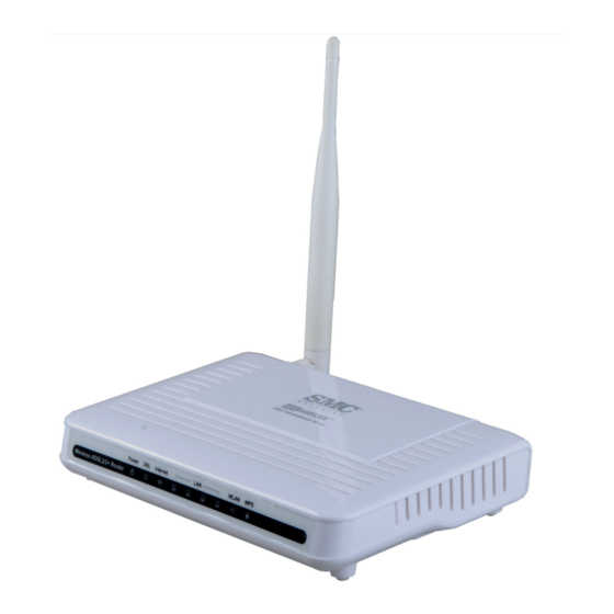
NTRODUCTION The Barricade ADSL Gateway Router (SMC7904WBRAS-N2 v2) is an ADSL2/2+ modem contained in a compact unit. The router enables multiple wired and wireless users to securely access the Internet through a single-user account with the ADSL service provider. The router provides four 10/100 Mbps Ethernet ports for connection to end users, an IEEE 802.11b/g/n wireless interface, and one ADSL line for connection to the... -
Page 27: Description Of Hardware
| Introduction HAPTER Description of Hardware ESCRIPTION OF ARDWARE This ADSL Gateway Router is a high bit-rate Digital Subscriber Line (DSL) modem that can connect to an ADSL Internet service provider. This unit provides the following ports on the rear panel: One RJ-11 port for connection to your ADSL service provider’s incoming ◆... -
Page 28: Figure 2: Rear Panel
| Introduction HAPTER Description of Hardware Figure 2: Rear Panel WLAN On/Off WPS Button Ethernet Ports Power Socket and WAN Port On/Off Switch Reset Button Figure 3: Front Panel LEDs The ADSL Gateway Router includes key system and port indicators that simplify installation and network troubleshooting. -
Page 29: Power Connector
| Introduction HAPTER Description of Hardware Table 1: LED Display Indicators (Continued) Status Description On Green Ethernet port has a valid link with attached device. (1-4) Blinking Green Data is being transmitted or received on the port. Ethernet port has no link with an attached device. WLAN On Green The Wi-Fi radio is enabled. -
Page 30: Installing The Router
ACKAGE ONTENTS After unpacking the ADSL Gateway Router, check the contents of the box to be sure that you have received the following components: Barricade ADSL Gateway Router, SMC7904WBRAS-N2 v2 ◆ ◆ RJ-45 Category 5 network cable RJ-11 telephone cable ◆... -
Page 31: Cable Connections
| Installing the Router HAPTER Cable Connections Power requirements: 12 VDC using the included AC power adapter. ◆ Make sure that a properly grounded power outlet is within 1.8 m (6 ft) of the router. ◆ The router should be located in a cool dry place, with at least 5 cm (2 in.) of space on all sides for ventilation. -
Page 32: Powering On
| Installing the Router HAPTER Powering On The Phone port on the ADSL splitter can be connected to a standard telephone set using telephone cable. Connect one end of the included Ethernet cable to an Ethernet port on the ADSL Gateway Router, and the other end to a PC’s RJ-45 network port. - Page 33 | Installing the Router HAPTER Configuring the TCP/IP Protocols Select “TCP/IP” from the list of network protocols; this may include details of adapters installed in your computer. Click “Properties.” Check the option “Obtain an IP Address.” 2000 INDOWS Click “Start/Settings/Network/Dial-up Connections.” Click “Local Area Connections.”...
- Page 34 | Installing the Router HAPTER Configuring the TCP/IP Protocols If “Using DHCP Server” is already selected in the “Configure” field, your computer is already configured for DHCP. Otherwise, select “Using DHCP Server” in the “Configure” field and close the window. Another box will appear asking whether you want to save your TCP/IP settings.
-
Page 35: Ection
ECTION ONFIGURATION This section describes the basic settings required to access the web management interface and provides details on configuring the Gateway. This section includes these chapters: ◆ “System Configuration” on page 36 “Device Information” on page 45 ◆ “WLAN Configuration” on page 54 ◆... -
Page 36: System Configuration
YSTEM ONFIGURATION SING THE NTERFACE The router provides a web-based management interface for configuring device features and viewing statistics to monitor network activity. This interface can be accessed by any computer on the network using a standard web browser (such as Internet Explorer 5.0, Netscape 6.2, Mozilla Firefox 2.0, or above). -
Page 37: Home Page
| System Configuration HAPTER Using the Web Interface It is strongly recommended to change the default password the first time you access the web interface. For information on changing the password, see “Password Setup” on page 135. When your web browser connects with the router’s web agent, the home page is displayed as shown below. - Page 38 | System Configuration HAPTER Using the Web Interface Table 2: Configuration Menu (Continued) Menu Description Page Statistics Shows the network traffic statistics DSL Statistics Shows the ADSL line statistics Shows entries in the ARP table Wireless Basic Settings Configures basic wireless settings Advanced Settings Configures advanced wireless settings Security...
- Page 39 | System Configuration HAPTER Using the Web Interface Table 2: Configuration Menu (Continued) Menu Description Page FTP ALG Configures FTP server and client ports Configuration NAT IP Mapping Configures IP address mapping for NAT IP QoS Configures IP-based QoS settings MAC Filtering Configures MAC address filtering Configures DMZ settings...
-
Page 40: Setup Wizard
| System Configuration HAPTER Setup Wizard ETUP IZARD The Wizard is designed to help you configure the basic settings required to get the ADSL Gateway Router up and running. Click “Wizard” in the main menu to get started. After reading the wizard welcome message, click Next to continue. 1 - G ETTING TARTED... -
Page 41: Step 3 - Adsl Settings
| System Configuration HAPTER Setup Wizard Server IP – Specifies the IP address of a public NTP time server on the ◆ Internet. Interval – Specifies the time interval for polling the NTP server. ◆ Time Zone – A drop-down box provides access to predefined time ◆... - Page 42 | System Configuration HAPTER Setup Wizard 1483 MER : DHCP — 1483 MER is an RFC standard MAC ■ Encapsulated Routing protocol. 1483 MER : Static IP — 1483 MER is an RFC standard MAC ■ Encapsulated Routing protocol. 1483 Bridged — The Bridged RFC 1483 Encapsulated Traffic over ■...
-
Page 43: Step 4 - Wireless Settings
| System Configuration HAPTER Setup Wizard The fourth page of the wizard configures wireless settings for the ADSL 4 - W IRELESS router. ETTINGS Figure 10: Wizard Step 4 - Wireless Settings The following items are displayed on the first page of the Wizard: WLAN Interface —... -
Page 44: Step 4 - Configuration Saving
| System Configuration HAPTER Setup Wizard WPA2(TKIP/AES): WPA2 using either a static pre-shared key, or ■ 802.1X authentication through a RADIUS server. The encryption used is either TKIP or AES. WPA2 Mixed: WPA and WPA2 using either a static pre-shared key, ■... -
Page 45: Device Information
EVICE NFORMATION The Status pages display information on hardware/software versions, LAN and WAN connection status, statistics, and the ARP table. YSTEM TATUS The System Status page displays the hardware and software versions, and the WAN connection status and speed. Click Status, System. Figure 12: System Status The following items are displayed on this page: YSTEM... -
Page 46: Lan Status
| Device Information HAPTER LAN Status Upstream Speed – The current upload speed of the DSL connection. ◆ Downstream Speed – The current download speed of the DSL ◆ connection. LAN S TATUS The ADSL Router LAN window displays basic LAN port settings including DHCP information. -
Page 47: Wlan Status
| Device Information HAPTER WLAN Status Expiry(s) — Displays the duration of the lease time. ◆ Type — Indicates if the entry is dynamic or static. ◆ WLAN S TATUS The WLAN Status window displays basic wireless interface settings. Figure 14: Status - WLAN The following items are displayed on this page: Wireless Configuration —... -
Page 48: Wan Status
| Device Information HAPTER WAN Status WAN S TATUS The ADSL Router WAN window displays basic IPv4 and IPv6 WAN port settings. Figure 15: Status - WAN The following items are displayed on this page: Interface — Displays the interface identifier. ◆... -
Page 49: Port Mapping
| Device Information HAPTER Port Mapping APPING The Port Mapping status shows the mapping of WAN and LAN interfaces to specific groups. Figure 16: Status - Port Mapping The following items are displayed on this page: Status — Indicates if port mapping is enabled or disabled. ◆... -
Page 50: Traffic Statistics
| Device Information HAPTER Traffic Statistics RAFFIC TATISTICS The ADSL Router Traffic Statistics - Interfaces window displays received and transmitted packet statistics for all interfaces on the ADSL Router. Figure 17: Status - Traffic Statistics The following items are displayed on this page: Interface —... -
Page 51: Dsl Statistics
| Device Information HAPTER DSL Statistics DSL S TATISTICS The ADSL Router DSL Statistics window displays received and transmitted packet statistics for all interfaces on the ADSL Router. Figure 18: Status - DSL Statistics The following items are displayed on this page: ADSL Status —... -
Page 52: Arp Table
| Device Information HAPTER ARP Table SNR Margin Downstream/Upstream (db) — Displays the current ◆ signal-to-noise margin expressed in decibels (dB). SNR is the ratio of signal power to the noise power corrupting the signal. ◆ Vendor ID – The vendor name of the digital signal processor (DSP). DSP Version –... - Page 53 | Device Information HAPTER ARP Table The following items are displayed on this page: IP Address — IP address of a local entry in the cache. ◆ ◆ MAC Address — MAC address mapped to the corresponding IP address. Refresh — Sends a request to update the current parameters. ◆...
-
Page 54: Wlan Configuration
WLAN C ONFIGURATION This chapter describes wireless configuration on the ADSL Router. The unit contains an onboard IEEE 802.11b/g/n access point (AP), which provides wireless data communications between the router and wireless devices. WLAN Configuration contains the following sections: “WLAN Basic Settings” on page 55 ◆... -
Page 55: Wlan Basic Settings
WDS transparent bridging between APs. (Default: AP+WDS) ◆ SSID — The service set identifyer for the access point. (Default: SMC) ◆ Channel Width — The router provides a channel bandwidth of 40 MHz by default giving an 802.11g connection speed of 108 Mbps (sometimes referred to as Turbo Mode) and a 802.11n connection... - Page 56 | WLAN Configuration HAPTER WLAN Basic Settings Mbps respectively and ensures backward compliance for slower 802.11b devices. (Default: 40MHz) Control Sideband — Specifies if the extension channel should be in ◆ the Upper or Lower sideband. When a 40MHz channel bandwidth has been set, the extension channel option will be enabled in the upper or lower sideband.
-
Page 57: Advanced Settings
| WLAN Configuration HAPTER Advanced Settings DVANCED ETTINGS The advanced radio configuration settings are described in the page that follows. Figure 21: Wireless Security Setup - Advanced Settings The following items are displayed on this page: Authentication Type — Sets the basic authentication method. ◆... - Page 58 | WLAN Configuration HAPTER Advanced Settings maintain contact with the ADSL Router. They may also carry power- management information. (Range: 20-1000 TUs; Default: 100 TUs) DTIM Interval — The rate at which stations in sleep mode must wake ◆ up to receive broadcast/multicast transmissions. Known also as the Delivery Traffic Indication Map (DTIM) interval, it indicates how often the MAC layer forwards broadcast/multicast traffic, which is necessary to wake up stations that are using Power Save...
-
Page 59: Wireless Security Setup
| WLAN Configuration HAPTER Wireless Security Setup IRELESS ECURITY ETUP Describes the wireless security settings for each VAP, including association mode, encryption, and authentication. Figure 22: Wireless Security Setup - None The following items are displayed all pages of the Wireless Security Setup: OMMON IRELESS ARAMETERS... -
Page 60: Wep Security
| WLAN Configuration HAPTER Wireless Security Setup and PSK modes of operation. TKIP or AES is used as the multicast encryption cipher. WPA2(Mixed): Clients using WPA or WPA2 are accepted for ■ authentication. TKIP or AES is used as the multicast encryption cipher. -
Page 61: Figure 25: Wireless Security Setup - Wep Key Setup
| WLAN Configuration HAPTER Wireless Security Setup The following items are displayed on this page: Set WEP Key — Configures the WEP key setup. This is displayed in the ◆ screen below. Use 802.1x Authentication — Enables/disables 802.1x ◆ authentication. When enabled the above screen displays. WEP 64bits/128bits —... -
Page 62: Wpa Security
| WLAN Configuration HAPTER Wireless Security Setup Authentication Type — Selects the authentication type to use. ◆ Options are: Open System: If you don’t set up any other security mechanism ■ on the access point, the network has no protection and is open to all users. - Page 63 | WLAN Configuration HAPTER Wireless Security Setup WPA Authentication Mode — Selects between modes of WPA ◆ authentication. Options are: Enterprise: Uses a RADIUS server for authentication. This applies ■ to enterprise deployment. Personal: Uses a pre-shared key for authentication. ■...
-
Page 64: Access Control
| WLAN Configuration HAPTER Access Control CCESS ONTROL Access control configures ACLs (access control lists) which allow or deny wireless traffic based on the sender’s MAC address. Figure 27: Wireless Security Setup - Wireless Access Control The following items are displayed on this page: Wireless Access Control Mode —... -
Page 65: Wi-Fi Protected Setup (Wps)
| WLAN Configuration HAPTER Wi-Fi Protected Setup (WPS) (WPS) ROTECTED ETUP Wi-Fi Protected Setup (WPS) is designed to ease installation and activation of security features in wireless networks. WPS has two basic modes of operation, Push-button Configuration (PBC) and Personal Identification Number (PIN). -
Page 66: Mbssid
| WLAN Configuration HAPTER MBSSID Reset — Resets the WPS settings to factory default values. ◆ Client PIN Number — Enters a PIN number of a wireless client device ◆ that needs to join the network. Click “Start PIN” to activate the WPS process. -
Page 67: Figure 29: Second Bssid
| WLAN Configuration HAPTER MBSSID Figure 29: Second BSSID The following items are displayed on this page: Enable (VAP0-VAP3) — Enables up to four VAP interfaces on the ◆ router. (Default: Disabled) SSID — Configures the service set identifier of a VAP on the wireless ◆... -
Page 68: Wds
| WLAN Configuration HAPTER Broadcast SSID — Enables/disables the wireless interface to ◆ broadcast an SSID (service set identifier) to uniquely identify it on the network. ◆ Relay Blocking — Blocks traffic between SSID interfaces. Authentication Type — Sets the basic authentication method for the ◆... -
Page 69: Figure 31: Wds Wireless Setup
| WLAN Configuration HAPTER Figure 31: WDS Wireless Setup The MAC addresses on all connected routers must be set. Change the LAN address on routers so as to avoid an IP conflict. Figure 32: LAN Basic Setup – 69 –... -
Page 70: Figure 33: Disabling Dhcp
| WLAN Configuration HAPTER DIsable the DHCP server. Figure 33: Disabling DHCP – 70 –... - Page 71 | WLAN Configuration HAPTER – 71 –...
-
Page 72: Lan Settings
LAN S ETTINGS This chapter describes LAN configuration on the ADSL Router. You can use the web browser interface to access IP addressing only if the ADSL Router already has an IP address that is reachable through your network. “LAN Interface” on page 73 ◆... -
Page 73: Lan Interface
| LAN Settings HAPTER LAN Interface LAN I NTERFACE By default, the ADSL Router is configured with the IP address 192.168.2.1, subnet mask 255.255.255.0 and a default gateway of 192.168.2.1. Figure 34: LAN Configuration The following items are displayed on this page: Interface Name —... -
Page 74: Ipv6 Lan Configuration
| LAN Settings HAPTER IPv6 LAN Configuration LAN Port — Selects the LAN port. ◆ Link Speed/Duplex Mode — Selects the port speed and duplex ◆ mode, or sets the port for auto-negotiation. MAC Address Control — Filters out traffic with source MAC addresses ◆... - Page 75 | LAN Settings HAPTER IPv6 LAN Configuration The following items are displayed on this page: RA S ETTING Enable — Enables IPv6 router advertisements on the router. ◆ ◆ M Flag — Sets the router advertisement “Managed address configuration" flag. When set, the router will use DHCPv6 to obtain stateful addresses.
-
Page 76: Dhcp Settings
| LAN Settings HAPTER DHCP Settings portion is automatically generated using the modified EUI-64 form of the client identifier (that is, the client MAC address). IPv6 Address Pool — The address range available for DHCPv6 ◆ assignment. Prefix Length — The length of the IPv6 address prefix sent in DHCPv6 ◆... -
Page 77: Dhcp Relay
| LAN Settings HAPTER DHCP Settings Dynamic Host Configuration Protocol (DHCP) can dynamically allocate an DHCP R ELAY IP address and other configuration information to network clients that broadcast a request. To receive the broadcast request, the DHCP server would normally have to be on the same subnet as the client. However, when the access point’s DHCP relay agent is enabled, received client requests can be forwarded directly by the access point to a known DHCP server on another subnet. -
Page 78: Dhcp Server
| LAN Settings HAPTER DHCP Settings The unit can support up to 253 local clients. Addresses are assigned to DHCP S ERVER clients from a common address pool configured on the unit. Configure an address pool by specifying start and end IP addresses. Be sure not to include the unit's IP address in the address pool range. -
Page 79: Figure 39: Device Ip Range Table
| LAN Settings HAPTER DHCP Settings MAX Lease Time — Select a time limit for the use of an IP address ◆ from the IP pool. When the time limit expires, the client has to request a new IP address. The lease time is expressed in seconds. (Default: 86400 seconds;... -
Page 80: Dhcp Static Ip
| LAN Settings HAPTER DHCP Settings Assigns a physical MAC address to the DHCP pool by mapping it to a DHCP S TATIC corresponding IP address. Figure 40: DHCP Static IP Assignment The following items are displayed on this page: IP Address —... -
Page 81: Wan Settings
WAN S ETTINGS This chapter describes WAN configuration on the ADSL Router. The WAN pages are used to configure standard WAN services, including VPI, VCI, encapsulation, service type (PPPoE, IPoE, bridging), ATM settings and ADSL settings. It includes the following sections: “Channel Configuration”... -
Page 82: Channel Configuration
| WAN Settings HAPTER Channel Configuration HANNEL ONFIGURATION The Channel Configuration page configures channel operation modes of the ADSL Router. Figure 41: WAN Configuration The following items are displayed on this page: Default Route Selection – Enables the default route to be specified or ◆... - Page 83 | WAN Settings HAPTER Channel Configuration VC/MUX (Virtual Circuit Multiplexing) – When using this mode, the ■ communicating hosts agree on the high-level protocol for a given circuit, which tends to reduce fragmentation overhead. This allows a sender to pass each datagram directly to AAL5 for transfer, and requires nothing to be sent besides the datagram and the AAL5 trailer.
-
Page 84: Atm Settings
| WAN Settings HAPTER ATM Settings selected, the WAN interface IP address is assigned by the remote DHCP server. Local IP address — The IP address of the WAN interface provided ■ by the ISP. Gateway — The IP address of the remote gateway router provided ■... - Page 85 | WAN Settings HAPTER ATM Settings VCI (Virtual Channel Identifier) — Adds a VCI entry to the table. ◆ (Range: 32-65535; Default: 35) QoS — Selects packet level Quality of Service (QoS) for the connection. ◆ Options are: UBR (Unspecified Bitrate): Configures a PVC with a Peak Cell Rate ■...
-
Page 86: Adsl Settings
| WAN Settings HAPTER ADSL Settings ADSL S ETTINGS The ADSL Settings page configures the ADSL modulation type, ADSL2+ related parameters, capabilities and the ADSL tone mask. Figure 43: ATM Settings The following items can be enabled on this page: ADSL Modulation —... - Page 87 | WAN Settings HAPTER ADSL Settings ADSL2 — This standard extends the capability of basic ADSL data ■ rates to 12 Mbit/s downstream and 3 Mbit/s upstream (with a mandatory capability of ADSL2 transceivers of 8 Mbit/s downstream and 800 Kbit/s upstream. ADSL2+ —...
-
Page 88: Services
ERVICES The Advanced Configuration settings for the ADSL Router contain advanced system management configuration settings such as DNS setup, routing configuration, bridging, SNMP and TR-069 settings. The following sections are contained in this chapter: “DNS Settings” on page 89 ◆ “Access Control Lists”... -
Page 89: Dns Settings
| Services HAPTER DNS Settings DNS S ETTINGS Sets Domain Name Server (DNS) and Dynamic DNS settings. The Domain Name Server (DNS) implements a human recognizable web DNS S ERVER address to a numerical IP address. DNS can be set automatically or manually. -
Page 90: Ddns
| Services HAPTER DNS Settings The following items are displayed on this page: Obtain DNS Automatically — The DNS server IPv6 address is ◆ automatically configured during dynamic IP assignment. Set DNS Manually — Allows the user to set up to three DNS server ◆... - Page 91 | Services HAPTER DNS Settings Enable — Enables DDNS. (Default: Enabled) ◆ ETTINGS The following parameters apply to the default DynDns setting. User Name — Specifies your username for the DDNS service. ◆ Password — Specifies your password for the DDNs service. ◆...
-
Page 92: Access Control Lists
| Services HAPTER Access Control Lists CCESS ONTROL ISTS The ADSL Router supports Access Control Lists that filter IP addresses allowed access on the unit's LAN and WAN interfaces. Only traffic from IP addresses in the ACL table are allow access to the ADSL Router. When you select LAN for the ACL “direction,”... -
Page 93: Wan Acls
| Services HAPTER Access Control Lists ACL T URRENT ABLE Lists the configured ACLs on the LAN ports. ◆ Select — The number of the entry in the table. Direction — Displays if the ACL is applied to a LAN or WAN interface. ◆... - Page 94 | Services HAPTER Access Control Lists Add — Adds the ACL to the ACL Table. ◆ ACL T URRENT ABLE Lists the configured ACLs on the LAN ports. Select — The number of the entry in the table. ◆ Direction — Displays if the ACL is applied to a LAN or WAN interface. ◆...
-
Page 95: Ip/Port Filtering
| Services HAPTER IP/Port Filtering IP/P ILTERING IP/Port filtering restricts connection parameters to limit the risk of intrusion and defends against a wide array of common hacker attacks. IP/Port filtering allows the unit to permit, deny or proxy traffic through its ports and IP addresses. - Page 96 | Services HAPTER IP/Port Filtering Source IP Address — Specifies the source IP address to block or allow ◆ traffic from. Destination IP Address — Specifies the destination IP address to ◆ block or allow traffic from. Subnet Mask — Specifies a subnet mask. ◆...
-
Page 97: Nat/Napt Settings
| Services HAPTER NAT/NAPT Settings NAT/NAPT S ETTINGS Network Address Translation (NAT) is a standard method of mapping multiple “internal” IP addresses to one “external” IP address on devices at the edge of a network. For the router, the internal (local) IP addresses are the IP addresses assigned to local PCs by the DHCP server, and the external IP address is the IP address assigned to the specified WAN interface. -
Page 98: Figure 50: Nat - Virtual Servers
| Services HAPTER NAT/NAPT Settings Figure 50: NAT — Virtual Servers The following items are displayed on this page: Service Type – Sets a name to describe the virtual server service. ◆ Usual Service Name – Select a name from the list of common ■... -
Page 99: Nat Exclude Ip
| Services HAPTER NAT/NAPT Settings You can use the Exclude IP feature to block an IP address or range of IP NAT E XCLUDE addresses from accessing WAN interfaces. Figure 51: NAT — Exclude IP The following items are displayed on this page: Interface –... -
Page 100: Nat Alg And Pass-Through
| Services HAPTER NAT/NAPT Settings Remote IP Address — Specifies the source IP address on the WAN to ◆ allow access from. Leaving this parameter blank allows access from all traffic. ◆ Enable — Checking this box activates the parameters configurated once added to the Current NAT Port Forwarding Table. -
Page 101: Nat Port Trigger
| Services HAPTER NAT/NAPT Settings MSN — Enables MSN passthrough. (Default: Enabled) ◆ Port triggering is a way to automate port forwarding in which outbound NAT P RIGGER traffic on predetermined ports (“triggering ports”) causes inbound traffic to specific incoming ports to be dynamically forwarded to the initiating host while the outbound ports are in use. -
Page 102: Ftp Alg Configuration
| Services HAPTER NAT/NAPT Settings FTP ALG Configuration specifies a non-standard FTP port for passthrough FTP ALG traffic. The standard port for FTP connections is TCP port 21, and the router ONFIGURATION monitors port 21 to ensure the NAT passthrough of FTP. When the FTP server port is not 21, you must specify the TCP port to ensure NAT passthrough of FTP. -
Page 103: Quality Of Service
| Services HAPTER Quality of Service The following items are displayed on this page: Type – Selects the type of mapping to use. Either one-to-one, one-to- ◆ many, many-to-many, or many-to-one. Local Start/End IP – Defines a local IP address pool range. ◆... - Page 104 | Services HAPTER Quality of Service The following items are displayed on this page: IP QoS – If enabled, QoS rules will be applied to traffic entering the ◆ Gateway. QoS Policy – Selects Stream-based, 802.1p-based, or DSCP-based ◆ policy. Schedule Mode –...
-
Page 105: Mac Filtering
| Services HAPTER MAC Filtering MAC F ILTERING MAC based packet filtering enables the router to filter clients based on their physical layer address. Figure 58: MAC Filtering Settings The following items are displayed on this page: Outgoing Default Policy — A default action for MAC addresses not ◆... -
Page 106: Dmz
| Services HAPTER DMZ enables a specified host PC on the local network to access the Internet without any firewall protection. Some Internet applications, such as interactive games or videoconferencing, may not function properly behind the router's firewall. By specifying a Demilitarized Zone (DMZ) host, the PC's TCP ports are completely exposed to the Internet, allowing open two-way communication. -
Page 107: Url Blocking
| Services HAPTER URL Blocking URL B LOCKING By filtering inbound Uniform Resource Locators (URLs) the risk of compromising the network can be reduced. URLs are commonly used to point to websites. By specifying a URL or a keyword contained in a URL traffic from that site may be blocked. -
Page 108: Software Forbidden
| Services HAPTER Software Forbidden OFTWARE ORBIDDEN The Software Forbidden page enables traffic from listed application software to be blocked by the router. Figure 61: Software Forbidden Settings The following items are displayed on this page: Current Forbidden Software List — Software applications that are ◆... -
Page 109: Dos
| Services HAPTER Denial of Service (DoS) is an attempt by a hacker to flood an IP address, domain, or server with repeated external communincation requests, effectively saturating the system with an information flood that renders it slow or effectively inoperable for genuine users to access it. DoS attacks are also referred to as non-intrusion attacks, the goal of which is to cripple your system but not steal data. - Page 110 | Services HAPTER Whole System Flood: FIN: Prevents a FIN (no more data from ■ sender) flood in which part of a TCP packet from an invalid (or spoofed) IP address floods the network with connection resets. Whole System Flood: UDP: Prevents a flood of large numbers of ■...
-
Page 111: Igmp Proxy Configuration
| Services HAPTER IGMP Proxy Configuration TCP SynWithData: Prevents the hacker sending a volume of ■ requests for connections that cannot be completed. UDP Bomb: Also called a UDP Flood or packet storm. Prevents the ■ hacker congesting the network by generating a flood of UDP packets between it and the unit using the UDP chargen service (a testing utility that generates a character string for every packet it receives). -
Page 112: Figure 63: Igmp Proxy Configuration
| Services HAPTER IGMP Proxy Configuration Figure 63: IGMP Proxy Configuration The following items are displayed on this pages: IGMP Proxy — Enables IGMP proxy. When enabled, the upstream ◆ interface acts as a host interface, sending query messages periodically to the downstream interfaces, sending join and leave messages to the upstream multicast router when a first join or last leave message is received from a downstream interface, and sending membership... -
Page 113: Rip Configuration
| Services HAPTER RIP Configuration RIP C ONFIGURATION RIP is an Internet protocol you can set up to share routing table information with other routing devices on your LAN, at your ISP’s location, or on remote networks connected to your network via the ADSL line. Most small home or office networks do not need to use RIP;... -
Page 114: Arp Binding Configuration
| Services HAPTER ARP Binding Configuration ARP B INDING ONFIGURATION The router uses its tables to make routing decisions, and uses Address Resolution Protocol (ARP) to forward traffic from one hop to the next. ARP is used to map an IP address to a physical layer MAC address. When an IP frame is received by the router, it first looks up the MAC address corresponding to the destination IP address in the ARP cache. -
Page 115: Advanced
DVANCED The Advanced Configuration settings for the ADSL Router contain advanced system management configuration settings. The following sections are contained in this chapter: “Bridge Setting” on page 116 ◆ “Log Setting” on page 117 ◆ “Routing Configuration” on page 118 ◆... -
Page 116: Bridge Setting
| Advanced HAPTER Bridge Setting RIDGE ETTING This feature allows you to set the bridge aging time and to enable Spanning Tree. The Spanning Tree Protocol (STP) can be used to detect and disable network loops, and to provide backup links between bridges. This allows a wireless bridge to interact with other bridging devices (that is, an STP- compliant switch, bridge or router) in your network to ensure that only one route exists between any two stations on the network, and provide backup... -
Page 117: Log Setting
| Advanced HAPTER Log Setting ETTING The ADSL Router supports a logging process that controls error messages saved to memory. The logged messages serve as a valuable tool for isolating ADSL Router and network problems. The Log Setting page displays the latest messages logged in chronological order. -
Page 118: Routing Configuration
| Advanced HAPTER Routing Configuration VENT ABLE Displays the current entries in the System Log table. ◆ Time — Displays the date and time the log entry was created. Index — The number of the log entry. ◆ Type — Displays the source of the log message. ◆... - Page 119 | Advanced HAPTER Routing Configuration Subnet Mask — The network mask of the destination subnet. The ◆ default gateway uses a mask of 0.0.0.0. Next Hop — The IP address of the next hop through which traffic will ◆ flow towards the destination subnet. Metric —...
-
Page 120: Upnp
| Advanced HAPTER UPnP UPnP (Universal Plug and Play) provides inter-connectivity between devices supported by the same standard. UPnP is based on standard Internet protocols, such as TCP/IP, UDP, and HTTP. Figure 69: UPnP The following items are displayed on this page: UPnP —... -
Page 121: Snmp Protocol Configuration
| Advanced HAPTER SNMP Protocol Configuration SNMP P ROTOCOL ONFIGURATION Simple Network Management Protocol (SNMP) is a communication protocol designed specifically for managing devices on a network. SNMP is typically used to configure devices for proper operation in a network environment, as well as to monitor them to evaluate performance or detect potential problems. -
Page 122: System Time Configuration
| Advanced HAPTER System Time Configuration YSTEM ONFIGURATION The System Time page allows you to manually configure time settings or enable the use of an NTP server. Figure 71: System Time Configuration The following items are displayed on this page: System Time —... -
Page 123: Other Advanced Configuration
| Advanced HAPTER Other Advanced Configuration THER DVANCED ONFIGURATION Enables the Half Bridge feature for PPPoE (PPPoA) connections. When the router is set to Half Bridge, it establishes the PPPoE/PPPoA connection with the ISP, then forwards all other traffic to DHCP clients connected to the router. -
Page 124: Port Mapping
| Advanced HAPTER Port Mapping APPING Port Mapping supports multiple ports to WAN interfaces and bridging groups. Each group performs as an independent network. You can create up to four groups on the router. Figure 73: Port Mapping Configuration The following items are displayed on this page: WAN –... -
Page 125: Diagnostics
IAGNOSTICS The Diagnostics page is used to test the local Ethernet connection, or the WAN connection for the DSL signal and the connection to DSL provider network. This chapter contains the following sections: “Diagnostic Test” on page 126 ◆ “Ping” on page 127 ◆... -
Page 126: Diagnostic Test
| Diagnostics HAPTER Diagnostic Test IAGNOSTIC The diagnostic test shows the test results for the connectivity of the physical layer and protocol layer for both LAN and WAN sides. Figure 74: Diagnostic Test The following items are displayed on this page: Select the Interface —... -
Page 127: Ping
| Diagnostics HAPTER Ping The ADSL Router provides the function of “pinging” its own IP address or URL to test for connectivity. Figure 75: Ping The following items are displayed on this page: Host — The host IP address or URL to test for connectivity. ◆... -
Page 128: Traceroute
| Diagnostics HAPTER Traceroute RACEROUTE Traceroute discovers the routes that packets take when traveling to a destination. Traceroute works by taking advantage of the error messages generated by routers when a packet exceeds its time-to-live (TTL) value. The traceroute command first sends probe datagrams with the TTL value set at one. -
Page 129: Figure 79: Traceroute Result
| Diagnostics HAPTER Traceroute Figure 79: Traceroute Result – 129 –... -
Page 130: Adsl Tone Diagnostics
| Diagnostics HAPTER ADSL Tone Diagnostics ADSL T IAGNOSTICS The ADSL page displays diagnostic testing for the ADSL connection. Figure 80: ADSL Tone Diagnostics The following items are displayed on this page: Start — Starts the diagnostics test. ◆ Downstream/Upstream — Displays downstream and upstream ◆... - Page 131 | Diagnostics HAPTER ADSL Tone Diagnostics Output Power (dBm) — Displays the output power of the unit in ◆ decibels per milliwatt. Tone Number — Displays the tone number of the ADSL signal. ◆ (Range: 0~255) H.Real — Displays the real part of channel transfer function of each ◆...
-
Page 132: Administration Settings
DMINISTRATION ETTINGS The Admin pages are used to manage configuration files, system logs, TR- 069 ACS, passwords; and also to update software and reboot the system. This chapter contains the following sections: “Commit/Reboot” on page 133 ◆ “Backup/Restore Settings” on page 134 ◆... -
Page 133: Commit/Reboot
| Administration Settings HAPTER Commit/Reboot OMMIT EBOOT Use this page to save the current configuration and reboot the system. Figure 81: Commit/Reboot The following items are displayed on this page: Reboot from — Select the option for router’s configuration: ◆ Save the current configuration —... -
Page 134: Backup/Restore Settings
| Administration Settings HAPTER Backup/Restore Settings ACKUP ESTORE ETTINGS The Backup/Restore Settings page allows you to backup current settings to a local file, and load previously saved settings to the unit. Figure 83: Backup/Restore Settings The following items are displayed on this page: ◆... -
Page 135: Password Setup
| Administration Settings HAPTER Password Setup ASSWORD ETUP Management access to the ADSL Router is controlled through different levels of user name and password. To protect access to the management interface, you need to configure a new Administrator’s password as soon as possible. If a new password is not configured, then anyone having access to the ADSL Router may be able to compromise the unit's security by entering the default values. -
Page 136: Upgrade Firmware
| Administration Settings HAPTER Upgrade Firmware PGRADE IRMWARE You can update the ADSL Router’s firmware by using the Upgrade Firmware facility which allows you to upload new firmware manually by specifying a file path. Make sure the firmware file you want to use is on the local computer by clicking Browse to search for the file to be used for the update. -
Page 137: Configuration
| Administration Settings HAPTER TR-069 Configuration TR-069 C ONFIGURATION The Technical Report 069 (TR069) protocol defines a specification for remote management of CPE devices. The protocol uses HTTP for two-way communication between the CPE device and an Auto Configuration Server (ACS), allowing service providers to provide CPE configuration, software upgrades, and other service functions for end-users. - Page 138 | Administration Settings HAPTER TR-069 Configuration The following items are displayed on this pages: Defines the Auto Configuration Server parameters. Enable — Enables/disables TR-069 support. (Default: Enabled) ◆ URL — Speceifies the URL required for the CPE to connect to the ACS. ◆...
- Page 139 | Administration Settings HAPTER TR-069 Configuration Skip MReboot — Specifies whether to send an MReboot event code in ◆ the inform message. Delay — Specifies whether to start TR-069 after a short delay. ◆ Auto-Execution — Specifies whether to automatically start TR-069 ◆...
-
Page 140: Ection
ECTION PPENDICES This section provides additional information and includes these items: “Troubleshooting” on page 141 ◆ “Hardware Specifications” on page 143 ◆ “Cables and Pinouts” on page 147 ◆ – 140 –... -
Page 141: A Troubleshooting
ROUBLESHOOTING IAGNOSING ATEWAY NDICATORS Gateway operation is easily monitored via the LED indicators to identify problems. The table below describes common problems you may encounter and possible solutions. If the solutions in the table fail to resolve the problem, contact technical support for advice. Table 3: LED Troubleshooting Chart Symptom Cause... -
Page 142: If You Cannot Connect To The Internet
| Troubleshooting PPENDIX If You Cannot Connect to the Internet ANNOT ONNECT TO THE NTERNET Check that your computer is properly configured for TCP/IP. For more ◆ information, see “Configuring the TCP/IP Protocols” on page Make sure the correct network adapter driver is installed for your PC ◆... -
Page 143: Specifications
ARDWARE PECIFICATIONS HYSICAL HARACTERISTICS 1 RJ-11 DSL line (to phone jack in the wall) ORTS 4 RJ-45 10/100BASE-TX (Ethernet connection to PC) RJ-45 connector, auto MDI/X pinout detection THERNET NTERFACE 10BASE-T: 100-ohm, UTP cable; Category 3 or better 100BASE-TX: 100-ohm, UTP cable; Category 5 or better *Maximum Cable Length - 100 m (328 ft) RJ-11 connector, using standard phone cable (26 AWG) DSL I... -
Page 144: Wireless Characteristics
| Hardware Specifications PPENDIX Wireless Characteristics IRELESS HARACTERISTICS 2.4 ~ 2.484 GHz REQUENCY 11b: 11/5.5/2/1M (Automatic) ADIO 11g: 54/48/36/24/18/12/9/6M (Automatic) 11n: HT40 up to 150 Mbps, HT20 up to 65 Mbps (Automatic) Up to 14 (depending on region) HANNELS 802.11b: 64-QAM, 16-QAM, QPSK, BPSK, DSSS ODULATION 802.11g: CCK, DQPSK, DBPSK 802.11n, HT20 and HT40: 64-QAM, 16-QAM, QPSK, BPSK... - Page 145 | Hardware Specifications PPENDIX Software Features Ethernet bridging RIDGE EATURES Support for transparent bridging - MAC address learning - MAC address filtering and protocol filtering for up-link RIP v1/v2 OUTING EATURES Static routing PPP/PPPoE (RFC 2516) NAT with ALGs NAPT IGMP v1/v2 IGMP proxy and snooping IPv4...
-
Page 146: Standards
| Hardware Specifications PPENDIX Standards 802.1p bit remarking Traffic classification by port, 802.1p , ToS, and DSCP TANDARDS IEEE 802.3-2005 Ethernet Access THERNET TANDARDS Ethernet, Fast Ethernet Full-duplex flow control (ISO/IEC 8802-3) IEEE 802.1D Spanning Tree Protocol IEEE 802.1p priority tags 802.11b IRELESS TANDARDS... -
Page 147: Ables And Pinouts
ABLES AND INOUTS WISTED ABLE SSIGNMENTS For 10/100BASE-TX connections, a twisted-pair cable must have two pairs of wires. For 1000BASE-T connections the twisted-pair cable must have four pairs of wires. Each wire pair is identified by two different colors. For example, one wire might be green and the other, green with white stripes. -
Page 148: 10/100Base-Tx Pin Assignments
| Cables and Pinouts PPENDIX 10/100BASE-TX Pin Assignments 10/100BASE-TX P SSIGNMENTS Use unshielded twisted-pair (UTP) or shielded twisted-pair (STP) cable for RJ-45 connections: 100-ohm Category 3 or better cable for 10 Mbps connections. Also be sure that the length of any twisted-pair connection does not exceed 100 meters (328 feet). -
Page 149: Crossover Wiring
| Cables and Pinouts PPENDIX Crossover Wiring ROSSOVER IRING If the twisted-pair cable is to join two ports and either both ports are labeled with an “X” (MDI-X) or neither port is labeled with an “X” (MDI), a crossover must be implemented in the wiring. (When auto-negotiation is enabled for any RJ-45 port on this gateway, you can use either straight- through or crossover cable to connect to any device type.) Figure 89: Crossover Wiring... -
Page 150: Port
| Cables and Pinouts PPENDIX RJ-11 Port RJ-11 P Standard telephone RJ-11 connectors and cabling can be found in several common wiring patterns. These six-pin connectors can accommodate up to three wire-pairs (three telephone lines), but usually only one or two pairs of conductor pins and wires are implemented. - Page 151 LOSSARY IEEE 802.3-2005 specification for 10 Mbps Ethernet over two pairs of 10BASE-T Category 3 or better UTP cable. IEEE 802.3-2005 specification for 100 Mbps Fast Ethernet over two pairs of 100BASE-TX Category 5 or better UTP cable. IEEE 802.3ab specification for 1000 Mbps Gigabit Ethernet over four pairs 1000BASE-T of Category 5 or better UTP cable.
- Page 152 LOSSARY International Telecommunication Union Telecommunication Standardization Section of ITU ITU-T Local Area Network: A group of interconnected computers and support devices. The physical layer address used to uniquely identify network nodes. MAC A DDRESS Maximum Transfer Unit. The maximum transfer unit for traffic crossing this device.
- Page 153 LOSSARY A connector for twisted-pair wiring. RJ-45 C ONNECTOR A filter to separate DSL signals from POTS signals to prevent mutual PLITTER interference. Simple Network Time Protocol: SNTP allows a device to set its internal SNTP clock based on periodic updates from a Network Time Protocol (NTP) server.
- Page 154 NDEX UMERICS 10/100BASE-TX pin assignments Ethernet 100BASE-TX 10BASE-T factory defaults, resetting front panel access control ACLs ADSL capability ADSL modulation Gateway ADSL settings features ADSL tone diagnostics guard interval advanced settings AnnexL option AnnexM option ARP table hardware, description ATM settings HT channel bandwidth backup/restore settings IGMP proxy configuration...
- Page 155 NDEX port RJ-11 WAN status RJ-45 Web interface port indicators access requirements power adapter, details home page power connector wireless security setup powering on common wireless parameters problems, troubleshooting WEP security WLAN basic settings WPA security WPS security rear panel Reset button RIP configuration RJ-11...
- Page 156 Taiwan 30077 Tel: +886 3 5770270 From U.S.A. and Canada (24 hours a day, 7 days a week) Tel: +1 (800) SMC-4-YOU/+1 (949) 679-8000 Fax: +1 (949) 679-1481 Fax: +886 3 5780764 Asia-Pacific Office (for Asia-Pacific): Technical Support information at www.smc-asia.com 1 Coleman Street (for Middle East): Technical Support information at muneer@smc-asia.com...
Need help?
Do you have a question about the SMC7904WBRAS-N2 V2 and is the answer not in the manual?
Questions and answers