Table of Contents
Advertisement
Quick Links
User Guide | EVAL-ADIS16501
UG-2240
ADIS16501-2/PCBZ MEMS IMU Breakout Board
OVERVIEW
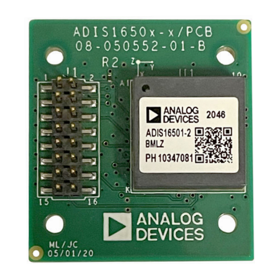
EVALUATION BOARD PHOTOGRAPH
The ADIS16501-2/PCBZ breakout board offers a simple method for
developing a prototype connection between the
ADIS16501
inertial
measurement unit (IMU) and any existing embedded processor
platform that supports serial peripheral interface (SPI) communi-
cations. The ADIS16501-2/PCBZ comes pre-equipped with the
ADIS16501 IMU and a 16-pin header that is designed to connect
seamlessly with 2 mm ribbon cables. Generally, this board supports
reliable communication over ribbon cables up to 20 cm in length.
However, for optimal performance, especially when dealing with
critical communication links, it is recommended to validate the
signal integrity before entirely relying on this type of connection.
Figure 1. ADIS16501-2/PCBZ IMU Top View
PLEASE SEE THE LAST PAGE FOR AN IMPORTANT
Rev. 0 | 1 of 15
WARNING AND LEGAL TERMS AND CONDITIONS.
Advertisement
Table of Contents

Related Manuals for Analog Devices ADIS16501-2/PCBZ


Summary of Contents for Analog Devices ADIS16501-2/PCBZ
-
Page 1: Overview
User Guide | EVAL-ADIS16501 UG-2240 ADIS16501-2/PCBZ MEMS IMU Breakout Board OVERVIEW EVALUATION BOARD PHOTOGRAPH The ADIS16501-2/PCBZ breakout board offers a simple method for developing a prototype connection between the ADIS16501 inertial measurement unit (IMU) and any existing embedded processor platform that supports serial peripheral interface (SPI) communi- cations. -
Page 2: Table Of Contents
Guide Objective and Scope........3 EVAL-ADIS-FX3 System Setup and Versions of the ADIS16501-2/PCBZ Troubleshooting..........8 Breakout Board..........3 ADIS16501-2/PCBZ Data Acquisition ....9 Compatible Systems and Processor ADIS16501-2/PCBZ Integration Example... 10 Platforms............3 Dimensions and Mounting Holes......11 Evaluation Systems Compatibility...... 3 Electrical Schematic and J1 Connector Pin Handling and Inspecting ........ -
Page 3: Introduction
VERSIONS OF THE ADIS16501-2/PCBZ technology supported by Analog Devices. BREAKOUT BOARD The ADIS16501-2/PCBZ breakout board is part of a family of products designed to facilitate the development of prototype con- nections between microelectric mechanical system (MEMS) IMUs and embedded processor platforms. This guide specifically covers... -
Page 4: Handling And Inspecting
Follow these instructions for unpacking and inspecting the ADIS16501-2/PCBZ breakout board: Take the following steps to inspect the ADIS16501-2/PCBZ break- out board and the contents of the shipping container: Before opening the shipping container, inspect it for any signs of ►... -
Page 5: Adis16501-2/Pcbz Breakout Board Components
Data ready SYNC Synchronization input Figure 3. ADIS16501-2/PCBZ Components Do not connect The ADIS16501 IMU is central to the ADIS16501-2/PCBZ break- Do not connect out board (see Figure 4). This high performance, multi-axis IMU provides accurate angular rate (gyroscope) and linear acceleration (accelerometer) measurements. -
Page 6: Ribbon Cable Connection Between The Adis16501 And Eval-Adis-Fx3
USB Connector It provides a dual role for both programming the It can be used to upload firmware updates for debugging microcontroller and powering the ADIS16501-2/PCBZ purposes through a direct connection to a PC. when connected to a USB host device. - Page 7 Component Description Function Usage Recommendations Microcontroller (or Processing Unit) It acts as the brain of the ADIS16501-2/PCBZ, It is programmed to customize its operation for specific processing all data from the IMU and managing applications under recommended conditions. communications with other connected devices.
-
Page 8: Cabling
It is recommended to use 2.00 mm IDC ribbon cable assembly as search criteria to find the latest options on the market. At the time of initial release for the ADIS16501-2/PCBZ breakout board, Analog Devices used the Samtec TCSD-10-S-01.00-01-N. EVAL-ADIS-FX3 SYSTEM SETUP AND... -
Page 9: Adis16501-2/Pcbz Data Acquisition
Direct access to the ADIS16501 IMU via the J1 connector (see ► Figure Data acquisition and transfer. The ADIS16501-2/PCBZ breakout ► board utilizes the microcontroller or processing unit (see Number 6 in Figure 5) to manage the flow of data from the ADIS16501... -
Page 10: Adis16501-2/Pcbz Integration Example
Used for stabilization, navigation, and motion control, provid- ► ing essential data for precise movements and balance. The ADIS16501-2/PCBZ processes the IMU data to determine ► orientation and movement, which is crucial for tasks such as balancing or navigating uneven terrain in robotic systems. -
Page 11: Dimensions And Mounting Holes
User Guide EVAL-ADIS16501 DIMENSIONS AND MOUNTING HOLES The ADIS16501-2/PCBZ breakout board has four mounting holes (one in each corner) that support attachment to another surface with M2 machine screws (see Figure Figure 7. Dimensions and Mounting Holes analog.com Rev. 0 | 11 of 15... -
Page 12: Electrical Schematic And J1 Connector Pin Configuration
J1 connector, and Figure 9 illustrates the electrical schematic for the ADIS16501-2/ PCBZ. Figure 8. Pin Configuration for J1 Connector Figure 9. Electrical Schematic for the ADIS16501-2/PCBZ analog.com Rev. 0 | 12 of 15... -
Page 13: Reference Designs For Working With The Adis16501-2/Pcbz
User Guide EVAL-ADIS16501 REFERENCE DESIGNS FOR WORKING WITH THE ADIS16501-2/PCBZ The following reference designs are provided for users ready to evaluate the ADIS16501. These designs include the following com- ponents: Physical connection ► Details on the physical connection between the ADIS16501-2/ ►... -
Page 14: Part Number Summary
IMU model number that is the board. Table 3. Available Breakout Board Model Measurement Range Breakout Board Gyroscope Accelerometer ADIS16501-2/PCBZ ADIS16501-2BMLZ ±500 DPS ±14 g analog.com Rev. 0 | 14 of 15... - Page 15 Evaluation Board until you have read and agreed to the Agreement. Your use of the Evaluation Board shall signify your acceptance of the Agreement. This Agreement is made by and between you (“Customer”) and Analog Devices, Inc. (“ADI”), with its principal place of business at Subject to the terms and conditions of the Agreement, ADI hereby grants to Customer a free, limited, personal, temporary, non-exclusive, non-sublicensable, non-transferable license to use the Evaluation Board FOR EVALUATION PURPOSES ONLY.
Need help?
Do you have a question about the ADIS16501-2/PCBZ and is the answer not in the manual?
Questions and answers