
Subscribe to Our Youtube Channel
Related Manuals for Analog Devices ADZS-AD2428MINI


Summary of Contents for Analog Devices ADZS-AD2428MINI
- Page 1 ADZS-AD2428MINI Manual Revision 1.0 , October 2019 Part Number 82-AD2428MINI-01 Analog Devices, Inc. One Technology Way Norwood, MA 02062-9106...
- Page 2 Analog Devices, Inc. reserves the right to change this product without prior notice. Information furnished by Ana- log Devices is believed to be accurate and reliable. However, no responsibility is assumed by Analog Devices for its use; nor for any infringement of patents or other rights of third parties which may result from its use. No license is granted by implication or otherwise under the patent rights of Analog Devices, Inc.
-
Page 3: Table Of Contents
Manual Contents ............................1–1 Technical Support ............................1–2 Supported Integrated Circuit ......................... 1–2 Supported Tools............................. 1–2 Product Information ............................1–2 Analog Devices Website..........................1–2 EngineerZone ............................. 1–2 Using the Board Product Overview ............................2–1 Package Contents............................2–1 Default Configuration ........................... 2–2 Reference Design Information ........................ - Page 4 I2C Address( P4 )............................3–7 Local Power Mode() ........................... 3–8 Bus Power Mode() ............................3–8 LEDs ................................3–8 A2B IO1 & IO7 LED ( DS3 and DS1 ) ..................... 3–9 B Interrupt ( DS2 )..........................3–9 ADZS-AD2428MINI Manual...
-
Page 5: Preface
DSP code writing experience to easily implement a DSP into their design and yet is still powerful enough to satisfy the demands of experienced DSP designers. SigmaStudio links with both Analog Devices evalua- tion boards and production designs to provide full in-circuit real-time IC control. -
Page 6: Technical Support
If you are a registered user, just log on. Your user name is your e-mail address. EngineerZone EngineerZone is a technical support forum from Analog Devices, Inc. It allows you direct access to ADI technical support engineers. You can search FAQs and technical information to get quick answers to your embedded process- ing and DSP design questions. -
Page 7: Using The Board
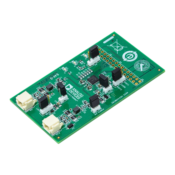
Your ADZS-AD2428MINI package contains the following items. • ADZS-AD2428MINI board • DuraClik 1.8M cable • A2B Software - Online Request Document Contact the vendor where you purchased your ADZS-AD2428MINI evaluation board or contact Analog Devices, Inc. if any item is missing. ADZS-AD2428MINI Manual 2–1... -
Page 8: Default Configuration
Figure 2-1: Default Hardware Setup Reference Design Information A reference design info package is available for download on the Analog Devices Web site. The package provides information on the schematic design, layout, fabrication, and assembly of the board. The information can be found at: https://my.analog.com/en/myanalog/a2b/a2b-technology.html... -
Page 9: Ad2428 - Automotive Audio Bus A 2 B Transceiver
The PG flag signals when V is within ±9% of the programmed output voltage as well as fault conditions. The LT8620 is available in small 16-Lead MSOP and 3mm × 5mm QFN packages with exposed pads for low thermal resistance. ADZS-AD2428MINI Manual 2–3... -
Page 10: Hardware Reference
Hardware Reference 3 Hardware Reference This chapter describes the hardware design of the ADZS-AD2428MINI . System Architecture The board's configuration is shown in the Block Diagram figure. ADZS-AD2428MINI Manual 3–1... -
Page 11: Connectors
EEPROM Duraclick Port B LT8620 Breakout 0.1" Header High Speed Connector Figure 3-1: Block Diagram Connectors This section describes connector functionality and provides information about mating connectors. The connector locations are shown in the Connector Locations figure. 3–2 ADZS-AD2428MINI Manual... -
Page 12: A 2 B ( P10 And P9 )
A2B Interface( P1 ) The A B Interface is a high speed connection that allows connecting the ADZS-AD2428MINI to other boards, such as the ADZS-EZKIT-SOM. This connector brings out the signals for I2S, TWI, SPI, GPIO, 1.8v power, 3.3v power, VBUS and also is +12v input for the ADZS-AD2428MINI. - Page 13 35 36 37 38 SIO7 39 40 41 42 43 44 45 46 47 48 48 50 51 52 53 54 ~RESET 55 56 57 58 59 60 61 62 SPI_MISO 63 64 65 66 SPI_MOSI 67 68 3–4 ADZS-AD2428MINI Manual...
-
Page 14: A2B Breakout Header( P2 )
ADZS-EZKIT-SOM. This connector brings out the signals for I2S, TWI, GPIO, 1.8v power, 3.3v pow- er, VBUS and also is +12v input for the ADZS-AD2428MINI. It can also be used for probing or wiring in other evauluation boards or custom designs. -
Page 15: Jumpers
29 30 GND I2C_SDA 31 32 VBAT_IN Part Description Manufacturer Part Number A2B Breakout Header SAMTEC TSW-116-08-G-D Mating Connector SSQ-116-01-G-D Jumpers This section describes functionality of the configuration jumpers. The Jumper Locations figure shows the jumper locations. 3–6 ADZS-AD2428MINI Manual... -
Page 16: Iovdd( P3 )
Figure 3-3: Jumpers IOVDD( P3 ) The AD2428 supports 1.8v and 3.3v logic on the IO signals. On the ADZS-AD2428MINI board, the IOVDD voltages are supplied from the internal regulators on the AD2428 Transceiver. To set the IOVDD of the AD2428, set the jumper according to the table below: Jumper Voltage Configuration 1.8v... -
Page 17: Local Power Mode()
Local Power Mode() The ADZS-AD2428MINI supports multiple modes of the AD2428. Local Power Mode is used for when configur- ing the AD2428 as a Master node or as a Local Power Slave. In Local Power Mode, 12V is supplied to the LT8620 switching supply from P1 or P2 and it bucked down to 8.5V. -
Page 18: A2B Io1 & Io7 Led ( Ds3 And Ds1 )
Figure 3-4: LED Locations A2B IO1 & IO7 LED ( DS3 and DS1 ) The A B IO1 and IO7 signals are connected to LEDs on the ADZS-AD2428MINI. Refer to the HRM for further info on using interrupts. B Interrupt ( DS2 ) The A B interrupt LED is driven by the AD2428 (add link). - Page 19 ADZS-AD2428MINI Manual...
Need help?
Do you have a question about the ADZS-AD2428MINI and is the answer not in the manual?
Questions and answers