Table of Contents
Advertisement
Quick Links
One Technology Way • P.O. Box 9106 • Norwood, MA 02062-9106, U.S.A. • Tel: 781.329.4700 • Fax: 781.461.3113 • www.analog.com
Evaluating the
ADIS16500, ADIS16505,
FEATURES OF EVAL-ADIS2
Simple power connection using the USB 5 V connection and
on-board switching and LDO voltage regulators
Regulators easily bypassed for power measurements
On-board ADSP-BF527 DSP
Easy access to digital I/O and diagnostic signals via I/O
header
Status LEDs for diagnostic signals
Windows-based GUI with data logging, complete access to
register map, and real-time updating of accelerometer and
gyroscope outputs
APPLICATIONS
Performance evaluation of IMU
Small size permits mounting onto test fixtures or inside of
autonomous vehicle
PLEASE SEE THE LAST PAGE FOR AN IMPORTANT
WARNING AND LEGAL TERMS AND CONDITIONS.
Using the EVAL-ADIS2 Evaluation Platform
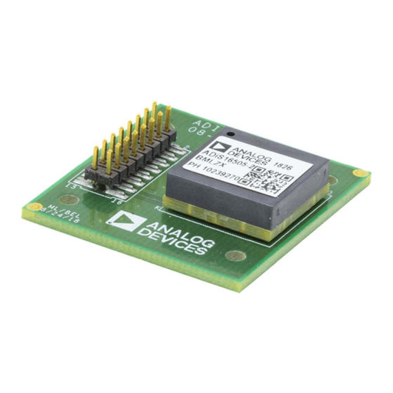
Figure 1.
ADIS16505-2
Rev. PR.C | Page 1 of 11
ADIS1650x
and
ADIS16507
Inertial Measurement Units
GENERAL DESCRIPTION
This user guide applies to the ADIS1650x IMU (Inertial
Measurement Units). The members of this family include the
ADIS16500, ADIS16505, and
ADIS16505
is discussed within, this guide is applicable to all
members of the ADIS1650x family, as these devices differ
primarily performance levels and sensitivity ratings.
The
ADIS16505
is a very small, high-performance. The
ADIS16505
features factory internal calibration, high
performance, and robust operation in dynamic and challenging
environments.
The
ADIS16505
evaluation board, together with the
ADIS2
are a compact, easy-to-use platform for evaluating all
features of the ADIS16505.
Evaluation Board
/PCBZ User Guide
UG-ADIS1650x
ADIS16507. Although only the
EVAL-
Advertisement
Table of Contents

Related Manuals for Analog Devices ADIS1650 Series


Summary of Contents for Analog Devices ADIS1650 Series
-
Page 1: Features Of Eval-Adis2
ADIS1650x /PCBZ User Guide UG-ADIS1650x One Technology Way • P.O. Box 9106 • Norwood, MA 02062-9106, U.S.A. • Tel: 781.329.4700 • Fax: 781.461.3113 • www.analog.com Evaluating the ADIS16500, ADIS16505, ADIS16507 Inertial Measurement Units Using the EVAL-ADIS2 Evaluation Platform FEATURES OF EVAL-ADIS2 GENERAL DESCRIPTION Simple power connection using the USB 5 V connection and This user guide applies to the ADIS1650x IMU (Inertial... -
Page 2: Table Of Contents
UG-ADIS1650x ADIS1650x/PCBZ User Guide TABLE OF CONTENTS Features of EVAL-ADIS2 ..............1 USB Driver Installation ..............5 Applications ..................1 Downloading the Evaluation Software ........6 General Description ................. 1 EVAL-ADIS2 Physical Connections ...........7 Revision History ................ -
Page 3: The Adis165505 Breakout Board
ADIS1650x/PCBZ User Guide UG-ADIS1650x THE ADIS165505 BREAKOUT BOARD Figure 2. ADIS16505-2/PCBZ DRAWING DESCRIPTION Figure 3 provides a top-level view of the breakout board layout, Breakout boards provide a simple way to connect an existing along with key physical attributes. The electrical interface (J1) embedded processor platform to an ADIS16500, ADIS16505 or on each breakout board is a dual row, 2 mm pitch, 16-pin ADIS16507 IMU. -
Page 4: Pin Assignments
UG-ADIS1650x ADIS1650x/PCBZ User Guide PIN ASSIGNMENTS Table 2. J1 Pin Assignments, Breakout Board Table 2 provides the J1 pin assignments which support direct J1 Pin Number Signal Function connection to an embedded processor board using standard Reset ribbon cables. Although each environment has its own SCLK sensitivities (such as electromagnetic interference (EMI)), these boards typically support reliable communication over ribbon... -
Page 5: Evaluation Using The Eval-Adis2 System
ADIS1650x/PCBZ User Guide UG-ADIS1650x EVALUATION USING THE EVAL-ADIS2 SYSTEM Figure 5. EVAL-ADIS2 System Block Diagram In addition to supporting quick prototype connections between the IMU and an embedded processing system, the breakout boards connect directly to J1 on the EVAL-ADIS2 evaluation system. -
Page 6: Changes To Evaluation Software Hyperlink
UG-ADIS1650x ADIS1650x/PCBZ User Guide Click on Install to continue with the installation if this message appears during the process: Click Finish to complete the process. DOWNLOADING THE EVALUATION SOFTWARE The evaluation software for the ADIS16505 can be downloaded from the ADI IMU ftp site Navigate to the ftp site by clicking here: ftp://ftp.analog.com/pub/IMU/IMU_FTP_Directory.htm Click on “IMU Evaluation 1.18.xx”... -
Page 7: Eval-Adis2 Physical Connections
ADIS1650x/PCBZ User Guide UG-ADIS1650x EVAL-ADIS2 PHYSICAL CONNECTIONS Figure 8 illustrates the physical connection between the ADIS16505-2/PCBZ and an EVAL-ADIS2Z evaluation system. Connecting the Evaluation Boards Ensure that Jumper JP1 (See “DUT Supply Selection” in Figure 6) is straddling the left “+3.3V REG” pin and the center pin, assuming the EVAL-ADIS2 board is oriented as shown in Figure 6. -
Page 8: Evaluation Software
UG-ADIS1650x ADIS1650x/PCBZ User Guide EVALUATION SOFTWARE On the Devices Menu, select the correct IMU model. RUNNING THE EVALUATION SOFTWARE Ensure the that USB Driver is properly installed as described in the “USB Driver Installation” section of this user’s guide. Ensure that the evaluation board is properly connected as described in the “EVAL-ADIS2 Physical Connections”... - Page 9 ADIS1650x/PCBZ User Guide UG-ADIS1650x Movement of the IMU is recorded and displayed in real Logging the IMU readings is a common task using the time: EVAL-ADIS2 and clicking on the Data Capture menu brings up the data capture window. This window allows the user to choose which settings to log.
-
Page 10: Troubleshooting
ADIS1650x/PCBZ User Guide UG-ADIS1650x TROUBLESHOOTING RUNNING THE SOFTWARE WITHOUT AN EVAL- ADIS2 EVALUATION BOARD ATTACHED The user will see the following screens if the evaluation software is run without the EVAL-ADIS2 connected: In this case, the user should exit out of the software, and proceed to the “EVAL-ADIS2 Physical Connections”... - Page 11 By using the evaluation board discussed herein (together with any tools, components documentation or support materials, the “Evaluation Board”), you are agreeing to be bound by the terms and conditions set forth below (“Agreement”) unless you have purchased the Evaluation Board, in which case the Analog Devices Standard Terms and Conditions of Sale shall govern. Do not use the Evaluation Board until you have read and agreed to the Agreement.
Need help?
Do you have a question about the ADIS1650 Series and is the answer not in the manual?
Questions and answers