Sign In
Upload
Download
Table of Contents
Contents
Add to my manuals
Delete from my manuals
Share
URL of this page:
HTML Link:
Bookmark this page
Add
Manual will be automatically added to "My Manuals"
Print this page
×
Bookmark added
×
Added to my manuals
Manuals
Brands
Field Controls Manuals
Fan
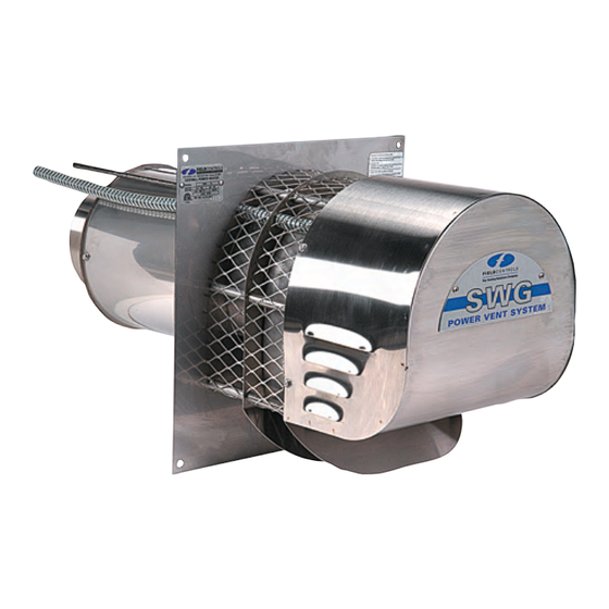
SWG-3
Product manual
Field Controls SWG-3 Product Manual
Hide thumbs
Also See for SWG-3
:
Brochure & specs
(14 pages)
,
Manual
(12 pages)
1
Table Of Contents
2
3
4
5
6
7
8
9
10
11
12
13
14
15
16
17
18
19
20
21
22
23
24
25
26
27
28
29
30
31
32
33
34
35
36
37
38
39
40
41
42
43
44
45
46
47
48
49
50
51
52
53
54
55
56
57
58
59
60
61
62
page
of
62
Go
/
62
Contents
Table of Contents
Bookmarks
Table of Contents
Table of Contents
SWG/CV Power Venter
Combovent™ (CV)
Power Venter Sizing & Installation
Planning the Vent System
Clearance to Combustibles
Control Kits
System Setup & Maintenance
System Setup and Maintenance
Annual Maintenance
Ventriser
PV Power Venters
SWG Vent Kits
Vent Hoods
Vent Caps
Electrical Specifications
Gas Vent Damper
Oil Vent Damper
How It Works
Thermal Safety Switches
Combustion Air Systems
Make-Up Air System
Draft Control
Installation Options
Draft Control Installation & Sizing
Choosing the Right Size
Draft Inducers
Open Hearth
Automatic Flue Dampers for Gas Fireplaces
How It Works
Automatic Flue Dampers Sizing & Selection
Chimney Top Draft Inducer
Chimney Fan with Damper
Hearth Combustion Air
Replacement Parts
Advertisement
Quick Links
Download this manual
2024
COMBUSTION PRODUCTS GUIDE
Table of
Contents
Previous
Page
Next
Page
1
2
3
4
5
Advertisement
Table of Contents
Need help?
Do you have a question about the SWG-3 and is the answer not in the manual?
Ask a question
Questions and answers
Related Manuals for Field Controls SWG-3
Fan Field Controls Oil Venting Systems Brochure & Specs
Venting for oil applications (14 pages)
Fan Field Controls SWG Stainless Series Manual
(12 pages)
Boiler Supplies Field Controls SWGII-5 Manual
Sidewall power venter kit (20 pages)
Fan FIELD CONTROLS 46256400 Manual
Sidewall power venter kit for commercial water heaters (16 pages)
Automobile Parts Field Controls SWG-4HD Instruction Manual
Repair motor kit (4 pages)
Accessories FIELD CONTROLS 46252300 Instruction Sheet
Repair motor kit (4 pages)
Engine Field Controls SWG-4HD Quick Start Manual
(4 pages)
Fan FIELD CONTROLS 46334200 Instruction Sheet
Swg sidewall power venting kit (20 pages)
Fan FIELD CONTROLS 46139100 Instructions Manual
Sidewall power venter kit (12 pages)
Fan FIELD CONTROLS 4592700 Instructions
Field type barometric draft controls wood and oil burning installation (4 pages)
Fan FIELD CONTROLS 46229000 Manual
Sidewall power venter kit (12 pages)
Fan FIELD CONTROLS 46263300 Manual
Starkap chimney cap (12 pages)
Fan FIELD CONTROLS 46334800 Manual
Sidewall power venting system (12 pages)
Fan FIELD CONTROLS 46413900 Manual
Sidewall power venter kit (12 pages)
Fan Field Controls SWG-4HDs Product Manual
(62 pages)
Fan Field Controls SWG-AF Series Installation Manual
Sidewall power vent (37 pages)
This manual is also suitable for:
Swg-4hd
Swg-4hds
Swg-5
Swg-5s
Swg-6
Swg-6s
...
Show all
Swg-8
Cv-4
Cv-5
Table of Contents
Print
Rename the bookmark
Delete bookmark?
Delete from my manuals?
Login
Sign In
OR
Sign in with Facebook
Sign in with Google
Upload manual
Upload from disk
Upload from URL


Need help?
Do you have a question about the SWG-3 and is the answer not in the manual?
Questions and answers