Table of Contents
Advertisement
Quick Links
TYPICAL VENTING SYSTEM COMPONENTS:
PART
NUMBER
SWGII-5 POWER VENTER,
239-81764-00
CK-41 24 VOLT CONTROL KIT
SWGII-5 POWER VENTER,
239-81765-00
CK-81 MILLIVOLT CONTROL KIT
SWGII-6 POWER VENTER,
239-81766-00
CK-41 24 VOLT CONTROL KIT
SWGII-6 POWER VENTER,
239-81767-00
CK-81 MILLIVOLT CONTROL KIT
SWG-8 POWER VENTER,
239-82148-00
CK-41 24 VOLT CONTROL KIT
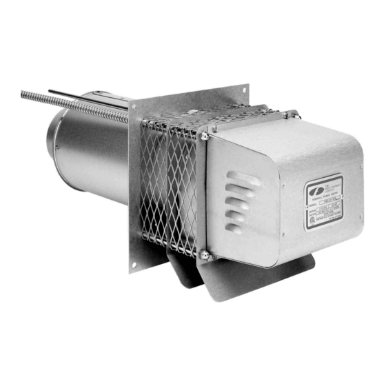
SIDEWALL POWER VENTER KIT
Model: SWGII-5,6 AGA and SWG-8*
FOR COMMERCIAL WATER HEATERS
DESCRIPTION
THESE INSTRUCTIONS MUST REMAIN WITH EQUIPMENT
*Patented
COMMERCIAL WATER HEATERS WITH 24 VOLT
CONTROLS WITH INPUT RATINGS OF UP TO 290,000
COMMERCIAL WATER HEATERS WITH MILLIVOLT
CONTROLS WITH INPUT RATINGS OF UP TO 290,000
COMMERCIAL WATER HEATERS WITH 24 VOLT
CONTROLS WITH INPUT RATINGS GREATER THAN
290,000 BTU/HR. UP TO 416,000 BTU/HR.
COMMERCIAL WATER HEATERS WITH 24 VOLT
CONTROLS WITH INPUT RATINGS GREATER THAN
290,000 BTU/HR. UP TO 416,000 BTU/HR.
COMMERCIAL WATER HEATERS WITH 24 VOLT
CONTROLS WITH INPUT RATINGS GREATER THAN
DO NOT DESTROY
APPLICATION
BTU/HR.
BTU/HR.
415,000 BTU/HR.
Advertisement
Table of Contents

Related Manuals for Field Controls 46256400


Summary of Contents for Field Controls 46256400
- Page 1 SIDEWALL POWER VENTER KIT Model: SWGII-5,6 AGA and SWG-8* FOR COMMERCIAL WATER HEATERS *Patented TYPICAL VENTING SYSTEM COMPONENTS: PART DESCRIPTION APPLICATION NUMBER COMMERCIAL WATER HEATERS WITH 24 VOLT SWGII-5 POWER VENTER, 239-81764-00 CONTROLS WITH INPUT RATINGS OF UP TO 290,000 CK-41 24 VOLT CONTROL KIT BTU/HR.
-
Page 2: Installation Safety Instructions
CONTROL KITS 1. For 24 volt control systems (intermittent pilot ignition): CK-41 control kit with the following components: Junction box with mounted pressure switch and relay base, 24 volt relay for controlling power venter motor, 1 ft. length of 0.25" aluminum tubing, 0.25"... - Page 3 2. Safety inspection of a venting system should be performed before and after installing a power venting system on an existing or new appliance. Procedures to follow are those recommended by the National Fuel Gas Code, A.N.S.I.Z223.1, or refer to General Installation Inspection section of this manual. 3.
- Page 4 ROCEDURE FOR CALCULATING TOTAL EQUIVALENT PIPE LENGTH IN FEET 1. Calculate the total equivalent feet for each type of fitting used in the venting system from the chart below. 2. Calculate the total amount of feet for the straight lengths of vent pipe. 3.
-
Page 5: Connecting Power Venter To Appliance
Figure 3 Figure 4 Diagram A 3. After determining the location of the venting system termination point (See Diagram A), cut a square hole through the wall 1" larger than the outer pipe diameter of the power venter. Mount the power venter through the wall, keeping the outer pipe centered in the hole. - Page 6 If mounting venting system near combustible materials, refer to Diagram B for allowable installation clearances. Clearances are based on an installation using single wall galvanized steel vent pipe. For metal thickness of galvanized steel pipe connectors, refer to NFPA 211 or NFPA 54 Standards for guidelines. If manufactured double wall vent pipe is required or used for the installation, clearance should be based on the vent pipes rated clearance.
-
Page 7: Wiring Instructions
CLASS B AND CLASS L DOUBLE WALL VENT PIPE INSTALLATION (Follow vent pipe manufacturer's listed or recommended clearances from combus- tible material.) 5. Using a hand crimper or a like device, crimp the inner pipe of the SWG power venter approximately 1" long. (See Figure 8) 6. - Page 8 Install the GSK-3 spillage switch on the draft hood with the self- tapping sheet metal screw supplied. The thermal element disc should hang just below the draft hood relief opening. (See Figure 10) 8. Run the two (2) yellow wires from the break in the top of the wiring harness into the spillage switch through the plastic bushing opening and connect to the switch terminals.
- Page 9 Figure 11 Page 9...
- Page 10 Figure 12 Page 10...
- Page 11 -81 C ONTROL IRING ILLIVOLT ATER EATER ONTROLS 1. Remove wiring harness from control kit box. 2. Remove top knockout from the thermostat. Push the snap bushing supplied over the knockout hole created to prevent the wires from being chafed. Insert wire harness through bushing hole in thermostat top.
-
Page 12: Pressure Switch Adjustment
PRESSURE SWITCH ADJUSTMENT Important: Both the CK-41 and CK-81 power vent control systems have a pressure switch which must be properly set before the water heater can be started. The pressure switches are set so that the contacts will not close until properly set by the installer. Failure to carefully follow the procedure below for setting the pressure switch will either prevent the water heater from operating properly of defeat the safety feature of the control which could allow a... -
Page 13: Maintenance
Should the motor or blower wheel need replacing, the following replacement items are available. The Repair Motor Assembly contains the Motor and Blower Wheel factory assembled to a mounting bracket. FIELD CONTROLS PART NUMBERS MODEL REPAIR MOTOR KIT... - Page 14 4. Remove the four nuts securing the motor assembly, and pull the motor assembly straight off of the unit. (See Figure 5. Clean off any build-up inside the blower wheel housing and the blower wheel. CAUTION: Avoid applying excess pres- sure on the blower wheel when cleaning off any build-up of material.
- Page 15 INSTALLATION INFORMATION MODEL NO.:_____________________________________________________________ INSTALLER’S NAME: _____________________________________________________ INSTALLER’S COMPANY:__________________________________________________ INSTALLER’S PHONE NO.:_________________________________________________ DATE OF INSTALLATION: _________________________________________________ Page 15...
- Page 16 PN 46256400 Rev B 7/00...
Need help?
Do you have a question about the 46256400 and is the answer not in the manual?
Questions and answers