Advertisement
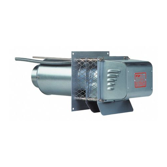
SIDEWALL POWER VENTER KIT
TYPICAL VENTING SYSTEM COMPONENTS
1 - SWG Series Power Venter
1 - CK Series Control Kit (sold separately)
OPTIONAL SYSTEM COMPONENTS
SWG SERIES THROUGH-WALL EXTENSION KIT
For installation in wall thickness over 8 inches. Models PEK-4 through PEK-8 are available.
FOR MOST MULTIPLE HEATING EQUIPMENT SYSTEMS
One CK Series Control Kit for each appliance. Except for a 24V gas furnace or boiler and a 30mV
water heater multiple venting system, use the CK-90 Series Control Kit.
CONTENTS
Available Control Kits ....................................2
Installation Instructions ................................2
Wiring .................................................................7
Air Flow Adjustments ....................................8
GENERAL SYSTEM INFORMATION
Designed for operation with natural gas, LP gas and #2 fuel oil appliances.
1. The thermostat (wall thermostat or aquastat) calls for heat and energizes a relay which activates the
power venter. After the venter motor has come up to speed, the pressure switch closes. This closes the
circuit to the burner and allows the burner to fi re.
2. For millivolt controlled water heaters using the CK-20 Series Control Kit, the gas valve pressure switch
activates the power venter at the same time as the burner fi res.
3. After the heating requirement has been satisfi ed, the thermostat circuit will open and de-activate the
burner and power venter circuit.
4. For venting systems equipped with a post purge device, the power venter operates for a period of time
after the burner has shut off to purge remaining fl ue gases.
READ THESE INSTRUCTIONS CAREFULLY AND COMPLETELY BEFORE PROCEEDING WITH THE INSTALLATION.
This device MUST be installed by a qualifi ed agency in accordance with the manufacturer's installation instructions. The defi nition of
a qualifi ed agency is: any individual, fi rm, corporation or company which either in person or through a representative is engaged
in, and is responsible for, the installation and operation of HVAC appliances, who is experienced in such work, familiar with all the
precautions required, and has complied with all the requirements of the authority having jurisdiction.
Installed By:
Model: SWG & SWG Stainless Series
*Patented
General Inspection ........................ 8
Maintenance .................................... 9
Repair Parts ...................................... 9
System Information .................... 12
Please retain these instructions after installation.
Phone:
www.fi eldcontrols.com
CK series control kit
sold separately
Installation Date:
P/N 46139100 Rev P 08/19
Advertisement

Subscribe to Our Youtube Channel
Related Manuals for Field Controls SWG Stainless Series


Summary of Contents for Field Controls SWG Stainless Series
-
Page 1: Table Of Contents
SIDEWALL POWER VENTER KIT Model: SWG & SWG Stainless Series *Patented CK series control kit TYPICAL VENTING SYSTEM COMPONENTS 1 - SWG Series Power Venter sold separately 1 - CK Series Control Kit (sold separately) OPTIONAL SYSTEM COMPONENTS SWG SERIES THROUGH-WALL EXTENSION KIT For installation in wall thickness over 8 inches. -
Page 2: Available Control Kits
CONTROL KITS CK-20F/HWK: For operation with 30 or 750 millivolt gas-fi red water heaters, gas-fi red space heaters, and gas-fired pool or spa heaters with an internally mounted thermostat. Includes a fixed post purge. CK-40F/41F: For operation with gas-fi red furnaces, boilers, unit heaters and water heaters operating with a 24 VAC gas valve. - Page 3 For gas appliances, use a Field Controls Type MG-1 Barometric Draft Control. For oil appliances, use a Field Controls Type M or RC Barometric Draft Control. Gas-fi red draft induced systems should have a single-acting barometric draft control installed.
- Page 4 Table 2 EQUIVALENT LENGTH (FEET) OF VENT PIPE FITTING VENT PIPE DIAMETER VENT PIPE FITTINGS 3" 4" 5" 6" 7" 8" 9" 10" 90º ELBOW 45º ELBOW ⁄ SUDDEN REDUCER OR INCREASER FOR 3 *RATIOS (d/D) ⁄ ⁄ *Reducer or increaser ratio (d/D) small diameter divided reducer ratio is d/D = ⁄...
- Page 5 SWG SERIES POWER VENTER INSTALLATION LOCATIONS SWG Series Power SWG Series Power Venter Must Be Mounted Venter Must Be At At Least 3 Feet From Least 1 Foot Above Inside Corners. Doors Or Windows. SWG Power Venter Must Be At Least 7 Feet Above Public Walkways.
- Page 6 CONNECTING POWER VENTER TO APPLIANCE Diagram B Venting system should be installed and supported in accordance with the National Fuel Gas Code ANSI Z223.1, or in accordance with any local codes. A vent pipe connector shall be supported for the design and weight of the material employed, to maintain clearances, prevent physical damage and separation of joints.
-
Page 7: Wiring
INSTALLATION USING SINGLE WALL VENT PIPE Table 3 INSTALLATION CLEARANCE WITH SINGLE WALL VENT PIPE DOUBLE PIPE SYSTEM SINGLE PIPE SYSTEM Allowable inlet Allowable inlet Allowable inlet Allowable inlet Clearance Clearance temperature SWG temperature temperature SWG temperature Stainless Steel Stainless Steel 400ºF or less 400ºF or less ⁄... -
Page 8: Air Flow Adjustments
If this occurs, a post purge timer may be required. If so, use a Field Controls PPC-5 Electronic Post Purge or a Control Kit which includes one. Before installing, refer to the General Installation Inspection to check for negative pressure problems in the building. -
Page 9: Maintenance
5. Visually determine that the main burner is burning properly; i.e., no fl oating, lifting or fl ashbacks. When performing smoke test on oil-fi red systems, the burner should operate at a zero to a trace smoke. This can indicate reduced available combustion air to burner. 6. - Page 10 REMOVAL AND INSTALLATION OF THE SWG SERIES POWER VENTER MOTOR ASSEMBLY 1. Remove the screws securing the motor enclosure cover. (See Figure 9) 2. Remove the screws securing the motor assembly. Rotate the motor assembly counterclockwise and slide the assembly into the center. Then pull the motor assembly out of the unit. (See Figure 10) 3.
- Page 11 REMOVAL AND INSTALLATION OF THE SWG SERIES POWER VENTER MOTOR ASSEMBLY Removal 1. Remove the motor enclosure cover by loosening the four screws. (See Figure 9) 2. Open the electrical box on the motor and disconnect the conduit and wires from the motor. (See Figure 13) 3.
-
Page 12: System Information
This manual may be downloaded and printed from the Field Controls website (www.fi eldcontrols.com) This manual may be downloaded and printed from the Field Controls website (www.fi eldcontrols.com) WARRANTY WARRANTY For warranty information about this or any Field Controls product, visit: For warranty information about this or any Field Controls product, visit: www.fi eldcontrols.com/ventCool...
Need help?
Do you have a question about the SWG Stainless Series and is the answer not in the manual?
Questions and answers