Advertisement
Quick Links
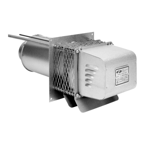
SIDEWALL POWER VENTER KIT
TYPICAL VENTING SYSTEM COMPONENTS
1 - SWG Series Power Venter
1 - CK Series Control Kit
OPTIONAL SYSTEM COMPONENTS
SWG S
T
ERIES
HROUGH
through PEK-8 are available.
F
M
M
H
OR
OST
ULTIPLE
a gas furnace and a water heater multiple venting system, use the CK-90 Series Control Kit.
CONTENTS
Installation Instructions ................................. 2
Air Flow Adjustments .................................... 7
General Installation Inspection ..................... 8
GENERAL SYSTEM OPERATION
Designed for operation with natural or LP gas appliances.
1. The thermostat (wall thermostat, or aquastat) calls for heat and energizes a relay which activates the
power venter. After the venter motor has come up to speed, the pressure switch closes. This closes the
circuit to the burner and allows the burner to operate.
2. For millivolt controlled water heaters, the gas valve pressure switch activates the power venter at the
same time as the burner fires.
3. After the heating requirement has been satisfied, the thermostat circuit will open and de-activate the
burner and power venter circuit.
4. For venting system equipped with a post purge device, the power venter operates for a period of time
after the burner has shut off to purge remaining flue gases.
CONTROL KITS:
CK-41: For operation with gas-fired furnaces, boilers, unit heaters and water heaters operating with 24 VAC
gas valve. For systems with factory-mounted spillage switches, use the CK-40 Control Kit.
CK-43: For draft induced 24 VAC gas valve systems. Includes a 4" MG-1 draft control and electronic post
purge.
CK-81: For operation with 750 millivolt operated boilers, furnaces, water heaters, pool or spa heaters and
gas-fired fireplaces when operating with remote mounted thermostat. Operated off a 24 VAC
thermostat. For operation off of a 120 VAC thermostat or wall switch, use the CK-80.
CK-90: For operation with a gas-fired furnace or boiler and a 30 millivolt water heater.
CK-91: For gas fired draft induced 24 VAC gas valve systems and a 30 millivolt operated water heater.
Includes a 4" MG-1 draft control and an electronic post purge.
Model: SWG II AGA Series
-W
E
K
: For installation in wall thickness over 8 inches. Models PEK-4
ALL
XTENSION
IT
E
S
EATING
QUIPMENT
YSTEMS
DO NOT DESTROY
THESE INSTRUCTIONS MUST REMAIN WITH EQUIPMENT
*Patented
: One CK Series Control Kit for each appliance. Except for
Maintenance ...................................9
Replacement Parts .........................9
System Information.......................10
Advertisement

Subscribe to Our Youtube Channel
Related Manuals for Field Controls 46229000


Summary of Contents for Field Controls 46229000
-
Page 1: Table Of Contents
SIDEWALL POWER VENTER KIT Model: SWG II AGA Series *Patented TYPICAL VENTING SYSTEM COMPONENTS 1 - SWG Series Power Venter 1 - CK Series Control Kit OPTIONAL SYSTEM COMPONENTS SWG S : For installation in wall thickness over 8 inches. Models PEK-4 ERIES HROUGH XTENSION... - Page 2 A gas-fired draft induced system should have a single-acting or double-acting barometric draft control installed, such as the Field Controls Type MG-1. 10. The power venter must be installed downstream of the appliance draft hood or barometric draft control.
- Page 3 INSTALLATION OF SWG POWER VENTER UNIT SIZING CHART MAXIMUM EQUIVALENT FEET OF VENT PIPE MAX* MAX** VENTING WITH OIL GPH BTU/HR. MODEL AT MAX. AT 60% OF MAX. VENT PIPE SIZE INPUT INPUT BTU/HR. INPUT BTU/HR. INPUT 3” SWG-3 70,000 4”...
- Page 4 QUIVALENT ENGTH ITTING VENT PIPE DIAMETER VENT PIPE FITTINGS 3” 4” 5” 6” 7” 8” 9” 10” 90° ELBOW 45° ELBOW SUDDEN REDUCER OR ¼ INCREASER FOR THREE ½ *RATIOS (d/D) ¾ *Reducer or increaser ratio (d/D) small diameter divided by the larger diameter. Example 4"...
- Page 5 Diagram A After determining the location of the venting system termination point (See Diagram A), cut a square hole through the wall 1" larger than the outer pipe diameter of the power venter. Mount the power venter through the wall, keeping the outer pipe centered in the hole.
-
Page 6: Installation Instructions
Diagram B ONNECTING OWER ENTER PPLIANCE This device must be used only with up to two listed gas-fired appliances equipped with draft hoods, draft diverters, or barometric draft controls. Venting system should be installed and supported in accordance with the National Flue Gas Code A.N.S.I.Z223.1, or in accordance with any local codes. -
Page 7: Air Flow Adjustments
Shut off thermostat and check for residual heat spilling from draft hood. If this occurs, a post purge system may be required. If so, use a Field Controls PPC-5 Electronic Post Purge or a Control Kit which includes one. Before installing, refer to the General Installation Inspection to check for negative pressure problems in the building. -
Page 8: General Installation Inspection
GENERAL INSTALLATION INSPECTION Recommended procedures for safety inspection of an appliance in accordance with the National Fuel Gas Code A.N.S.I.Z223.1. The following procedure will help evaluate the venting system. It is intended as a guide to aid in deter- mining that the venting system is properly installed and is in a safe condition for continuous use. This procedure should be recognized as a generalized procedure which cannot anticipate all situations. -
Page 9: Maintenance
MAINTENANCE NOTE: The installer must notify the owner/user of the device of the maintenance requirements listed below. This instruction sheet must also be left with the owner/user. 1. Motor: Inspect the motor once a year - motor should rotate freely. To prolong the life of the motor, it should be lubricated with six drops of SWG Superlube, Part # 46226200, annually. - Page 10 REMOVAL AND INSTALLATION OF THE MOTOR ASSEMBLY EMOVAL 1. Remove the motor enclosure cover by loosening the four screws. (See Figure 2. Open the electrical box on the motor and disconnect the conduit and wires from the motor. (See Figure 11) 3.
- Page 11 Page 11...
- Page 12 PN 46229000 Rev A 08/00...
Need help?
Do you have a question about the 46229000 and is the answer not in the manual?
Questions and answers