Advertisement
Quick Links
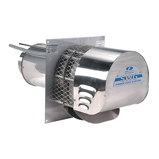
SIDEWALL POWER VENTER KIT
TYPICAL VENTING SYSTEM COMPONENTS
1 - SWG Series Power Venter
1 - Motor Starter Assembly
1 - CK Series Control Kit (sold separately)
F
M
M
H
OR
OST
ULTIPLE
One CK Series Control Kit for each appliance. Except for a 24V gas furnace or boiler and a
30mV water heater multiple venting system, use the CK-90 Series Control Kit.
CONTENTS
Available Control Kits .................................... 2
Installation Instructions .............................. 2-6
Wiring......................................................... 7-8
Air Flow Adjustments .................................... 8
GENERAL SYSTEM INFORMATION
Designed for operation with natural gas, LP gas and #2 fuel oil appliances.
1. The thermostat (wall thermostat or aquastat) calls for heat and energizes a relay which activates
the power venter. After the venter motor has come up to speed, the pressure switch closes. This
closes the circuit to the burner and allows the burner to fire.
2. For millivolt controlled water heaters using the CK-20 Series Control Kit, the gas valve pressure
switch activates the power venter at the same time as the burner fires.
3. After the heating requirement has been satisfied, the thermostat circuit will open and de-activate
the burner and power venter circuit.
4. For venting systems equipped with a post purge device, the power venter operates for a period
of time after the burner has shut off to purge remaining flue gases.
THESE INSTRUCTIONS MUST REMAIN WITH EQUIPMENT
Model: SWG-10, SWG-12, SWG-14
*Patented
E
S
EATING
QUIPMENT
YSTEMS
DO NOT DESTROY
CK series control kit
sold separately
General Inspection ................................... 9
Maintenance ............................................. 9
Replacement Parts ................................. 10
System Information ................................ 11
Advertisement

Related Manuals for Field Controls 46413900


Summary of Contents for Field Controls 46413900
-
Page 1: Table Of Contents
SIDEWALL POWER VENTER KIT Model: SWG-10, SWG-12, SWG-14 *Patented CK series control kit sold separately TYPICAL VENTING SYSTEM COMPONENTS 1 - SWG Series Power Venter 1 - Motor Starter Assembly 1 - CK Series Control Kit (sold separately) ULTIPLE EATING QUIPMENT YSTEMS One CK Series Control Kit for each appliance. -
Page 2: Available Control Kits
For gas appliances, use a Field Controls Type MG-1 Barometric Draft Control. For oil appliances use a Field Controls Type M or RC Barometric Draft Control. Gas-fired draft induced systems should have a single-acting barometric draft control installed. - Page 3 INSTALLATION OF SWG POWER VENTER (See Table 1) Table 1 UNIT SIZING CHART MAXIMUM EQUIVALENT FEET OF VENT PIPE MAX* MAX** AT MAX BTU/HR AT 60% OF MAX VENTING WITH MODEL OIL GPH BTU/HR. INPUT BTU/HR INPUT VENT PIPE SIZE INPUT IMPUT 8”...
- Page 4 ROCEDURE ALCULATING OTAL QUIVALENT ENGTH 1. Calculate the total equivalent feet for each type of fitting used in the venting system from the chart below. 2. Calculate the total amount of feet for the straight lengths of vent pipe. 3. Add the equivalent feet for the fitting with the total amount of feet of straight lengths. This will approximate the total equivalent feet of the vent system.
- Page 5 Diagram A 3. After determining the location of the venting system termination point (see Diagram A), cut a square hole through the wall at least 1" larger than the outer pipe diameter of the power venter. (See Note Below) Mount the power venter through the wall, keeping the outer pipe centered in the hole.
- Page 6 ONNECTING OWER ENTER PPLIANCE Venting system should be installed and supported in accordance with the National Flue Gas Code A.N.S.I.Z223.1, or in accordance with any local codes. A vent pipe connector shall be supported for the design and weight of the material employed, to maintain clearances, prevent physical damage and separation of joints.
-
Page 7: Wiring
Diagram B WIRING NOTE: Wire the power venter motor and controls in accordance with the National Electric Code and applicable local codes. Unit must be grounded. Check ground circuit to make certain that the unit has been properly grounded. The venter power feed wiring should be protected by an over-current circuit device rated at 20 amperes. -
Page 8: Air Flow Adjustments
If this occurs, a post purge timer may be required. If so, use a Field Controls PPC-5 Electronic Post Purge or a Control Kit which includes one. Before installing, refer to the General Installation Inspection to check for negative pressure problems in the building. -
Page 9: General Inspection
GENERAL INSTALLATION INSPECTION Recommended procedures for safety inspection of an appliance in accordance with the National Fuel Gas Code A.N.S.I.Z223.1. The following procedure will help evaluate the venting system. It is intended as a guide to aid in determining that the venting system is properly installed and is in a safe condition for continuous use. This procedure should be recognized as a generalized procedure which cannot anticipate all situations. -
Page 10: Replacement Parts
REPLACEMENT PARTS Should the motor or blower wheel need replacing, the following replacement items are available. The Repair Motor Assembly contains the Motor and Blower Wheel factory assembled to a mounting bracket. PART NUMBERS MODEL REPAIR MOTOR ASSEMBLY BLOWER WHEEL SWG-10 46414001 46408200... -
Page 11: System Information
4. Using an 11/32" nut driver or 1/4" drive deep socket, locate each of the (6) #8- 32 locknuts on their respective mounting studs and torque to 35-40 in-lb. (See Figure 12) Use caution to avoid stripping the threads! 5. Torque the (3) 3/8" nuts to 90-100 in-lbs. Using a large Phillips screwdriver or equivalent inserted through the hole in the cooling fan cover, push the motor shaft inwards while rotating to verify clearance between the blower wheel and body assembly. - Page 12 Page 12 P/N 46413900 09/01...
Need help?
Do you have a question about the 46413900 and is the answer not in the manual?
Questions and answers