Table of Contents
Advertisement
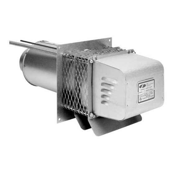
SIDEWALL POWER VENTING SYSTEM
ITEMS INCLUDED IN KIT
1 - SWGII-4HD Sidewall Power Venter
1 - CK-43F Control Kit (includes 4" MG-1 Barometric Draft Control)
1 - Installation Instructions
OPTIONAL COMPONENTS
PEK-4HD Extension Kit. For installations in walls over 8" thick.
GENERAL SYSTEM INFORMATION
Designed for operation with natural gas and LP gas.
1. The thermostat calls for heat and energizes a relay which activates the power venter. After
the venter motor has come up to speed, the pressure switch closes. This closes the circuit
to the burner and allows the burner to fire.
2. After the heating requirement has been satisfied, the thermostat circuit will open and de-
activate the burner.
3. The power venter operates for a period of time after the burner has shut off to purge
remaining flue gases.
WARNING: Bodily injury can result from high voltage electrical components, fast moving fans, and combustible
gas. For protection from these inherent hazards during installation and servicing, the electrical supply must be
disconnected and the main gas valve must be turned off. If operating checks must be performed with the unit
operating, it is the technicians responsibility to recognize these hazards and proceed safely.
Model: SWG-4G
DO NOT DESTROY
THESE INSTRUCTIONS MUST REMAIN WITH EQUIPMENT
Advertisement
Table of Contents

Subscribe to Our Youtube Channel
Related Manuals for Field Controls 46334800


Summary of Contents for Field Controls 46334800
- Page 1 SIDEWALL POWER VENTING SYSTEM Model: SWG-4G ITEMS INCLUDED IN KIT 1 - SWGII-4HD Sidewall Power Venter 1 - CK-43F Control Kit (includes 4" MG-1 Barometric Draft Control) 1 - Installation Instructions OPTIONAL COMPONENTS PEK-4HD Extension Kit. For installations in walls over 8" thick. GENERAL SYSTEM INFORMATION Designed for operation with natural gas and LP gas.
-
Page 2: Installation Safety Instructions
INSTALLATION SAFETY INSTRUCTIONS CAUTION: The power venting system must be installed by a qualified installer. "Qualified Installer" means an individual who has been properly trained or a licensed installer. The installer must write or imprint his name, phone number, and date of installation on the installation tag. - Page 3 Figure 1 Diagram A INSTALLATION FOR THE SWG POWER VENTER 1. Remove power venter from box and inspect unit for damage. If the carton has been crushed or mutilated, check unit very carefully for damage. Rotate blower wheel to insure that the motor and blower wheel rotate freely. DO NOT install if any damage is apparent.
- Page 4 Diagram B CONNECTING POWER VENTER TO APPLIANCE The venting system should be installed and supported in accordance with the National Flue Gas Code, ANSI Z223.1, CGA Standards B149.1-M91, B149.2-M91, or in accordance with any local codes. A vent pipe connector shall be supported for the design and weight of the material employed, to maintain clearances, prevent physical damage and separation of joints.
-
Page 5: Mounting Junction Box
PEK-4HD EXTENSION KIT INSTALLATION INSTRUCTIONS (Optional) (Includes an air adjustment damper plate) 1. Remove the End pan from the SWG Venter. (See Figure 5) 2. Using a pair of sheet metal cutters, cut the Damper Plate Adjustment Bracket. (See Figure 6) Then remove the Damper Plate and Adjustment Bracket. 3. - Page 6 PRESSURE SWITCH SENSING TUBE INSTALLATION 1. Attach the 1/4 inch tubing connector to the pressure tube on the SWG Venter. (See Figure 11) 2. Connect the supplied 1/4" aluminum tubing to the tubing connector. Route the tubing to the CK-43F junction box and connect the tubing to the pressure switch.
-
Page 7: Air Flow Adjustments
For further information consult Form #4199, "The Field Report - Effects of Insufficient Combustion Air" available from The Field Controls Company. PROVING SWITCH ADJUSTMENTS Refer to the following for air pressure switch adjustment procedure and system checkout procedures before operating the appliance continuously. -
Page 8: General Installation Inspection
POST PURGE TIMER The CK-43F Control Kit is designed with a non-adjustable purge timer and no adjustment is necessary. The nominal time is 1-3 minutes, and approximately 1.5 minutes is typical. ADJUSTMENTS FOR THERMOSTATS WITH HEAT ANTICIPATORS After venting kit installation and checkout, check the amperage current draw through the thermostat circuit and adjust the thermostat anticipator accordingly. -
Page 9: Maintenance
1. Motor: Inspect the motor once a year - motor should rotate freely. To prolong the life of the motor, it must be lubri- cated with six drops of SWG Superlube, Field Controls Part #46226200, annually. 2. Blower Wheel: Inspect the Power Venter blower wheel annually to clear any soot, ash, or coating which inhibits either rotation or air flow. - Page 10 Page 10...
- Page 11 INSTALLATION INFORMATION SWG-4G Sidewall Power Venting Kit MODEL NO.:____________________________________________________________ INSTALLER’S NAME:_____________________________________________________ INSTALLER’S COMPANY: _________________________________________________ INSTALLER’S PHONE NO.: ________________________________________________ DATE OF INSTALLATION:_________________________________________________ Page 11...
- Page 12 Page 12 P/N 46334800 Rev A 11/00...
Need help?
Do you have a question about the 46334800 and is the answer not in the manual?
Questions and answers