Table of Contents
Advertisement
Quick Links
SPX FLOW US, LLC
5885 11th Street
Rockford, IL 61109-3699 USA
spxflow.com/bolting-systems
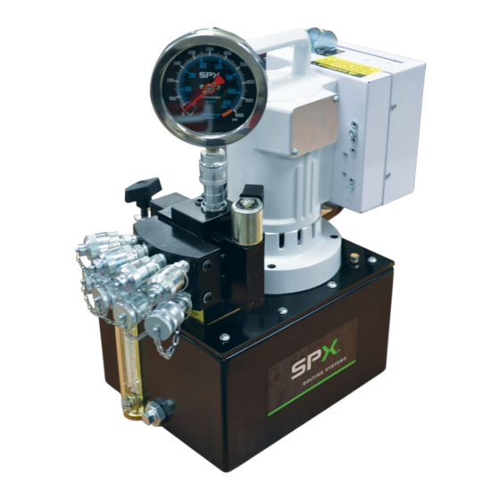
ELECTRIC HYDRAULIC PUMP
© SPX FLOW, Inc.
Tech Services: (800) 477-8326
Fax: (800) 765-8326
Order Entry: (800) 541-1418
Fax: (800) 288-7031
10,000 PSI
Operating Instructions and Parts List For:
PE55TWP-4-BS
PE55TWP-BS
PE55TWP-4-CF-BS
PE55TWP-220-BS
PE55TWP-4-220-BS
PE55TWP-4-220-CF-BS
Form No. 1000679
Rev. 7
Nov. 6, 2023
Advertisement
Table of Contents

Related Manuals for SPX FLOW Bolting Systems PE55TWP-4-BS


Summary of Contents for SPX FLOW Bolting Systems PE55TWP-4-BS
- Page 1 Operating Instructions and Parts List For: PE55TWP-4-BS PE55TWP-BS PE55TWP-4-CF-BS Tech Services: (800) 477-8326 SPX FLOW US, LLC PE55TWP-220-BS Fax: (800) 765-8326 5885 11th Street PE55TWP-4-220-BS Rockford, IL 61109-3699 USA Order Entry: (800) 541-1418 PE55TWP-4-220-CF-BS spxflow.com/bolting-systems Fax: (800) 288-7031 ELECTRIC HYDRAULIC PUMP 10,000 PSI Form No.
-
Page 2: Table Of Contents
9� Storage ������������������������������������������������������������������������������������������������������������������������������������������������ 16 10� Checking Brushes on Universal Motors ��������������������������������������������������������������������������������������������� 16 TROUBLESHOOTING GUIDE �������������������������������������������������������������������������������������������������������������������������� 17 HYDRAULIC SCHEMATIC ������������������������������������������������������������������������������������������������������������������������������� 20 PARTS LIST ������������������������������������������������������������������������������������������������������������������������������������������������������ 21 BOLTING SYSTEMS FACILITIES AND CONTACT ����������������������������������������������������������������������������������������� 53 Form No. 1000679 © SPX FLOW, Inc. Rev. 7 Nov. 6, 2023... -
Page 3: Description
Because of the many options available, these instructions will include directions for options that your particular pump may not have. • Do not change motors without consulting the pump manufacturer’s Technical Services Department. Form No. 1000679 © SPX FLOW, Inc. Rev. 7 Nov. 6, 2023... -
Page 4: Safety Symbols And Definitions
Never place your hands or other body parts near a hydraulic fluid leak. Never use your hands or other body parts to check for a possible leak. High pressure fluid can be injected under your skin causing serious injury and/or infection. Form No. 1000679 © SPX FLOW, Inc. Rev. 7 Nov. 6, 2023... - Page 5 If any of these conditions exist, replace the hose immediately. NEVER attempt to repair the hose. Form No. 1000679 © SPX FLOW, Inc. Rev. 7 Nov. 6, 2023...
- Page 6 OFF and control valve to neutral. Remove the cover on motor control box. Let the motor cool or wail until power is restored. One of three reset buttons must be pushed in to reset motor. Replace cover. Form No. 1000679 © SPX FLOW, Inc. Rev. 7 Nov. 6, 2023...
-
Page 7: Hydraulic Fluids
Note: The guide cannot cover every hazard or situation so always do the job with SAFETY FIRST. Form No. 1000679 © SPX FLOW, Inc. Rev. 7 Nov. 6, 2023... -
Page 8: Set-Up Instructions
Loose pieces of sealant could travel through the system and obstruct the flow of fluid or cause jamming of precision-fit parts. HOSES TUBING CORRECT CORRECT INCORRECT INCORRECT Fig. 1. Hoses and Tubing Connections Form No. 1000679 © SPX FLOW, Inc. Rev. 7 Nov. 6, 2023... -
Page 9: 3� Electric Motor Operation
10 (4) 8 (6) 6 (10) 12 (2�5) 10 (4) 6 (10) 4 (16) Table 1. Minimum Recommended Gauge C� Start the pump and shift as required� D� Turn off the pump when not in use. Form No. 1000679 © SPX FLOW, Inc. Rev. 7 Nov. 6, 2023... -
Page 10: 4� Adjusting The Hydraulic Gauge
After all connections are made, the hydraulic system must be bled of any trapped air� With no load on the system and the pump vented and positioned higher than the hydraulic device, cycle the system several times. Check the reservoir fluid level and fill to proper level with Power Team hydraulic fluid as necessary. If there is a problem contact the Power Team� Form No. 1000679 © SPX FLOW, Inc. Rev. 7 Nov. 6, 2023... -
Page 11: Control Valves
Controlled, Pilot Advance Retract Operated, 1 Tool) Diagram Port “A” Port “B” Port “B” PE55TWP-220-BS Port “A” PE55TWP-BS From From Pump Pump Tank Tank Table 2. Pump Configurations Form No. 1000679 © SPX FLOW, Inc. Rev. 7 Nov. 6, 2023... -
Page 12: Performance Specification
(100 psi) (700 psi) (1,000 psi) (5,000 psi) (10,000 psi) (psi) 690 bar PE55TWP-4-BS (10,000 psi) Typical delivery. Actual flow varies with field conditions. Table 4. Fluid Pressure Chart Form No. 1000679 © SPX FLOW, Inc. Rev. 7 Nov. 6, 2023... -
Page 13: Operation
NOTE: If pump is turned off by operator or if the built in retract timer shuts down the unit, follow C, D and E sequence above to ensure restart. Fig. 4. Hand Pendant Controller Form No. 1000679 © SPX FLOW, Inc. Rev. 7 Nov. 6, 2023... -
Page 14: 3� Pressure Regulating Controls
IMPORTANT: The pressure range is from 1,000 to 10,000 PSI (69 to 690 BAR) depending on the pump model. Adjusting screw or Knob Lock Nut Fig. 5. Pressure Regulator Valve Form No. 1000679 © SPX FLOW, Inc. Rev. 7 Nov. 6, 2023... -
Page 15: Preventive Maintenance
B� Drain, flush, and refill the reservoir with an approved, high-grade hydraulic oil after every 300 hours of use� The frequency of oil changes depends upon general working conditions, severity of use, the overall cleanliness and care given to the pump� Form No. 1000679 © SPX FLOW, Inc. Rev. 7 Nov. 6, 2023... -
Page 16: 5� Draining And Flushing The Reservoir
A� Install a pressure switch to automatically shut off the motor when maximum pressure is reached (holding cycle)� B� Install casters (7�5L (2 Gallon) reservoir only)� C� Contact Power Team Hydraulic Technology technical support for products more suitable to your application� Form No. 1000679 © SPX FLOW, Inc. Rev. 7 Nov. 6, 2023... -
Page 17: 8� Hose Connections
C� The brush assemblies must be replaced if they are 4�5mm (1/8") long or less� See Figure 7� D� Install brush assemblies, brush holder caps, and metal brush cover plates� Replace when 4.5 mm (1/8") or less 22 mm (7/8") (new) Fig. 7. Brush Inspection Form No. 1000679 © SPX FLOW, Inc. Rev. 7 Nov. 6, 2023... -
Page 18: Troubleshooting Guide
2� Refer to electrical cord chart in Initial Setup section� Electrical overload protector 1� Wired incorrectly� 1� Disconnect unit from power keeps tripping. supply; have qualified electrician review motor and circuit wiring� Form No. 1000679 © SPX FLOW, Inc. Rev. 7 Nov. 6, 2023... - Page 19 If using a double-acting tool, remove it from the system to ensure the leak is not in the tool� Seal leaking pipe fittings with pipe sealant� 2� Leaking pressure switch seal� 2� Replace pressure switch� Form No. 1000679 © SPX FLOW, Inc. Rev. 7 Nov. 6, 2023...
- Page 20 3� Attached component sticking or 3� Refer to manufacture's binding� information for attached component� 4� Malfunctioning valve� 4� Verify connections� Contact authorized Power Team Service Center� Form No. 1000679 © SPX FLOW, Inc. Rev. 7 Nov. 6, 2023...
-
Page 21: Hydraulic Schematic
RETRACT PORT PRESSURE CONTROL 110 BAR (1,600 PSI) RETRACT ADVANCE EXTERNAL PRESSURE REGULATOR 703 BAR (10,200 PSI) LOW PRESSURE UNLOADING VALVE 69 BAR (1,000 PSI) SUPERCHARGE PRESSURE REGULATOR 14 BAR (200 PSI) Form No. 1000679 © SPX FLOW, Inc. Rev. 7 Nov. 6, 2023... -
Page 22: Parts List
PARTS LIST Basic Pump Assembly Side View Form No. 1000679 © SPX FLOW, Inc. Rev. 7 Nov. 6, 2023... - Page 23 MOTOR CONTROL ASSEMBLY(115 VAC) 3000116 MOTOR CONTROL ASSEMBLY(230 VAC) PARTS INCLUDED BUT NOT SHOWN 21091 DRIVE COUPLING Part numbers marked with an asterisk (*) are contained in valve assembly (No. 3000113) Form No. 1000679 © SPX FLOW, Inc. Rev. 7 Nov. 6, 2023...
- Page 24 (5 in-lbs) 3000113BK DIRECTIONAL VALVE 351095 VALVE GASKET 251906 PRODUCT NAME PLATE 10575 DRIVE SCREW 40164 RESERVOIR RECT GASKET 350925 FILLER CAP 250447 DECAL, WARNING NO USE HAZ ENVIROMENT Form No. 1000679 © SPX FLOW, Inc. Rev. 7 Nov. 6, 2023...
- Page 25 SCREW, SHC 1/4-20 X 1�00 HEX HD 21344 FILTER SCREEN 15456 STRAIGHT FITTING 41064-2 PUMP BASIC - USE 27207 FOR REP PARTS 252056 PRESSURE REGULATOR TUBE 16177 TUBE FITTING 420963 PRESSURE REGULATOR Form No. 1000679 © SPX FLOW, Inc. Rev. 7 Nov. 6, 2023...
- Page 26 Parts List Continued Cover Plate Assembly Bottom View #3000646 "A" "A" SECTION "A-A" Form No. 1000679 © SPX FLOW, Inc. Rev. 7 Nov. 6, 2023...
- Page 27 10431 FITTING, NUT 5/8-18 F (3/8 OD Tube) 10266 O-RING 10015 SCREW, 1/4-28 X 1�00 (Torque to 15-20 Nm (130-180 in-lbs�)) 21277-2 CHECK AND 10000 PSI RELIEF VALVE Form No. 1000679 © SPX FLOW, Inc. Rev. 7 Nov. 6, 2023...
- Page 28 SPRING SLEEVE 215431 (Note: Assemble closed coils of spring form towards fitting seat (Item #7)) 215683 REGULATOR LOCK NUT 215693 KNOB *215430 WASHER 10266 O-RING Part numbers marked with an asterisk (*) are contained in repair kit (No. 9633-KIT). Form No. 1000679 © SPX FLOW, Inc. Rev. 7 Nov. 6, 2023...
- Page 29 Parts List Continued Basic Pump #41064-2 .105/.095 NEEDLE When replacing the needle bearings on the driver gear BEARINGS of the basic pump, the dimensions shown must be as specified .105/.095 Form No. 1000679 © SPX FLOW, Inc. Rev. 7 Nov. 6, 2023...
- Page 30 21092 ADAPTER 21093 "C" KEY 10303 O-RING 10425 SPRING COMPRESSION 20771 POPPET 10271 O-RING 12389 BACKUP WASHER 20849 SPOOL 23255 SPRING GUIDE 10426 SPRING COMPRESSION 23256 SPRING GUIDE Form No. 1000679 © SPX FLOW, Inc. Rev. 7 Nov. 6, 2023...
- Page 31 Parts List Continued High Pressure Pump Assembly #33113 2X SCALE 2X SCALE Form No. 1000679 © SPX FLOW, Inc. Rev. 7 Nov. 6, 2023...
-
Page 32: High Pressure Pump Assembly
*Consult factory when replacing items marked with an asterisk (*) High Pressure Pump Assembly Bolt Tightening Sequence Assemble in sequence shown� Lubricate under heads and on threads� Torque to 20�5 Nm (180 in� lbs)� Form No. 1000679 © SPX FLOW, Inc. Rev. 7 Nov. 6, 2023... - Page 33 Parts List Continued Exploded View of Motor #53337 / #53338 “A” “A” Form No. 1000679 © SPX FLOW, Inc. Rev. 7 Nov. 6, 2023...
- Page 34 Place motor in upright position while Loctite® #277 or equivalent cures� 10241 LOCK WASHER Torque to 2�5 Nm 10169 PAN SCREW (22 in-lbs�) 40059WH2 MOTOR BASE Form No. 1000679 © SPX FLOW, Inc. Rev. 7 Nov. 6, 2023...
-
Page 35: Brush Holder
Brush Holder and Armature Installation Specifications When replacing brushes or the armature, the dimensions shown must be specified. VIEW “A-A” ITEM DESCRIPTION 17-18 MM (�677 - �702) BOTH SIDES �51 MM (�020) MINIMUM TYPICAL �51 MM (�020) MINIMUM TYPICAL ARMATURE BRUSHES Form No. 1000679 © SPX FLOW, Inc. Rev. 7 Nov. 6, 2023... - Page 36 Parts List Continued Motor Control Assembly #3000114 / #3000116 GRD−1 VIEW A−A 9 10 "A" "A" GRD−1 GROUND Form No. 1000679 © SPX FLOW, Inc. Rev. 7 Nov. 6, 2023...
- Page 37 ROUND SCREW 10196 HEX NUT 51218WH2 ELECTRICAL CONTROL BOX 421477 CIRCUIT BOARD HEX NUT ANTI-ROTATION KEY WASHER INTERNAL TOOTH LOCK WASHER 352061 SWITCH GUARD HEX NUT CONTROL BOX Form No. 1000679 © SPX FLOW, Inc. Rev. 7 Nov. 6, 2023...
- Page 38 TB-4 BLACK TB-3 HANDSWITCH TO GROUND GREEN TB-6 WHITE TB-5 TB-1 SOLENOID LEADS TB-2 VALVE DETAIL TORQUE SPOOL TORQUE NUT TO 168-192 IN. LBS. TO 48-72 IN. LBS. Form No. 1000679 © SPX FLOW, Inc. Rev. 7 Nov. 6, 2023...
- Page 39 0�66 Part numbers marked with an asterisk (*) are replaced with service kit 3001259 or 3001260. 3001259 if the valve is 120VAC. 3001260 if the valve is 240VAC. Form No. 1000679 © SPX FLOW, Inc. Rev. 7 Nov. 6, 2023...
- Page 40 Parts List Continued Remote Hand Switch #351160 Form No. 1000679 © SPX FLOW, Inc. Rev. 7 Nov. 6, 2023...
- Page 41 13402 BLACK WIRE 0�62 Black Circuit #2 green Circuit #1 white Both ends of the green RED HEAT SHRINK wire PARTS INCLUDED BUT NOT SHOWN 4453-AA NYLON BUSHING Form No. 1000679 © SPX FLOW, Inc. Rev. 7 Nov. 6, 2023...
- Page 42 Parts List Continued Valve Assembly #3000113BK SECTION A-A Form No. 1000679 © SPX FLOW, Inc. Rev. 7 Nov. 6, 2023...
- Page 43 SCREW, SHC 10-24 X 1�25 (Torque to 6-8 Nm (50-70 in-lbs�)) 14844 STRAIGHT FITTING 10661 STRAIGHT TUBE FITTING 10479 PLUG FITTING 1400-AA PLASTIC PACKAGING PLUG 65095BK VALVE BODY Form No. 1000679 © SPX FLOW, Inc. Rev. 7 Nov. 6, 2023...
- Page 44 Part numbers marked with an asterisk (*) are contained in valve assembly (No. 3000113) Part numbers marked with a double asterisk (**) are contained in repair kit (No. 3000590) Form No. 1000679 © SPX FLOW, Inc. Rev. 7 Nov. 6, 2023...
- Page 45 Parts List Continued Valve Assembly #421293BK SECTION A-A 29 30 31 32 Form No. 1000679 © SPX FLOW, Inc. Rev. 7 Nov. 6, 2023...
- Page 46 SCREW, SHC 1/4-20 X 1�75 (Torque to 17-20 Nm (150-180 in-lbs�)) 420902BK LEFT END CAP 11151 SCREW, SHC 10-24 X 1�25 10479 PLUG FITTING 1400-AA PLASTIC PACKAGING PLUG 65095BK VALVE BODY Form No. 1000679 © SPX FLOW, Inc. Rev. 7 Nov. 6, 2023...
- Page 47 Part numbers marked with an asterisk (*) are contained in valve assembly (No. 3000113) Part numbers marked with a double asterisk (**) are contained in repair kit (No. 3000590) Form No. 1000679 © SPX FLOW, Inc. Rev. 7 Nov. 6, 2023...
- Page 48 Parts List Continued Oil Cooled Hydraulic Pump 10,000 PSI Form No. 1000679 © SPX FLOW, Inc. Rev. 7 Nov. 6, 2023...
- Page 49 Parts List Continued Oil Cooled Hydraulic Pump 10,000 PSI Continued Form No. 1000679 © SPX FLOW, Inc. Rev. 7 Nov. 6, 2023...
- Page 50 BRACKET, OIL COOLER MTG 2000578 FAN, COOLER 230V, ASSEMBLY 3000113BK VALVE DIRECTIONAL - 3P3W MOTOR AND CONTROL ASSEMBLY - 200V, 50/60 Hz, W/VALVE 3000116 ASSEMBLY 3000136BK2 COVERPLATE ASSEMBLY Form No. 1000679 © SPX FLOW, Inc. Rev. 7 Nov. 6, 2023...
- Page 51 Parts List Continued Coverplate Assembly #3000136 Form No. 1000679 © SPX FLOW, Inc. Rev. 7 Nov. 6, 2023...
- Page 52 Parts List Continued Coverplate Assembly #3000136 (Continued) SECTION A-A (2000245 - USED ON 3000136) (2000245WH2 - USED ON 3000136WH2) (2000245BK2 - USED ON 3000136BK2) Form No. 1000679 © SPX FLOW, Inc. Rev. 7 Nov. 6, 2023...
- Page 53 420963 REGULATOR ASSEMBLY - EXTERNAL PRESSURE 2000242 SCREW, SOCKET HEAD CAP #10-32 x 2-1/2 2000243 TUBE, OIL LINE 2000244 BLOCK, ADAPTER (Note: Unloading for cooler) 2000245 PLATE, COVER Form No. 1000679 © SPX FLOW, Inc. Rev. 7 Nov. 6, 2023...
-
Page 54: Bolting Systems Facilities And Contact
Corpus Christi, Texas USA India India Australia Australia 318 Centaurus Street 318 Centaurus Street SPX Flow Technology (India) Pvt� SPX Flow Technology (India) Pvt� SPX Flow Technology Austra- SPX Flow Technology Austra- Corpus Christi, Texas 78405 USA Corpus Christi, Texas 78405 USA Limited...
Need help?
Do you have a question about the Bolting Systems PE55TWP-4-BS and is the answer not in the manual?
Questions and answers