SPX FLOW PB102 Parts List And Operating Instructions
Battery powered hydraulic pump
Hide thumbs
Also See for PB102:
- Parts list and operating instructions (44 pages) ,
- Parts list and operating instructions (46 pages)
Table of Contents
Advertisement
Quick Links
SPX FLOW US, LLC
5885 11th Street
Rockford, IL 61109-3699 USA
powerteam.com
© SPX FLOW, Inc.
Tech Services: (800) 477-8326
Fax: (800) 765-8326
Order Entry: (800) 541-1418
Fax: (800) 288-7031
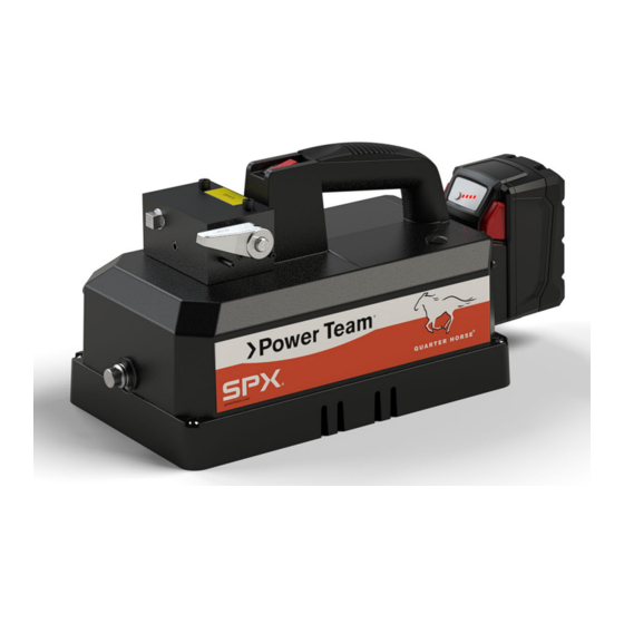
MODEL B
BATTERY POWERED
HYDRAULIC PUMP
Parts List and Operating Instructions for:
PB102
PB102-0
PB102-1
PB102-2
PB102-3
PB102-X
PB102A
PB102A-0
PB102A-1
PB102A-2
Note: PB10X units ending in "-1" are not CE/UKCA certified.
1
PB102A-3
PB102R-1
PB104-X
PB102A-X
PB102R-2
PB102-CP-1
PB102P
PB102R-3
PB102-CP-2
PB102P-0
PB102R-X
PB102-CP-3
PB102P-1
PB102-CP
PB102P-2
PB104
PB102P-3
PB104-0
PB102P-X
PB104-1
PB102R
PB104-2
PB102R-0
PB104-3
Form No. 1001044
Rev. 4
Dec. 7, 2021
Advertisement
Table of Contents

Related Manuals for SPX FLOW PB102


Summary of Contents for SPX FLOW PB102
- Page 1 PB102-0 PB102A-X PB102R-2 PB102-CP-1 PB102-1 PB102P PB102R-3 PB102-CP-2 PB102-2 PB102P-0 PB102R-X PB102-CP-3 SPX FLOW US, LLC Tech Services: (800) 477-8326 PB102-3 PB102P-1 PB102-CP 5885 11th Street Fax: (800) 765-8326 PB102-X PB102P-2 PB104 Rockford, IL 61109-3699 USA Order Entry: (800) 541-1418...
-
Page 2: Table Of Contents
PB10 Series Hydrulic Pump 65187-18 (Pump Sub-assembly, Electric 18VDC) 350622 (Valve, Manual, 2-Position 2-Way) 420558 (Valve, Manual, 3-Position 4-Way) 350623 (Body, Valve Pressure Regulator) 350720 (Manifold Assembly) 3001123 (Manifold Assembly) © SPX FLOW, Inc. Form No. 1001044 Rev. 4 Dec. 7, 2021... - Page 3 Table of contents continued ELECTRICAL SCHEMATIC HYDRAULIC SCHEMATIC POWER TEAM FACILITIES & CONTACT MILWAUKEE ELECTRIC TOOL CORPORATION CONTACT EC DECLARATION OF CONFORMITY UKCA DECLARATION OF CONFORMITY © SPX FLOW, Inc. Form No. 1001044 Rev. 4 Dec. 7, 2021...
-
Page 4: Safety Symbols And Definitions
Disconnect the battery from the pump and relieve pressure before opening any connections in the system. • The guide cannot cover every hazard or situation so always do the job with SAFETY FIRST. © SPX FLOW, Inc. Form No. 1001044 Rev. 4 Dec. 7, 2021... -
Page 5: General
Avoid slipping or falling by cleaning up any oil spills. • Avoid back injury by always lifting equipment carefully. • It is strongly recommended to view the Power Team Hydraulic Safety video tape before using hydraulic equipment. © SPX FLOW, Inc. Form No. 1001044 Rev. 4 Dec. 7, 2021... -
Page 6: Power Supply
Hose deterioration due to corrosive materials can result in personal injury. Consult the manufacturer before painting a hose. Never paint a coupler. © SPX FLOW, Inc. Form No. 1001044 Rev. 4... -
Page 7: Pump
Hydraulic fluids • Properly dispose of all fluids, components, and assemblies at the end of their useful life. • Hydraulic fluid should be compatible with all hydraulic components. © SPX FLOW, Inc. Form No. 1001044 Rev. 4 Dec. 7, 2021... -
Page 8: Description
*** Models designated with (-X) do not include battery or charger; pump only. Pictured: PB102R Valve control lever Battery Pack Start button Oil Bladder Fill Port Pressure regulator adjustment knob © SPX FLOW, Inc. Form No. 1001044 Rev. 4 Dec. 7, 2021... - Page 9 Charging will begin when first pack is fully charged. * Items only on multi voltage charger models Flashing red/green: Damaged or faulty battery pack ** When charging M12 & M18 packs simultaneously © SPX FLOW, Inc. Form No. 1001044 Rev. 4 Dec. 7, 2021...
-
Page 10: Setup Instructions
D. Replace filler cap. IMPORTANT: Tighten filler cap ONLY 1/2 - 1 turn (MAX) after O-ring contacts sealing surfaces. Overtightening can cause pump damage on bladder equipped pumps. B. to C. © SPX FLOW, Inc. Form No. 1001044 Rev. 4 Dec. 7, 2021... -
Page 11: Hydraulic Lines And Fittings
C. Once battery is adequately charged it can be installed on pump unit as shown. D. To remove the battery from the pump unit press the release buttons on the sides of the battery. E. Slide the battery out of the pump unit as shown. © SPX FLOW, Inc. Form No. 1001044 Rev. 4... - Page 12 Setup Instructions continued © SPX FLOW, Inc. Form No. 1001044 Rev. 4 Dec. 7, 2021...
-
Page 13: Bleeding The System
This type of cylinder or ram should be bled when positioned upside down or lying on its side with the port facing upward. System with a double-acting cylinder System with a single acting cylinder © SPX FLOW, Inc. Form No. 1001044 Rev. 4 Dec. 7, 2021... -
Page 14: Pump Operation
C. Secure the connection by threading (rotating clockwise) the cable fitting into the pump unit fitting. D. To activate the pump unit press and hold the start button, release the start button and the pump unit will stop running. Alignment © SPX FLOW, Inc. Form No. 1001044 Rev. 4 Dec. 7, 2021... - Page 15 Pump Operation continued Alignment Groove Start Button © SPX FLOW, Inc. Form No. 1001044 Rev. 4 Dec. 7, 2021...
-
Page 16: Lifting Or Lowering A Load With A Hydraulic Cylinder
B. The use of blocking and cribbing is recommended to help prevent a falling load. C. The use of a load lowering or metering valve is recommended in addition to the correct directional control valve to help prevent a falling load. © SPX FLOW, Inc. Form No. 1001044 Rev. 4... -
Page 17: Directional Control Valve Options
To prevent sudden, uncontrolled descent of a load as it is being lowered, use Load Lowering Valve (No. 9596) or Counter Balance Valve (No. 9720) in conjunction with the 4-way manual valve in your application © SPX FLOW, Inc. Form No. 1001044 Rev. 4... -
Page 18: Position, 2-Way Manual Valve
HOLD pressure. D. To retract the cylinder, turn the valve control handle clockwise (CW) slowly, (See Figure 3) Valve control lever Port Figure 2 Figure 3 © SPX FLOW, Inc. Form No. 1001044 Rev. 4 Dec. 7, 2021... -
Page 19: Position, 4-Way Manual Valve
NOTE: Non “posi-check” valves will momentarily lose pressure when shifting to HOLD position. E. Retract the cylinder by shifting the valve control lever to the RETRACT (Port B) position. F. Activate the pump unit if using double-acting cylinders. © SPX FLOW, Inc. Form No. 1001044 Rev. 4... - Page 20 DOUBLE-ACTING CYLINDER(S) IN THE CIRCUIT CONTROLLED BY A PUMP-MOUNTED VALVE CONTROLLED BY A PUMP-MOUNTED VALVE Other valves are available. Consult your dealer, catalog or valve operating instructions for details of operation. © SPX FLOW, Inc. Form No. 1001044 Rev. 4 Dec. 7, 2021...
-
Page 21: Adjusting The Pressure Regulating Controls
(B). Shut off the pump. IMPORTANT: The pressure range is from 1,000 to 10,000 PSI (70 to 700 BAR) depending on the pump model. Figure 6 © SPX FLOW, Inc. Form No. 1001044 Rev. 4 Dec. 7, 2021... -
Page 22: Preventive Maintenance
IMPORTANT: Tighten filler cap ONLY 1/2 - 1 turn (MAX) after O-ring contacts sealing surfaces. Overtightening can cause pump damage on bladder equipped pumps. NOTE: For more complete instructions, reference “Checking Hydraulic Fluid and Filling the Bladder” under SETUP INSTRUCTIONS. © SPX FLOW, Inc. Form No. 1001044 Rev. 4 Dec. 7, 2021... -
Page 23: Maintenance Cleaning
WARNING suspect area. Watch for leaking fluid and follow it back to its source. Never use your hand or other body parts to check for a possible leak. © SPX FLOW, Inc. Form No. 1001044 Rev. 4 Dec. 7, 2021... - Page 24 4. Hydraulic fluid is of a higher viscous. viscosity than necessary. Change to a lighter fluid. 5. Bladder capacity is too 5. Use smaller cylinder(s). small for the size of cylinder(s) used. © SPX FLOW, Inc. Form No. 1001044 Rev. 4 Dec. 7, 2021...
- Page 25 Authorized Hydraulic Service Center. 5. Inadequate power supply. 5. Refer to “Pump Operation” section. 6. Leaking control valve or 6. Contact a Power Team defective pump. Authorized Hydraulic Service Center. © SPX FLOW, Inc. Form No. 1001044 Rev. 4 Dec. 7, 2021...
- Page 26 1. Faulty pressure gauge. 1. Calibrate gauge. Pump delivers excess oil 2. Relief valve not properly 2. Contact a Power Team pressure. set. Authorized Hydraulic Service Center. © SPX FLOW, Inc. Form No. 1001044 Rev. 4 Dec. 7, 2021...
-
Page 27: Parts List
PARTS LIST PB10 Series Hydraulic Pump © SPX FLOW, Inc. Form No. 1001044 Rev. 4 Dec. 7, 2021... -
Page 28: 420558 (Valve, Manual, 3-Position 4-Way)
PLUG, O RING BOSS: 1/2-20 UNF 252871 NUT, HEX ACORN CAP #10-32 (TORQUE TO 30/40 IN. LBS.) 350583 ADAPTER, FILLER VALVE, MANUAL, 2 POSITION, 2 -WAY (Used on PB102, PB102P, 350622 PB102R) 420558 VALVE, MANUAL (3-POSITION, 4-WAY) (Used on PB104) - Page 29 DECAL, PLAS CERT CE US RECT 4.25IN (Used on PB102R) 1001031 DECAL, PLAS CERT CE US RECT 4.25IN (Used on PB102A) 1001054 DECAL, PLAS CERT CE US RECT 4.25IN (Used on PB102) 1001055 DECAL, PLAS CERT CE US RECT 4.25IN (Used on PB104) 1001143 DECAL, PLAS CERT CE US RECT 4.25IN (Used on PB102-CP)
- Page 30 REMOTE PUMP HAND SWITCH ASSEMBLY (included with PB102P) 2009646 CHARGER, LI-ION BATTERY 120VAC (Used with PB10XX-1 Models) 2009647 CHARGER, LI-ION BATTERY 240VAC (Used with PB10XX-2 Models) 2010141 CHARGER, LI-ION BATTERY 240VAC (Used with PB10XX-3 Models) © SPX FLOW, Inc. Form No. 1001044 Rev. 4 Dec. 7, 2021...
-
Page 31: 65187-18 (Pump Sub-Assembly, Electric 18Vdc)
Parts List continued 65187-18 (Pump Sub-assembly, electric 18VDC) SECTION A-A DETAIL F SECTION B-B SECTION C-C © SPX FLOW, Inc. Form No. 1001044 Rev. 4 Dec. 7, 2021... - Page 32 Parts List continued SECTION D-D MOTOR END VIEW © SPX FLOW, Inc. Form No. 1001044 Rev. 4 Dec. 7, 2021...
- Page 33 SCREW, SHC 10-24 X 1.250 (TORQUE TO 60/80 IN. LBS.) 251040 PIN, DOWEL .13 X .25 251061 PIN, DOWEL .06 X .38 251062 PISTON 5/32 DIA. 251063 O-RING, -027 1.301x0.07x1.441IN, NBR 70 251064 SEAT, REPLACEABLE © SPX FLOW, Inc. Form No. 1001044 Rev. 4 Dec. 7, 2021...
- Page 34 PLATE, PUMP END (FOR PUMP SUBASSY BUILT BEFORE DEC. 2021) 64347 PLATE, END 2009972 PIN, ROLL 0.156x0.555IN ST BOX 15695 BEARING, SPH ROL 1.375IN × 0.625 × 0.281 © SPX FLOW, Inc. Form No. 1001044 Rev. 4 Dec. 7, 2021...
-
Page 35: 350622 (Valve, Manual, 2-Position 2-Way)
FITTING, PLUG - 3/8 NPTF M FLUSH 251279 FITTING, PLUG 1/8 PTF 10556 SCREW, SET 1/4-20 X 0.25 KNURLED CUP (TORQUE TO 30/50 IN. LBS.) 251512 DECAL, TELEPHONE INFORMATION 251472 DECAL, WARNING VALVE © SPX FLOW, Inc. Form No. 1001044 Rev. 4 Dec. 7, 2021... - Page 36 Parts List continued 420558 (Valve, Manual 3-Position, 4-Way) 22 6X 10 2X © SPX FLOW, Inc. Form No. 1001044 Rev. 4 Dec. 7, 2021...
- Page 37 24570 SHEAR SEAL 251128 BUSHING, OUTLET CHECK 251279 FITTING, PLUG 1/8 PTF 251512 DECAL, TELEPHONE INFORMATION 25821BK2 COVER, VALVE - MACHINED 32070 STEM 32071 ROTOR 64374 BODY, VALVE © SPX FLOW, Inc. Form No. 1001044 Rev. 4 Dec. 7, 2021...
-
Page 38: 350623 (Body, Valve Pressure Regulator)
Parts List continued 350623 (Body, Valve pressure Regulator) © SPX FLOW, Inc. Form No. 1001044 Rev. 4 Dec. 7, 2021... - Page 39 CAP, VALVE 21306 GUIDE, SPRING 215683 NUT, 3/8-24 REGULATOR LOCK 350625 GUIDE, BALL 58350 BODY, VALVE PRESSURE REGULATOR T1-1019-01 PLUG, 1/8-27 NPT FLUSH PLUMBING (TORQUE TO 120 IN. LBS.) © SPX FLOW, Inc. Form No. 1001044 Rev. 4 Dec. 7, 2021...
-
Page 40: 350720 (Manifold Assembly)
FITTING, PLUG - 3/8 NPTF M FLUSH 11127 FITTING, PLUG 3/8 NPTF W/SEALANT 14972 FITTING, PLUG - 1/4 PTF FLUSH 251279 FITTING, PLUG 1/8 PTF 251512 DECAL, TELEPHONE INFORMATION 58349 BODY, MANIFOLD © SPX FLOW, Inc. Form No. 1001044 Rev. 4 Dec. 7, 2021... -
Page 41: 3001123 (Manifold Assembly)
FITTING, PLUG 1-5/16-12 ORB 251512 DECAL, TELEPHONE INFORMATION 2010235 BODY, MANIFOLD 2010291 BODY, VALVE (TORQUE TO 40/50 FT. LBS.) PLUG, 1/8-27 NPT FLUSH PLUMBING T1-1019-01 (TORQUE TO 180/200 IN. LBS.) © SPX FLOW, Inc. Form No. 1001044 Rev. 4 Dec. 7, 2021... -
Page 42: Electrical Schematic
BLUE (+) L2 (-) CAPACITOR CAPACITOR DIODE DIODE 30 AMP FUSE INPUT OUTPUT INPUT OUTPUT 30 AMP FUSE AUTO RESET AUTO RESET CONNECTOR CONNECTOR OPTIONAL OPTIONAL REMOTE REMOTE © SPX FLOW, Inc. Form No. 1001044 Rev. 4 Dec. 7, 2021... -
Page 43: Hydraulic Schematic
150 PSI. 150 PSI. 9,800 PSI. 9,800 PSI. AUTO. AUTO. VALVE VALVE TO VALVE TO VALVE LOW PRESSURE LOW PRESSURE UNLOADING VALVE UNLOADING VALVE 425 PSI. 425 PSI. © SPX FLOW, Inc. Form No. 1001044 Rev. 4 Dec. 7, 2021... -
Page 44: Power Team Facilities & Contact
POWER TEAM FACILITIES & CONTACT MILWAUKEE TOOL CORPORATION CONTACT www.milwaukeetool.com Milwaukee Tool Customer Service: (800) 729-3878 © SPX FLOW, Inc. Form No. 1001044 Rev. 4 Dec. 7, 2021... -
Page 45: Ec Declaration Of Conformity
English Original EC DECLARATION OF CONFORMITY We declare under our sole responsibility that our Electric Pump Model: PB102, PB102P, PB102R, PB102A, PB102-CP, PB102-0, PB102P-0, PB102R-0, PB102A-0, PB102-2, PB102P-2, PB102R-2, PB102A-2, PB102-CP-2, PB102-3, PB102P-3, PB102R-3, PB102A-3, PB102-CP-3, PB104, PB104-0, PB104-2, PB104-3, PB102-X,... -
Page 46: Ukca Declaration Of Conformity
UKCA DECLARATION OF CONFORMITY We declare under our sole responsibility that our Electric Pump Model: PB102, PB102P, PB102R, PB102A, PB102-CP, PB102-0, PB102P-0, PB102R-0, PB102A-0, PB102-2, PB102P-2, PB102R-2, PB102A-2, PB102-CP-2, PB102-3, PB102P-3, PB102R-3, PB102A-3, PB102-CP-3, PB104, PB104-0, PB104-2, PB104-3, PB102-X, PB102A-X, PB102P-X, PB102R-X, PB104-X to which this declaration relates are in conformity with the following: Legislation &...
Need help?
Do you have a question about the PB102 and is the answer not in the manual?
Questions and answers