Table of Contents
Advertisement
Quick Links
SPX FLOW US, LLC
5885 11th Street
Rockford, IL 61109-3699 USA
spxflow.com/bolting-systems
LCD USER INSTRUCTIONS
© SPX FLOW, Inc.
Tech Services: (800) 477-8326
Fax: (800) 765-8326
Order Entry: (800) 541-1418
Fax: (800) 288-7031
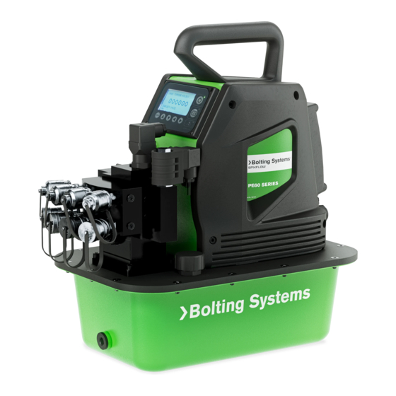
PE60 Series Electric Hydraulic Pumps with
LCD Display
Model shown for PE604BH1P
Operating Instruction For:
PE60 SERIES
Form No. 1001338
Rev. 0
Sep. 6, 2023
Advertisement
Table of Contents

Related Manuals for SPX FLOW Bolting Systems PE60 Series


Summary of Contents for SPX FLOW Bolting Systems PE60 Series
- Page 1 Operating Instruction For: PE60 SERIES Tech Services: (800) 477-8326 SPX FLOW US, LLC Fax: (800) 765-8326 5885 11th Street Rockford, IL 61109-3699 USA Order Entry: (800) 541-1418 spxflow.com/bolting-systems Fax: (800) 288-7031 LCD USER INSTRUCTIONS PE60 Series Electric Hydraulic Pumps with...
-
Page 2: Table Of Contents
1� LCD Operational Buttons����������������������������������������������������������������������������������������������������������������������3 2� LCD Startup Splash Screen�����������������������������������������������������������������������������������������������������������������4 3� Menu Mode Options�����������������������������������������������������������������������������������������������������������������������������6 4� Menu Mode Summary���������������������������������������������������������������������������������������������������������������������������7 FAULT MODE GUIDE �������������������������������������������������������������������������������������������������������������������������������������� 13 BOLTING SYSTEMS FACILITIES AND CONTACT ������������������������������������������������������������������������������������������ 14 © SPX FLOW, Inc. Form No. 1001338 Rev. 0 Sep. 6, 2023... -
Page 3: Description
Service Oil Motor ON Maintenance (PM) or Filter Output Screen Screen Navigation MENU MODE Menu Screen OPERATION CLEAR DISPLAY LCD BACKLIGHT Cursor LCD HEATER ENTER spxflow.com Menu Screen © SPX FLOW, Inc. Form No. 1001338 Rev. 0 Sep. 6, 2023... -
Page 4: Lcd Functions
LEFT ARROW - Used to move the cursor left direction� RIGHT ARROW - Used to move the cursor right direction� FAULT LIGHT - Illuminates when a fault error is detected� © SPX FLOW, Inc. Form No. 1001338 Rev. 0 Sep. 6, 2023... -
Page 5: 2� Lcd Startup Splash Screen
– pump will still operate, Screen 4 but on all other running screens, wrench will stay displayed until it’s cleared in maintenance mode� © SPX FLOW, Inc. Form No. 1001338 Rev. 0 Sep. 6, 2023... - Page 6 “A” or “B”� ENTER spxflow.com Screen 6 J� Refer to Screen 7� Shows pressure mode “OUTPUT SCREEN” when motor in OFF state� ENTER spxflow.com Screen 7 © SPX FLOW, Inc. Form No. 1001338 Rev. 0 Sep. 6, 2023...
-
Page 7: 3� Menu Mode Options
User can enter into “MENU MODE” with the motor only in off state. • In the “MENU MODE” when a setting is set as default, it will be inverted (black background / white text). • Cursor will show position. © SPX FLOW, Inc. Form No. 1001338 Rev. 0 Sep. 6, 2023... -
Page 8: 4� Menu Mode Summary
D. LCD HEATER • PRESS ENTER TO SET DEFAULT VALUES 1� LOW (Default setting) (NOTE: THIS DOES NOT CLEAR HISTORY OR FAULTS DATA) 2� MEDIUM 3� HIGH EXIT 4� EXIT © SPX FLOW, Inc. Form No. 1001338 Rev. 0 Sep. 6, 2023... - Page 9 Use the “▲▼“ buttons to select desired unit, then press the “ENTER” button (Refer to screens 13 and 14)� PRESSURE TORQUE Lb. ft. 2. BAR 2. Nm 3. MPa ENTER ENTER spxflow.com spxflow.com Screen 13 Screen 14 © SPX FLOW, Inc. Form No. 1001338 Rev. 0 Sep. 6, 2023...
- Page 10 (Refer to screens 17 and 18) (MAX. TORQUE = 0) TORQUE TARGET 00000 00000 TARGET: 0 lb. ft. lb. ft. ENTER ENTER spxflow.com spxflow.com Screen 17 Screen 18 © SPX FLOW, Inc. Form No. 1001338 Rev. 0 Sep. 6, 2023...
- Page 11 3� HIGH MEDIUM HIGH 4� EXIT EXIT • Use the “▲▼” buttons to select desired temperature, then press the “ENTER” ENTER button (Refer to screen 21)� spxflow.com Screen 21 © SPX FLOW, Inc. Form No. 1001338 Rev. 0 Sep. 6, 2023...
- Page 12 6 dots will light up in sequential (from left to right) during system test and “OK” will Screen 24 appear once system check has finished successfully� • Once completed, display will automatically return to “OUTPUT SCREEN”� © SPX FLOW, Inc. Form No. 1001338 Rev. 0 Sep. 6, 2023...
- Page 13 • Gives information on “B" port solenoid cycle count (Only applies to firmware with solenoids). 12� EXIT • To return to the “OUTPUT SCREEN” select “EXIT”, then press the “ENTER” button� © SPX FLOW, Inc. Form No. 1001338 Rev. 0...
-
Page 14: Fault Mode Guide
LCD will display an error before service� Once depressed or activated on message, “Pendant Button completed, power up system the pendant� Down”� so unit may perform another system check� © SPX FLOW, Inc. Form No. 1001338 Rev. 0 Sep. 6, 2023... -
Page 15: Bolting Systems Facilities And Contact
Corpus Christi, Texas USA India India Australia Australia 318 Centaurus Street 318 Centaurus Street SPX Flow Technology (India) Pvt� SPX Flow Technology (India) Pvt� SPX Flow Technology Austra- SPX Flow Technology Austra- Corpus Christi, Texas 78405 USA Corpus Christi, Texas 78405 USA Limited...
Need help?
Do you have a question about the Bolting Systems PE60 Series and is the answer not in the manual?
Questions and answers