Table of Contents
Advertisement
Quick Links
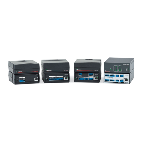
IPL EXP I/O Series • Setup Guide
The Extron IPL EXP I/O Series control system expansion interfaces make it possible to easily expand the number and variety
of ports available in an Extron IP Link
Series control processors. Once configured, these systems allow users to remotely control, monitor, and troubleshoot AV
equipment, including display devices and switchers. All models include an embedded web server. Depending on the model, an
expansion interface can include multiple
bidirectional serial ports, an IR/serial port,
digital I/O, digital I/O with VDC power output,
an Extron eBUS port, or relay ports for use
in applications that require control and
monitoring of multiple devices within a large-
scale AV system.
An eBUS port allows a variety of eBUS
devices to be connected to a single control processor or expansion interface. eBUS devices include an array of button panels as
well as power and signal hubs. eBUS devices are automatically recognized by the control system and can be added or removed
at any time.
In this guide these products are referred to as the "IPL EXP," "EXP," or "expansion interface."
This guide provides instructions for an experienced installer to install a control processor and to create a basic configuration.
Use Extron Toolbelt software to discover and manage the IPCP Pro xi control processor, the IPL EXP I/O expansion interfaces,
and other Extron control products. Configure the control system using Extron Global Configurator
Configurator Professional (GC Professional) or Global Configurator Plus (GC Plus) mode, or program the control processor using
Extron Global Scripter
(GS). The control system integrates seamlessly with Extron GlobalViewer
®
and Extron Control apps for remote control applications. Each IPCP Pro xi control processor supports multiple TouchLink
touchpanel interfaces, Network Button Panels (NBPs), and IPL EXP expansion interfaces over a standard Ethernet network.
Global Configurator and other useful software applications are available at www.extron.com.
Setup Checklist: How to Proceed With Installation
Get Ready
…
Familiarize yourself with the features of the IPL EXP Expansion Iinterface (see
Panel Features
on page 6), and of any IPCP Pro xi Series control processors, TouchLink Pro touchpanels, or button
panels that will be part of the system.
…
Download and install the latest version of the following:
•
Toolbelt software — for discovering the control processor, expansion interface, and other control products on the
network, for managing core settings, and for upgrading firmware when needed
•
Global Configurator (GC) software — for configuring the control system
•
Global Scripter software — for programming the system (as an alternative to GC)
•
GUI Designer software — for designing layouts for Extron TouchLink Pro touchpanels and third-party touch interfaces
•
IP Link Pro device drivers — for use with GC, to make control of other AV devices possible
All are avail able from
…
Obtain network information for the unit from the network administrator. You also need the following details for each
Extron Pro series Ethernet-enabled device:
…
DHCP setting (on or off)
…
Device (IPL EXP, TLP Pro, IPCP Pro or IPL Pro, NBP) LAN IP address
…
AV LAN IP address (for IPCP Pro Q xi models)
NOTE:
If DHCP is on, you do not need the IP addresses and subnet mask.
…
Write down the MAC address of each network interface on each IP Link Pro device to be used.
…
Obtain model names and setup information for devices the system will control.
…
Each expansion interface and each control processor comes with a factory-installed Secure Sockets Layer (SSL) security
certificate. If you intend to install a different SSL certificate, contact your IT department to obtain the certificate or for
instructions on how to obtain one. See "Secure Sockets Layer (SSL) Certificates" in the IPL EXP I/O Series User Guide for
requirements and guidelines regarding SSL certificates. IEEE 802.1X authentication is also supported once enabled (see
"IEEE 802.1X Certificates" in the IPL EXP I/O Series User Guide for details).
Pro xi control system. These expansion interfaces work in combination with IPCP Pro xi
®
www.extron.com
(see
Locating Software, Firmware, and Driver Files on the Extron Website
software running in Global
®
Enterprise (GVE) software
®
Front Panel Features
on page 6,
…
Subnet mask
…
Gateway IP address
Pro
®
Rear
on page 13).
…
Username
…
Passwords
1
Advertisement
Table of Contents

Related Manuals for Extron electronics IPL EXP I/O Series


Summary of Contents for Extron electronics IPL EXP I/O Series
- Page 1 IPL EXP I/O Series • Setup Guide The Extron IPL EXP I/O Series control system expansion interfaces make it possible to easily expand the number and variety of ports available in an Extron IP Link Pro xi control system. These expansion interfaces work in combination with IPCP Pro xi ®...
- Page 2 IPL EXP I/O Series • Setup Guide (Continued) Mount and Cable All Devices … Mount the unit to a rack or furniture (see Mounting on page 4). … Cabling and Features Cable devices to the control processor (see on page 7). … Connect power cords and power on all the devices.
-
Page 3: Network Communication Setup
… If not using GC Professional or GC Plus, use Global Scripter to program the control system as desired. … Program ports on the control processor: • Program each serial, IR/serial, or Ethernet port as needed. • Program relay behavior, digital I/O, and flex I/O settings as needed. …... - Page 4 IPL EXP I/O Series • Setup Guide (Continued) Mounting Securely mount the control system expansion interface and other devices, and attach cables using the wiring section (see Cabling and Features on page 7) as a wiring guide. Optional 1U rack shelves are available for use with all IPL EXP models. Read the instructions and UL guidelines that come with the rack shelf or mounting kit for installation procedures.
-
Page 5: Furniture Mounting
Mounting to rack rails using a ZipClip Furniture mounting Fasten the ZipClip 200 mounting clip to a rack rail using NOTE: The ZipClip is shipped with a set of four wood two rack screws as shown in the diagram below. screws. -
Page 6: Front Panel Features
IPL EXP I/O Series • Setup Guide (Continued) Panels and Locations of Features Location and quantity of LEDs and corresponding connectors vary by model, but the functions and port wiring are identical across models for each port type. Front Panel Features Rear Panel Features IPL EXP S2 00-05-A6-XX-XX-XX... -
Page 7: Power Input
Cabling and Features Attach cables using the following wiring diagrams as a guide. Full details are available in the IPL EXP User Guide. ATTENTION: • Installation and service must be performed by experienced personnel. • L’installation et l’entretien doivent être effectués par du personnel expérimenté. Power Input ATTENTION: •... - Page 8 IPL EXP I/O Series • Setup Guide (Continued) Control, Bidirectional — LAN/PoE (Ethernet) Insert NOTE: The factory configured password TCP/IP Twisted Pair Wires Network Ethernet for this device has been set to the device serial number. Passwords are case sensitive. Performing a Reset to Factory Defaults reset (see Reset Modes: a Brief Summary page 12) sets the password to extron.
- Page 9 Control, Unidirectional — Relays All relays normally open. IPL EXP RIO8 Rear Panels Front Panel Relays • Connect devices for contact control. • Do not exceed a total of 24 V at 1 A for each port. 2 12V24V G 4 12V24V G RELAYS 12 VDC / 24 VDC...
- Page 10 IPL EXP I/O Series • Setup Guide (Continued) Power output (IPL EXP RIO8 only) Rear Panel, IPL EXP RIO8 12 VDC and 24 VDC Power Output 2 12V24V G 4 12V24V G Use these ports to power accessories such as occupancy sensors. Total maximum output is 19 watts, if a PoE+ power supply is used to power the IPL EXP RIO8.
- Page 11 NOTES: • The IPL EXP RIO8 provides a maximum output of 19 watts, combined, for all the DC output ports together. • The IPL EXP RIO8 requires a PoE+ source that provides at least 48 watts (see Power Input on page 7 and see the more detailed information on power input requirements in the IPL EXP I/O Series User Guide). •...
- Page 12 IPL EXP I/O Series • Setup Guide (Continued) Reset Modes: a Brief Summary The expansion interfaces offer the following reset modes: • Run Factory Boot Code: Press and hold the Reset button while applying power to the unit. Keep holding the button down until the Power or Reset LED blinks twice, or for 6 seconds, then release the button.
-
Page 13: Obtaining Control Drivers
Resources Obtaining Control Drivers Extron provides an extensive selection of device drivers available on the Extron website. If the system requires a control driver that is not already available, you can request a new serial (RS-232) or Ethernet driver from Extron. Obtaining Instructions, Information, and Assistance A checklist of basic setup steps is provided at the beginning of this guide. - Page 14 IPL EXP I/O Series • Setup Guide (Continued) Overall Configuration Procedure for the Control Processor and Expansion Interfaces Within Global Configurator Configure the IP settings See Network Network (GC Professional or of the control processor, Communication Setup Communication Setup GC Plus mode): expansion interface, on page 3.
Need help?
Do you have a question about the IPL EXP I/O Series and is the answer not in the manual?
Questions and answers