Table of Contents
Advertisement
Quick Links
KA01112D/06/EN/04.14
71270889
Products
Brief Operating Instructions
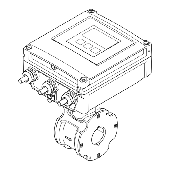
Proline Promag D 400
Electromagnetic flowmeter
These Instructions are Brief Operating Instructions; they are
not a substitute for the Operating Instructions pertaining to
the device.
Detailed information about the device can be found in the
Operating Instructions and the other documentation:
• On the CD-ROM supplied (is not included in the delivery for
all device versions).
• Available for all device versions via:
– Internet:
www.endress.com/deviceviewer
– Smart phone/tablet: Endress+Hauser Operations App
Solutions
Services
Advertisement
Table of Contents

Related Manuals for Endress+Hauser Proline Promag D 400


Summary of Contents for Endress+Hauser Proline Promag D 400
- Page 1 Detailed information about the device can be found in the Operating Instructions and the other documentation: • On the CD-ROM supplied (is not included in the delivery for all device versions). • Available for all device versions via: – Internet: www.endress.com/deviceviewer – Smart phone/tablet: Endress+Hauser Operations App...
- Page 2 Proline Promag D 400 Order code 00X00-XXXX0XX0XXX Ser. No.: X000X000000 TAG No.: XXX000 Serial number www.endress.com/deviceviewer Endress+Hauser Operations App A0023555 Endress+Hauser...
-
Page 3: Table Of Contents
Proline Promag D 400 Table of contents Table of contents Document information ............4 Symbols used . -
Page 4: Document Information
Document information Proline Promag D 400 Document information Symbols used 1.1.1 Safety symbols Symbol Meaning DANGER! DANGER This symbol alerts you to a dangerous situation. Failure to avoid this situation will result in serious or fatal injury. WARNING! This symbol alerts you to a dangerous situation. Failure to avoid this situation can result in WARNING serious or fatal injury. -
Page 5: Basic Safety Instructions
Proline Promag D 400 Basic safety instructions 1.1.4 Symbols for certain types of information Symbol Meaning Symbol Meaning Permitted Preferred Procedures, processes or actions that Procedures, processes or actions that are permitted. are preferred. Forbidden Procedures, processes or actions that Indicates additional information. -
Page 6: Designated Use
Verification for borderline cases: ‣ For special fluids and fluids for cleaning, Endress+Hauser is glad to provide assistance in verifying the corrosion resistance of fluid-wetted materials, but does not accept any warranty or liability as minute changes in the temperature, concentration or level of contamination in the process can alter the corrosion resistance properties. -
Page 7: Workplace Safety
If a plastic transmitter housing is permanently exposed to certain steam and air mixtures, this can damage the housing. ‣ If you are unsure, please contact your Endress+Hauser Sales Center for clarification. ‣ If used in an approval-related area, observe the information on the nameplate. -
Page 8: Incoming Acceptance And Product Identification
Incoming acceptance and product identification Proline Promag D 400 Two device versions are available: • Compact version - the transmitter and sensor form a mechanical unit. • Remote version – the transmitter and sensor are mounted separately from one another. -
Page 9: Product Identification
Proline Promag D 400 Storage and transport • If one of the conditions is not satisfied, contact your Endress+Hauser Sales Center. • Depending on the device version, the CD-ROM might not be part of the delivery! The Technical Documentation is available via the Internet or via the Endress+Hauser Operations App. -
Page 10: Transporting The Product
Storage and transport Proline Promag D 400 • Store in a dry and dust-free place. • Do not store outdoors. • Storage temperature(→ 12) Transporting the product Transport the measuring device to the measuring point in the original packaging. - Page 11 Proline Promag D 400 Storage and transport 5.2.2 Measuring devices with lifting lugs CAUTION Special transportation instructions for devices with lifting lugs ‣ Only use the lifting lugs fitted on the device or flanges to transport the device. ‣ The device must always be secured at two lifting lugs at least.
-
Page 12: Installation
Installation Proline Promag D 400 Installation Installation conditions 6.1.1 Mounting position Mounting location A0023343 h ≥ 2 × DN Installation in down pipes Install a siphon with a vent valve downstream of the sensor in down pipes whose length h ≥... - Page 13 Proline Promag D 400 Installation Installation in partially filled pipes A partially filled pipe with a gradient necessitates a drain-type configuration. A0017063 Orientation The direction of the arrow on the sensor nameplate helps you to install the sensor according to the flow direction.
- Page 14 • Avoid direct sunlight, particularly in warm climatic regions. • Avoid direct exposure to weather conditions. • Protect the display against impact. • Protect the display from abrasion by sand in desert areas. A display protector can be ordered from Endress+Hauser: "Accessories" section System pressure A0015594 Endress+Hauser...
- Page 15 Proline Promag D 400 Installation Furthermore, install pulse dampers if reciprocating, diaphragm or peristaltic pumps are used. Vibrations It is recommended to mount the sensor and transmitter separately. A0016266 3 Measures to avoid device vibrations (L > 10 m (33 ft))
-
Page 16: Mounting The Measuring Device
Installation Proline Promag D 400 6.1.3 Special mounting instructions Display protection ‣ To ensure that the optional display protection can be easily opened, maintain the following minimum head clearance: 350 mm (13.8 in) Mounting the measuring device 6.2.1 Required tools For transmitter •... - Page 17 Proline Promag D 400 Installation A0018060 4 Mounting the sensor Washer Mounting bolts Centering sleeve Seal Arranging the mounting bolts and centering sleeves The device is centered using recesses on the sensor. The arrangement of the mounting bolts and the use of the centering sleeves supplied depend on the nominal diameter, the flange standard and the diameter of the pitch circle.
- Page 18 Installation Proline Promag D 400 Nominal diameter Process connection [mm] [in]5 EN 1092-1 (DIN 2501) ASME B16.5 JIS B2220 2 ½ – A0012171 A0012170 A0010898 A0010827 A0010826 A0012169 A0012168 A0012168 1 = Mounting bolts with centering sleeves 2 = EN (DIN) flange: 4-hole → with centering sleeves 3 = EN (DIN) flange: 8-hole →...
- Page 19 Proline Promag D 400 Installation Mounting the ground cable/ground disks Comply with the information on potential equalization and detailed mounting instructions for the use of ground cables/ground disks (→ 37). Screw tightening torques For detailed information on the screw tightening torques, see the "Mounting the sensor"...
- Page 20 Installation Proline Promag D 400 Post mounting WARNING Excessive tightening torque applied to the fixing screws on plastic housing! Risk of damaging the plastic transmitter. ‣ Tighten the fixing screws as per the tightening torque: 2 Nm (1.5 lbf ft) ø...
- Page 21 Proline Promag D 400 Installation 6.2.5 Turning the transmitter housing TX 20 A0021602 3 mm A0021603 TX 20 A0021830 Endress+Hauser...
- Page 22 Installation Proline Promag D 400 4 mm A0021831 A0021832 Reassembling the transmitter housing WARNING Excessive tightening torque applied to the fixing screws! Damage to the transmitter. ‣ When reassembling, tighten the fixing screws as per the tightening torque: Step Fixing screw...
- Page 23 Proline Promag D 400 Installation Step Fixing screw Tightening torques for housing made of: (see graphics) Aluminum Plastic Main electronics module 1.5 Nm (1.1 lbf ft) Transmitter housing 5.5 Nm (4.1 lbf ft) NOTICE Plug of the smart sensor electronics module connected incorrectly! No measuring signal is output.
-
Page 24: Post-Installation Check
Installation Proline Promag D 400 Step Fixing screw Tightening torque for housing made of: (see graphic) Aluminum Plastic Housing cover 2.5 Nm (1.8 lbf ft) 1 Nm (0.7 lbf ft) ‣ Reverse the procedure to reassemble the measuring device. Post-installation check Is the device undamaged (visual inspection)? ... -
Page 25: Electrical Connection
Proline Promag D 400 Electrical connection Electrical connection The measuring device does not have an internal circuit breaker. For this reason, assign the measuring device a switch or power-circuit breaker so that the power supply line can be easily disconnected from the mains. - Page 26 Electrical connection Proline Promag D 400 Modbus RS485 The EIA/TIA-485 standard specifies two types of cable (A and B) for the bus line which can be used for every transmission rate. Cable type A is recommended. For detailed information about the specification of the connecting cable, see the Operating Instructions for the device.
- Page 27 Proline Promag D 400 Electrical connection Signal transmission 0-20 mA/4-20 mA HART with additional outputs and inputs Order code for Terminal numbers "Output" and "Input" Output 1 Output 2 Output 3 Input 26 (+) 27 (-) 24 (+) 25 (-)
- Page 28 Electrical connection Proline Promag D 400 Remote version 6 5 7 8 4 37 36 42 41 n.c. n.c. 5 7 4 37 42 41 A0020539 7 Remote version terminal assignment Transmitter wall-mount housing Sensor connection housing Electrode cable Coil current cable n.c.
- Page 29 Proline Promag D 400 Electrical connection 7.1.5 Shielding and grounding Modbus The shielding and grounding concept requires compliance with the following: • Electromagnetic compatibility (EMC) • Explosion protection • Personal protection equipment • National installation regulations and guidelines • Observe cable specification (→ 25).
- Page 30 Electrical connection Proline Promag D 400 Where there are large differences in potential between the individual grounding points, only one point of the shielding is connected directly with the reference ground. In systems without potential equalization, therefore, cable shielding of fieldbus systems should only be grounded on one side, for example at the fieldbus supply unit or at safety barriers.
- Page 31 Proline Promag D 400 Electrical connection If measuring device is delivered with cable glands: Observe cable specification (→ 25). 7.1.7 Preparing the connecting cable for the remote version When terminating the connecting cable, pay attention to the following points: •...
-
Page 32: Connecting The Measuring Device
Electrical connection Proline Promag D 400 Sensor Electrode cable Coil current cable 20 (0.79)* 20 (0.79)* 160 (6.30)* 170 (6.69)* 80 (3.15) 70 (2.76) 50 (1.97) 50 (1.97) 18.5 (0.73) 10 (0.39) 6 (0.24) 8 (0.31) ³1 (0.04) A0016489 A0016488... - Page 33 Proline Promag D 400 Electrical connection 7.2.1 Connecting the remote version WARNING Risk of damaging the electronic components! ‣ Ground the remote version: connect the sensor and transmitter to the same potential equalization. ‣ Only connect the sensor to a transmitter with the same serial number.
- Page 34 Electrical connection Proline Promag D 400 5 7 4 37 42 41 A0017446 11 Sensor: connection module 7.2.2 Connecting the transmitter WARNING Housing degree of protection may be voided due to insufficient sealing of the housing. ‣ Screw in the screw without using any lubricant. The threads on the cover are coated with a dry lubricant.
- Page 35 Proline Promag D 400 Electrical connection Supply voltage connection, 0-20 mA/4-20 mA HART and additional outputs/inputs TX 20 + - + - + - + - 23 20 21 26 27 24 25 10 (0.4) A0017268 ‣ Connect the cable in accordance with the terminal assignment (→ 27). For supply voltage: open the shock protection cover.
- Page 36 Electrical connection Proline Promag D 400 Connecting the supply voltage and PROFIBUS DP PH 2 2627 10 (0.4) A0023164 ‣ Connect the cable in accordance with the terminal assignment (→ 27). For supply voltage: open the shock protection cover.
- Page 37 Proline Promag D 400 Electrical connection Connecting the supply voltage and EtherNet/IP PH 2 10 (0.4) A0021356 ‣ Connect the cable in accordance with the terminal assignment (→ 27). For supply voltage: open the shock protection cover. 7.2.3 Ensuring potential equalization...
-
Page 38: Hardware Settings
Electrical connection Proline Promag D 400 A0017516 Connection example in special situations For detailed information on special cases, see the Operating Instructions for the device. • Unlined and ungrounded metal pipe • Plastic pipe or pipe with insulating liner • Pipe with a cathodic protection unit Hardware settings 7.3.1... - Page 39 Proline Promag D 400 Electrical connection Setting the address ON OFF Default Ethernet network settings IP 192.168.1.212 Write protection A0021322 ‣ Set the desired IP address using the corresponding DIP switches on the I/O electronics module. Hardware addressing with the configured IP address is enabled after 10 s.
- Page 40 Electrical connection Proline Promag D 400 The device demands rebooting after 10 s. After rebooting, hardware addressing is enabled with the configured IP address. 7.3.2 Enabling the terminating resistor PROFIBUS DP To avoid incorrect communication transmission caused by impedance mismatch, terminate the PROFIBUS DP cable correctly at the start and end of the bus segment.
-
Page 41: Ensuring The Degree Of Protection
Proline Promag D 400 Electrical connection DIP 3 DIP 1 390 Ω 220 Ω 390 Ω DIP 2 A0023063 14 Terminating resistor can be enabled via DIP switch on the main electronics module Ensuring the degree of protection 7.4.1... -
Page 42: Operation Options
Operation options Proline Promag D 400 Do the cables have adequate strain relief? Are all the cable glands installed, firmly tightened and leak-tight? Cable run with "water trap" (→ 41) ? Only for remote version: is the sensor connected to the right transmitter? ... -
Page 43: Access To The Operating Menu Via The Local Display
Proline Promag D 400 Operation options Access to the operating menu via the local display X X X X X X 19.184 mA 12.5 X X X X X X Language à 20.50 English Deutsch Español Français User ABC_ DEFG... - Page 44 Operation options Proline Promag D 400 8.2.1 Operational display Status area The following symbols appear in the status area of the operational display at the top right: • Status signals – F: Failure – C: Function check – S: Out of specification –...
- Page 45 Proline Promag D 400 Operation options Display area • Icons for menus – : Operation – : Setup – : Diagnostics – : Expert • : Submenus • : Wizards • : Parameters within a wizard • : Parameter locked 8.2.3...
- Page 46 Operation options Proline Promag D 400 8.2.4 Operating elements Keys and meaning Minus key • In a menu, submenu: Moves the selection bar upwards in a choose list. • With a wizard: Confirms the parameter value and goes to the previous parameter.
-
Page 47: Access To The Operating Menu Via The Web Browser
Proline Promag D 400 Operation options 8.2.5 Further information For further information on the following topics, see the Operating Instructions for the device • Calling up help text • User roles and related access authorization • Disabling write protection via access code •... - Page 48 Operation options Proline Promag D 400 Software of the computer Web browsers supported • Microsoft Internet Explorer (min. 8.x) • Mozilla Firefox • Google chrome Recommended operating systems • Windows XP • Windows 7 User rights for TCP/IP settings User rights required for TCP/IP settings (e.g. for changes to IP address, subnet...
- Page 49 Proline Promag D 400 Operation options Device tag Webserv.language English Ent. access code Access stat.tool Maintenance A0017362 Device tag Picture of device 8.3.4 Logging on Access code 0000 (factory setting); can be changed by customer 8.3.5 User interface A0017757-EN Picture of device...
-
Page 50: Access To The Operating Menu Via The Operating Tool
Operation options Proline Promag D 400 Header The following information appears in the header: • Device tag • Device status with status signal • Current measured values Function row Functions Meaning Measured values The measured values of the device are displayed... -
Page 51: System Integration
Proline Promag D 400 System integration System integration For detailed information on system integration, see the Operating Instructions for the device. Cyclic data transmission Cyclic data transmission when using the device master file (GSD). 9.1.1 Block model The block model shows which input and output data the measuring device makes available for cyclic data exchange. - Page 52 System integration Proline Promag D 400 9.1.2 Description of the modules The data structure is described from the perspective of the PROFIBUS master: • Input data: Are sent from the measuring device to the PROFIBUS master. • Output data: Are sent from the PROFIBUS master to the measuring device.
- Page 53 Proline Promag D 400 System integration Selection: control totalizer CHANNEL Value SETTOT Control totalizer 33310 Totalize 33046 Resetting 33308 Adopt totalizer initial setting Factory setting Function block Factory setting: Value SETTOT (meaning) Totalizer 1, 2 and 3 0 (totalizing) SETTOT_MODETOT_TOTAL module The module combination consists of the SETTOT, MODETOT and TOTAL functions: •...
- Page 54 System integration Proline Promag D 400 The selection is made via: "Expert" menu → Sensor → External comp. DI module (Discrete Input) Transmit discrete input values from the measuring device to the PROFIBUS master (Class 1). Selection: device function The device function can be specified using the CHANNEL parameter.
-
Page 55: Commissioning
Proline Promag D 400 Commissioning Commissioning 10.1 Function check Before commissioning the device, make sure that the post-installation and post-connection checks have been performed. • "Post-installation check" checklist (→ 24) • "Post-connection check" checklist (→ 41) 10.2 Switching on the measuring device After a successful function check, switch on the measuring device. -
Page 56: Setting The Operating Language
Commissioning Proline Promag D 400 10.4 Setting the operating language Factory setting: English or ordered local language X X X X X X X 20.50 Main menu 0104-1 Language English Operation Setup Language 0104-1 English à Deutsch Español Français Language 0104-1 Ã... -
Page 57: Protecting Settings From Unauthorized Access
Proline Promag D 400 Diagnostic information Wizard Meaning Display Configure the measured value display Output conditioning Define the output conditioning Low flow cut off Set the low flow cut off Empty pipe detection Configure empty pipe detection (EPD) 10.6 Protecting settings from unauthorized access... - Page 58 Diagnostic information Proline Promag D 400 X X X X X X X X X X X X X X 20.50 S801 Supply voltage Menu Diagnostic list Diagnostics 1 S801 Supply voltage Diagnostics 2 Diagnostics 3 Supply voltage (ID:203) S801 0d00h02m25s...
- Page 60 www.addresses.endress.com...
Need help?
Do you have a question about the Proline Promag D 400 and is the answer not in the manual?
Questions and answers