Table of Contents
Advertisement
Quick Links
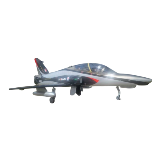
Tomahawk Hawk 100
1:3.5 Scale
PNP
Length: 3.7m, Wing Span 2.85m with Missile Rails
Weight: 63lbs Dry
Fuel Capacity: 5.0L
CONSTRUCTION AND OPERATION MANUAL
Version 1 April 2023
Vne
: Speed to Never Exceed= 170 MPH
Engine 180 to 300
Equipped with HV Servos and should not be operated below 7.4 volts
This is a LTMA Aircraft
3481 State Road 419 • Winter Springs, FL 32708 USA
tel. 407-327-6333 • fax. 407-327-5020
Advertisement
Table of Contents

Related Manuals for BVM Tomahawk Hawk 100


Summary of Contents for BVM Tomahawk Hawk 100
- Page 1 Tomahawk Hawk 100 1:3.5 Scale Length: 3.7m, Wing Span 2.85m with Missile Rails Weight: 63lbs Dry Fuel Capacity: 5.0L CONSTRUCTION AND OPERATION MANUAL Version 1 April 2023 : Speed to Never Exceed= 170 MPH Engine 180 to 300 Equipped with HV Servos and should not be operated below 7.4 volts This is a LTMA Aircraft 3481 State Road 419 •...
-
Page 2: Table Of Contents
The Orange arrows point to where this goes............... 11 Mounting The Vertical Fin ...................... 11 NOTE: You can apply some BVM Dry Lube on the carbon tubes to ease installation... 11 Ventral Fin Mounting ......................12 Turbine Mounting ........................13 Fuel Pump and ECU Mounting .................... - Page 3 Control Surface Deflections and Expo Settings ..............19 Connecting RX wires ......................19 IX20 and Transmitter File ....................20 Gyro Sense..........................20 Takeoff ........................... 21 Trim ..........................21 Slow Flight Testing ......................21 Practice Approaches ...................... 21 Landing ........................... 21 Pilot’s Notes: ........................22 BVM ©2023 4/2023...
-
Page 4: Pnp
Hawk 100 Introduction Thank you for purchasing the Tomahawk Hawk 100 PNP Only a small amount of work is required to complete the assembly of your Hawk 100. This manual contains instructions for safety, operation and maintenance. It is essential to read and follow all of the instructions and warnings in the manual. -
Page 5: Bvm Products
Hawk 100 BVM Products Received with the Instruction Package that is sent from BVM Hawk 100 Assembly and Operation Manual Recommended Accessories Available at BVMJets.com You may have some of these products in your shop, but if not, refer to this list. -
Page 6: Required Tools
After reading this entire manual, get familiar with the major kit components. Note: Damaged parts must be reported to BVM within 7 days of receiving your kit. Become familiar with the work completed at the factory. It is important that you inspect and approve this work now. -
Page 7: Joining The Aft Fuse To The Forward Fuse 6 Pin System
Then install the 2 front duct screws. use a small amount of Z-42 on these as well. Note: The fuse is a tight fit and will squeeze a small amount when joining the 2 halves. BVM ©2023 4/2023... -
Page 8: Fuel System Check
Unscrew the Aluminum cap and pull the assembly out. At this point you will be able to Safety wire the clunk tubing to the cap and the Clunk. The BVM demo Hawk uses all stock tubing supplied with the Aircraft. BVM ©2023 4/2023... -
Page 9: Option For The Fuel System
Hawk 100 Option for the Fuel System BVM decided to use a length of Brass tubing between our Cap and Clunk. This was the only mod we made to the system Secure your tubing to your UAT with Safety Wire or your favorite method. -
Page 10: Mounting The Vent
Hawk 100 Mounting the Vent The BVM Hawk has the vent mounted on the fuse just behind the equipment tray. Your Hawk will come with wood spacer that will get glued into the fuse. After gluing in place drill a hole through the fuse and install the Overflow fitting. -
Page 11: Mounting The Stabilator
Stabilator in place. Apply a small dab of Z-42 Loctitie to each bolt. The Carbon Doubler sits on top of the Stabilator. Your Stabilator is now mounted to the Aircraft Note: Check these periodically for tightness BVM ©2023 4/2023... -
Page 12: Stabilator Linkage
There are a total of 3 bolts you need to tighten to secure it in place. The Orange arrows point at the access holes. NOTE: You can apply some BVM Dry Lube on the carbon tubes to ease installation. BVM ©2023... -
Page 13: Ventral Fin Mounting
Hawk 100 Ventral Fin Mounting Remove the bottom Hatch; this has 4 screws holding it in place. The Ventral fins are secured by 3 self tapping screws per side. Once done re install the bottom hatch cover. BVM ©2023 4/2023... -
Page 14: Turbine Mounting
Hawk 100 Turbine Mounting The BVM Demo Hawk uses a T-22 Turbine with 49lbs of thrust. On our demo model we had to make spacers to fit between the rails. You may or may not have to do this. Center your engine L/R and Up and Down in the Tail pipe. - Page 15 Aileron as well as the cover itself. Using QT- Poxy secure the cover to the Aileron. One side completed and ready to move to the Flap Hinge covers. The other wing will be the same steps. BVM ©2023 4/2023...
-
Page 16: Mounting The Flap Fairings
Pylon. Note: The screws to mount the Drop tanks face the wing tip. Mounting the Missile Rails The Missile rails are held to the tip of the wing with 2 self tapping screws in each rail. BVM ©2023 4/2023... -
Page 17: Mounting The Missiles
The clamping Brackets are at the leading edge and trailing edge of the wing. A 9/64 Ball driver is used to tighten the clamps. There is also a servo connection block that joins all the wires. BVM ©2023 4/2023... -
Page 18: Center Of Gravity
Center of Gravity 12.2 to 12.7 inches aft of the leading edge of the wing at the wing root. The BVM demo model is flying at 12.7”. This CG was done with the UAT full. We didn’t add any weight to our demo model to achieve proper CG. -
Page 19: Electric Gear And Brake Controller
The Gear controller does need to be turned off between flights for it to work properly.BVM recommends The use of a switch to turn it On and OFF between flights Note: The Gear motors are sensored and requires that all gear be hooked up for the doors to work properly. -
Page 20: Control Surface Deflections And Expo Settings
” Connecting RX wires The wires are labeled from the factory. If you are using the IX20, the program is available from BVM. Follow the chart below to connect the servos. Spektrum 20 Channel Receiver Hook Up RX Port Throttle... -
Page 21: Ix20 And Transmitter File
Check also the correct gyro action in the roll and pitch axes. It is BVM’s practice for a first “gyro assisted flight”, to take-off with the transmitter 3 position gyro assigned switch in the “OFF” position. Climb to a safe altitude and trim the model for the various flight configurations and speed. -
Page 22: Takeoff
Landing the Hawk 100 is like most jets, “power on” during the approach. It is best to land slightly nose high, touching on the main wheels first, then retard the throttle to idle and apply the wheel brakes. BVM ©2023 4/2023... -
Page 23: Pilot's Notes
Hawk 100 Pilot’s Notes: BVM ©2023 4/2023...
Need help?
Do you have a question about the Tomahawk Hawk 100 and is the answer not in the manual?
Questions and answers