Table of Contents
Advertisement
Quick Links
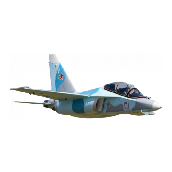
BVM PNP Yak 130
CONSTRUCTION AND OPERATION MANUAL
1:4.85 Scale
Length: 94", Wing Span: 79" with Missile Rails
Weight: 32-34lbs Dry
Fuel Capacity: 4.0L, Smoke Capacity: 2.5L
Copyright 2016
Version 1.3
June, 2016
Vne
: Speed to Never Exceed= 175 MPH
Limit Engine Thrust to 36 lbs.
Equipped with HV Servos and should not be operated below 7.2 volts
For addendums and accessory products see:
BVMJets.com/Pages/kits/YAK130NEWS.htm
3481 State Road 419 • Winter Springs, FL 32708 USA
tel. 407-327-6333 • fax. 407-327-5020
K7900
BVM-2016
Advertisement
Table of Contents

Subscribe to Our Youtube Channel
Related Manuals for BVM Yak 130


Summary of Contents for BVM Yak 130
- Page 1 BVM PNP Yak 130 CONSTRUCTION AND OPERATION MANUAL 1:4.85 Scale Length: 94”, Wing Span: 79” with Missile Rails Weight: 32-34lbs Dry Fuel Capacity: 4.0L, Smoke Capacity: 2.5L Copyright 2016 Version 1.3 June, 2016 : Speed to Never Exceed= 175 MPH Limit Engine Thrust to 36 lbs.
-
Page 2: Table Of Contents
YAK 130 Contents Introduction ..........................3 Disclaimer ..........................3 BVM Products ........................4 Recommended Accessories ....................4 List of Adhesives/Lubricants ....................5 Available Options ......................... 5 Required Tools ........................5 Unpacking ..........................6 ... - Page 3 YAK 130 Radio Equipment Installation ....................44 Receiver ..........................44 Gyro Mount ........................45 Central Control Unit Instructions .................... 46 Light Connections ....................... 48 Mounting RX Batteries ....................... 49 Mounting ECU Battery ......................49 ...
-
Page 4: Introduction
Notice: Do not use with incompatible components or alter this product in any way outside of the instructions provided by BVM, Inc. The BVM Yak 130 has been designed and flight tested around 140N class engines. Damage to the aircraft may result from exceeding this thrust limitation (36 lbs). -
Page 5: Bvm Products
YAK 130 BVM Products Received with the Instruction Package that is sent from BVM Laser Cut Ply U.A.T. Tray Laser Cut Ply Gyro Mount #2 Button Head Screws Carbon “L” Bracket #10 Screws to replace Turbine Mounting Screws 8” Tie Wraps for Equipment Board 4”... -
Page 6: List Of Adhesives/Lubricants
BVM #5784 BVM Dry Lube BVM #1947 BVM Thin Lube for “O” Rings BVM #1945 The BVM Thin “O” Lube is the only lube that should be used for any pneumatic system. Thin Lube and Applicator Available Options Available at BVMJets.com Warbirds 15”... -
Page 7: Unpacking
After reading this entire manual, get familiar with the major kit components. Note: Damaged parts must be reported to BVM within 7 days of receiving your kit. Become familiar with the work completed at the factory. It is important that you inspect and approve this work now. -
Page 8: Joining The Aft Fuse To The Forward Fuse 4 Pin System
YAK 130 Joining the Aft Fuse to the Forward Fuse 4 Pin System See next page for 6 Pin System. Sequence: Test join the 2 fuse sections. Then separate the aft and forward sections. Install the Inlet Ducts. - Page 9 YAK 130 For Post January 2016 models- 6 Pin System Install (4) Aluminum Joiner Pins at the 12, 3, 6, and 9 o’clock positions of the Aft Fuse section. See previous page photos. Apply Z-42 to each 3mm x13mm, then install from the rear into the aluminum pins.
-
Page 10: Inlet Duct Installation
YAK 130 Inlet Duct Installation This is the most challenging part of the assembly process. Some modeling skill and experience will come in handy. Use #80 grit to sand the entire outside of the inlets to remove all sharp splinters and edges of the carbon cord and fiberglass. - Page 11 YAK 130 Use medium Zap-A-Gap to glue these lap seams together if needed. They might have gotten jarred during packing and shipping. Inspect the Inlet Cowl Lip; use a Dremel rotary rod grinder (#RF6C) to remove excess resin globs from the fuselage inlet lip that might interfere with the inlet duct fit.
- Page 12 YAK 130 Place the inlet ducts into the Fwd fuse section and tape them to the fuse in 3 or 4 places.. Right Inlet Shown Left Inlet Shown Remove the (6) 2.5mm x 14mm SHCS from the Inlet retaining former in the Aft fuse.
- Page 13 YAK 130 Use a pointed awl to align the holes in the inlet plywood bracket to those in the fuse former. With the awl in one hole set, install (2) 2.5mm x 14mm SHCS per duct side. Remove the awl and install the remaining SHCS.
- Page 14 YAK 130 Install the (4) 3mm x 14mm SHCS from the forward side of the fuse half. Access is through the Cockpit opening. Use a drop of Z-42 on each SHCS. NOTE: Both air storage tanks have been pushed aft at this time to get access to the bolts at the 3 and 9 o’clock positions.
-
Page 15: Spot Gluing The Inlet Ducts Into The Fuse
YAK 130 Spot Gluing the Inlet Ducts into the Fuse (See also next page.) NOTE: The aft end of the Inlet Ducts are temporarily held together with (2) #64 rubber bands. Use clothes pins or small clamps to hold for cure. -
Page 16: Alternate Method For Gluing Inlets
YAK 130 Alternate Method for Gluing Inlets NOTE: The Aft ends of the Inlet Duct are held together with #64 rubber bands. For a permanent bonding of the (2) Inlet Ducts, Use Aeropoxy. . Inject a small amount between the aft center flanges of the duct.. -
Page 17: Routing Servo Wires, Light Wires, And Air Lines
YAK 130 Bottom It will be necessary to trim the bottom and top Inlet center web to allow room for the turbine F.O.D. screen. A 90 Dremel tool with a drum sander works well. Routing Servo wires, Light wires, and Air Lines... -
Page 18: Air Lines
Air Lines Unwrap the bundle of Air Lines and route them forward and through the former as shown. Install (2) of the Large BVM “O” Clips (part # PA-SR-0026) at the locations shown in the photo. BVM ©2016... -
Page 19: Connect The Air Lines To The Air Valves
YAK 130 Use 4” Tie Wraps and BVM “O” Clips to secure the Air Lines. Continue to route forward as shown. Connect the Air lines to the Air Valves Connect the clear “BRAKE” line to the top of the Brake Air Valve. Use the 2mm Air Line Collars provided to secure the Air Line to the Valve. -
Page 20: Connect The Air Line 3 Way/4 Way Blocks
YAK 130 Connect the Air Line 3 way/4 way Blocks NOTE: Use the 2mm Air Line Collars to secure connections. When installing the Air Lines, place the black “DOOR CLOSED” line onto the “4 way block” with the other black “DOOR CLOSED”... - Page 21 YAK 130 Route all the wire sets forward through the fuse as shown. Use the “O” Clip installed during the Air Line portion to secure to the fuse side wall. Disconnect the #4 circuit board from the (4) wire bundle.
- Page 22 YAK 130 Plug the (4) wire bundle into the #4 circuit board. Disconnect the #2 circuit board and route the wires as in the previous step. Continue routing the #2 wires through the next former as pointed to by the pencil in the photo.
- Page 23 YAK 130 Locate and connect the Nose Gear Landing Lights wire to the matching JST RCY connector coming off the #2 circuit board. Locate the single #4 circuit board and route the wires using the same methods as the previous wire sets.
-
Page 24: Servo Wires
Untie the bundle of servo wires and route forward as shown. Use 4” tie wraps to hold the wires neatly in place. Add a 12” piece of Wire Loom (BVM# PA- SR-0026) to cover the wires at the front cockpit area. - Page 25 YAK 130 Route the wires under the former containing the Central Control Module to allow connection to your receiver. A 12” piece of Velcro works great to bundle the wires and air lines. This keeps them out of the way of the cockpit.
-
Page 26: Fuel/Smoke Tank
YAK 130 Fuel/Smoke Tank NOTE: Please read Cockpit installation portion of this manual to have an understanding of the clearances for the tubing. Place the Main Fuel Tank into position. Place the Smoke Tank into the space above the Main Tank. Make sure to identify the overflow vent tube from the clunk tube. - Page 27 YAK 130 Connect the Smoke Tanks overflow/vent tubing to the aft Flush Mount fitting. Connect the Clunk line tubing (the tube with the blue tubing) with the Festo fitting from the smoke pump. Use enough tubing to allow clearance for the Cockpit Tub.
-
Page 28: Cockpit Installation
YAK 130 Install the BVM U.A.T. (follow the U.A.T. instructions) and the turbine Fuel Pump onto the BVM supplied tray. Connect the Main Fuel Tank Tubing to the U.A.T. Connect the U.A.T. to the Fuel Pump. Make sure the retracted Nose Wheel does not interfere with either tubing. - Page 29 YAK 130 Test fit the Cockpit to make sure the fuel lines do not interfere. Make any adjustments necessary to fuel line placement for a proper fit. There is a wood block that captures the front edge of the cockpit tub.
-
Page 30: Vertical Fin And Rudder
YAK 130 Vertical Fin and Rudder The Yak 130’s Fin/Rudder is very easy to remove for transit purposes. Just (2) screws and (2) electronic plugs are used to mount/release them. Use a 9/64 hex head wrench to loosen/tighten the screws. -
Page 31: Stab Installation
YAK 130 Stab Installation Remove the access cover on the bottom of the fuse below the Stab area. The access cover is held in place with (4) Phillips Head Screws. Insert the Stab tube, aligning the slot on the tube with the pin in the receptacle. -
Page 32: Turbine Installation
YAK 130 Turbine Installation Remove the Arch Brace shown in the photo. It can be re-installed after the engine is mounted. Drill a small hole (1/16”-3/32”) on each side of the main gear door formers for accidental fuel over flow exit points. - Page 33 C.A. to toughen the threaded holes in the plywood. To install the turbine ECU, BVM used the space on the UAT mount tray. It is convenient and does not interfere with the cockpit tub.
- Page 34 NOTE: This set-up requires the Cockpit Tub to be removed for fueling and starting engine. See Alternative System on following Page. At BVM, we like to run the engine with the System Analyzer/GSU always handy. The advantage of this is that you can always access the internal diagnostics when needed.
-
Page 35: Alternate Equipment Service Location
YAK 130 Alternate Equipment Service Location With Speed Brake Hatch Removed Note: Spacer blocks under Turbine mount are not required for production models. The Air Fill Valve along with the Air Pressure Gauge and Receiver On-Off Switch can be relocated to the engine area for an alternative start-up operation. -
Page 36: Wing Prep And Installation
YAK 130 Wing Prep and Installation Flap Install Match up the Wing with the correct Flap. The large control horn is the inside hinge and control horn. The small horn is a hinge only. Remove the (2) 2mm SHCS and (2) 5mm lock nuts from the wing side of the Flap hinge. - Page 37 YAK 130 Install the (2) 2mm SHCS and (2) 5mm lock nuts. DO NOT OVER TIGHTEN, the flaps need to move freely. Remove the 2mm SHCS and 5mm lock nut from the top of the Control Horn. Insert the 2mm SHCS through the ball link and then through the control horn.
-
Page 38: Flap Actuator Fairings
YAK 130 Flap Actuator Fairings Tape in place the (2) large (6”) and (2) small (3”) Flap Actuator Fairings. The leading edge of the small fairing is centered over the leading edge of the Flap. The trailing edge of the large fairing is located by a 1/16”... - Page 39 YAK 130 Install the small fairings using the small Phillips screws supplied. Tape off the hinges, and control rod to protect them. Trim the small fairing to allow it to move properly. Remove small amounts and test repeatedly until a desired movement is achieved.
-
Page 40: Wing Tip Missile Rails
YAK 130 Use Model Masters (or similar) paint to color the screw heads and notches in fairings. Also touch-up the Aileron metal rod and servo arm. Wing Tip Missile Rails Match up the corresponding Missile Rail to the corresponding Wing. The Missile Rails should be scribed with and L or R to indicate sides. -
Page 41: Wing Installation
YAK 130 Wing Installation Slide the wing partially into the wing tubes and connect the Aileron, Flap, and Light wires. Use servo clips or tape to secure the wires together. Push the wing flush with the fuselage and tighten the (2) 9/64 SHCS on each wing. -
Page 42: Main Wheels And Brakes
YAK 130 Main Wheels and Brakes NOTE: The Tires on the Yak 130 are not inflatable. NOTE: Periodic preventative maintenance of all landing gear systems is the modelers challenge to keep things from coming loose. NOTE: The wheels should be removed so that the axles and bushings can receive lubrication. - Page 43 Apply BVM’s “Super Lube” to the axle and bushings in both sides of the wheel. Apply a thin finger wipe of BVM “O” lube to the inside surface of the brake drum. A very small amount helps to keep the brakes from grabbing.
-
Page 44: Nose Wheel
Nose Wheel for similar lubrication on the axle and bushings. Use the BVM Thin Lube for “O” Rings kit (BVM# 1945) on the strut cylinders. The BVM Thin “O” Lube is the only lube that should be used for any pneumatic system. -
Page 45: Radio Equipment Installation
YAK 130 Radio Equipment Installation Receiver Route the Central Controller’s wires under the plywood former as shown. This allows the RX to be mounted to the former. Apply a Zap finish to the plywood former to prepare the surface for adhesive backed Velcro. -
Page 46: Gyro Mount
Apply a Zap finish to the top of the Gyro Mount. A Demon Aero Cortex Gyro is shown here. BVM includes additional instructions with this unit. Glue the Gyro Mount to the fuse and the front side of the front Nose Gear former as shown. -
Page 47: Central Control Unit Instructions
C-1) Short press- Tap this button and the screen will display “PSI”, “V” (Voltage) and “RPM”. The corresponding LED of each function will be on when it is displayed. Note: BVM does not use the RPM function of this controller. C-2) Long press- Holding this button down when “PSI” is displayed will enter the “Pressure Loss Protection Setup”. - Page 48 YAK 130 C-3) Long press- Holding this button when “V” is displayed will enter the “gear door time- lapse setup”. Increase 1 second with each press, max setting is 15s. Function: The gear door time lapse setting indicates to the nose wheel steering servo when to be on or off.
-
Page 49: Light Connections
YAK 130 Green LED: corresponds to Landing gear Fail-Safe (F/S). When this function is on (Green LED), height protection is activated. If the airplane is sitting ground level while a retracting command is sent from transmitter, the controller will not execute this command until the plane flies up to an altitude of set value. -
Page 50: Mounting Rx Batteries
YAK 130 Mounting RX Batteries NOTE: The prototype Yak utilized (2) Duralite EXB 3000 mAh packs, one is located in the nose section, the other next to the Nose Gear Retract Unit. Use sticky back Velcro and Velcro strap to mount the batteries as shown. -
Page 51: External Scale Details
YAK 130 External Scale Details Use these photos to locate the (4) external scale detail parts.. Glue on with a thick C.A.. BVM ©2016 Mar. 23, 2016... -
Page 52: Center Of Gravity
YAK 130 Center of Gravity The C/G is 6” aft of the leading edge fairing on the fuselage as shown. The C/G is also located by the factory with ink on the side of the wing fairing. Drill a 1/16” hole on the bottom side of the wing root fairng at the 6”... -
Page 53: Flush Mount Vent And Overflow System
Check also the correct gyro action in the roll and pitch axes. It is BVM’s practice on a first gyro assisted flight to take-off with the transmitter 3 position gyro assigned switch in the “OFF” position. Climb to a safe altitude and trim the model for the various flight configurations and speed. -
Page 54: Control Surface Deflections And Expo Settings
10% / 8% / 8% 0% / 0% 1.25” 1” 3/4” Note: The BVM Demo plane is setup using the following Expo percentages. Positive values are used on Spektrum and JR radios, Futaba uses negative. Flap Deflections Flaps Take Off 3/4”... -
Page 55: Connecting Rx Wires
Brake DX18 and DX18QQ Transmitter File The BVM Demo models are setup on Spektrum DX18 transmitters. The file included on the SD card has all the mixes, rates, expos, and settings done for you. Setting the sub trim and travel adjustment must be accomplished by the modeler for the specific aircraft. -
Page 56: First Flight Profile
“OFF” position. Takeoff Begin the takeoff roll by slowly advancing the throttle. The YAK 130 will lift off with very little up elevator. It there is a crosswind, hold a small amount of aileron into the wind and apply opposite rudder as required. -
Page 57: Slow Flight Testing
The use of the smoke pump will consume more mAh per flight. BVM is synonymous with “Success Jets.” It is very important to us that you are successful with our products. This extensive manual reflects our sincerity. As always, your comments and suggestions on BVM products are appreciated. -
Page 58: Pilot's Notes
YAK 130 Pilot’s Notes: BVM ©2016 Mar. 23, 2016...
Need help?
Do you have a question about the Yak 130 and is the answer not in the manual?
Questions and answers