Table of Contents
Advertisement
Quick Links
Advertisement
Table of Contents

Related Manuals for BVM Bandit arf


Summary of Contents for BVM Bandit arf
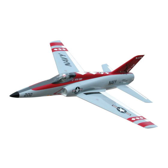
- Page 1 Assembly and Operation Instructions Manual Limit Maximum Speed to 200 MPH and Max Thrust to 20lbs BVM © 2009 3481 State Road 419 • Winter Springs, FL 32708 USA tel 407-327-6333 • fax 407-327-5020 Please visit www.BVMJets.com for the latest Bandit ARF updated information.
-
Page 2: Table Of Contents
DISCLAIMER ...............................1 A PERFECT FINISH? ............................2 COLOR BLEED..............................2 THE SUN AND HIGH SKIN TEMPERATURES....................2 FINISHING YOUR ALL WHITE BANDIT ARF .....................2 GUARD AGAINST SCRATCHES AND DENTS ....................3 WAX THE COLOR PAINTED MODEL BEFORE ASSEMBLY ................3 CONTROL SURFACE FLEX HINGE TUNE-UP....................3 PERMA-GRIT AND SOME OTHER USEFUL TOOLS ..................4... - Page 3 SWEPT FIN ..........................27 INSTALLING THE SWEPT FIN RUDDER SERVO ...................27 RUDDER CONTROL HORN..........................28 CANOPY AND ENGINE COMPARTMENT HATCHES .............29 LAPPING THE JOINTS FOR AN IMPROVED FIT ....................29 ENGINE HATCH ..............................30 CANOPY HATCH...............................31 FUSELAGE SPREADER ...........................33 BELLY HATCH..............................34 FUSELAGE ..........................35 INLETS................................35 NOSE GEAR STEERING SERVO TRAY, PUMP MOUNT, F2, AND F3 ............36 NOSE GEAR DOOR ............................37 NOSE GEAR DOOR AIR CYLINDER........................39...
-
Page 4: Assembly And Operation Manual
Assembly & Operation Manual INTRODUCTION This instruction package is extensive, not because the model is difficult to build but because it represents a thorough effort to make the Bandit ARF assemble easily and allow the factory prototypes to be duplicated. WARNING This model is designed to safely operate with model turbine engines in the 13-20lb thrust range. -
Page 5: A Perfect Finish
A PERFECT FINISH? Well-almost. The color finish on the BVM Bandit ARF model is applied utilizing both paint in and out of the mold processes. Sometimes, because of human error, the paint is patched and polished. The resulting appearance is better than 95% of what is accomplished by modelers in their shops and better than competitive ARFs on the market. -
Page 6: Guard Against Scratches And Dents
Always support these structures on clean soft foam rubber. We have found that auto body fender stands (available at auto paint and parts suppliers) are very helpful in supporting and assembling models such as the Bandit ARF. WAX THE COLOR PAINTED MODEL BEFORE ASSEMBLY It is a good practice to apply (2) coats of automotive wax (such as Meguiars) to all of the painted surfaces before beginning to work on the model. -
Page 7: Perma-Grit And Some Other Useful Tools
Assembly & Operation Manual PERMA-GRIT AND SOME OTHER USEFUL TOOLS Perma-Grit tools are sold in the USA by BVM. These are very high quality, tungsten carbide grit abrasive tools that will make modeling easier. TOOL LIST 2-56 tap Dremel #409 cut-off discs and mandrel... -
Page 8: General Assembly Techniques
Bandit ARF. TRIAL FITTING PARTS BVM makes every attempt to insure that the parts in our kits have the best possible fit. However, due to manufacturing tolerance accumulation, some parts may fit a little tight. Always trial fit parts with mating parts and if necessary adjust the part perimeter with Perma-Grit hand tools. -
Page 9: Glue, Zap And Bvm Aeropoxy
Low quality glues deteriorate with time and could render the model unsafe. For extremely high stress areas, such as the wing and tail mounting former to fuselage joints, BVM has made available a thixotropic, slow cure, aerospace grade, 2-part epoxy system that has been dubbed “AeroPoxy.”... -
Page 10: Molded Carbon Fiber Parts
Warning!! Damage to the transmitter module may result if the radio system is used on the bench for an extended amount of time with the antenna down. BVM uses a “Shop module” which is used for aircraft setup; this module never leaves the shop. -
Page 11: Tires And Control Linkages
AXLE FLAT SPOT Disassemble the wheel and brake from the strut. Use a Dremel with a #409 cut off disk to make a flat spot on the axle. BVM © 2009 K5300-Current_manual-090808.doc Page 8 12/2/2009... -
Page 12: Tire Screws
Before tightening the tire screws, apply a drop of blue Thread Locker to the threaded holes. This prevents the screws from backing out under the vibrations of braking. Carefully tighten the screws, avoid stripping the threads. BVM © 2009 K5300-Current_manual-090808.doc Page 9 12/2/2009... -
Page 13: Lubing The Brakes And Axles
Assembly & Operation Manual LUBING THE BRAKES AND AXLES Apply a large drop of Super O Lube BVM #5779 to the brake drum surface of the wheel. Wipe this in until an even coat is distributed; apply an equal amount to both main wheels. At this time apply axle grease BVM #5784 to the wheel bushings and reinstall the wheels onto the struts as described earlier. -
Page 14: Wings
Crate) foam. Cut the foam to cover the work area; even allow it to roll over the edges of the table. BVM uses the type with many raised and lowered points; these points help to protect the model from wayward nuts and bolts. This simple precautionary step will minimize hangar rash. -
Page 15: Flexplates
4-40 tap for the (4) 4-40 x ½” SHCS. Install the flex plates into the wing using four 4-40 x ½” SHCS. It is necessary to remove a little of the F/G flange for clearance of the driver. BVM © 2009 K5300-Current_manual-090808.doc Page 12 12/2/2009... -
Page 16: Aligning The Main Gear
The clear brake line is also adjacent the front side of the strut and over the round brass frame cross member of the retract unit. BVM © 2009 K5300-Current_manual-090808.doc Page 13 12/2/2009... -
Page 17: Installing The Wing Controls
(1) inch very slightly to allow a spinning action to help guide through formers and ribs. Use masking tape to temporarily attach the Nyrod to the servo connector, pull gently through the structure to avoid damage to the servo lead. BVM © 2009 K5300-Current_manual-090808.doc Page 14 12/2/2009... - Page 18 (included in the nose gear door package) with a flat point ground on the tip. Use a belt sander to grind an angled flat point; the sharp edges will act as the drill cutters. BVM © 2009 K5300-Current_manual-090808.doc Page 15...
-
Page 19: Aileron Control Horns
Always scuff the gluing surfaces, and clean the clevis hole with a sharp 1/16” drill prior to installation. Use a 1/16” carbide cutter BVM #2142 to make a slot in the control surface as indicated by the pen mark. Set the carbide cutter to the appropriate depth by comparing it to the length of the control horn’s base. - Page 20 Pull the surrounding tape from the control horn and clean glue residue from the painted surface. Use a long piece of masking tape stretched over the center of the control horn to hold in position while the AeroPoxy cures. BVM © 2009 K5300-Current_manual-090808.doc Page 17 12/2/2009...
-
Page 21: Flap Servos
Drill random 1/16” holes in the maple blocks for better glue adhesion. Use #80 grit to sand the wing skin in preparation for the flap servo mounting blocks. BVM © 2009 K5300-Current_manual-090808.doc Page 18 12/2/2009... -
Page 22: Flap Control Horns
The music wire slips though the laser cut hole. Use AeroPoxy to hold the control horn in place. A strip of masking tape can be used to hold the ply locator while glue cures. BVM © 2009 K5300-Current_manual-090808.doc Page 19 12/2/2009... -
Page 23: Servo Covers And Gear/Strut Covers
Wing FWD Pin This carbon fiber leading edge pin should be installed on Bandit ARF’s that are intended for high performance i.e. 19 + pound thrust engines. This pin and receptacle should be checked for security following a hard landing. - Page 24 CF part to the inside fuse skin while assuring that the wing leading edge is centered. Remove the wing and apply Aeropoxy to the CF part to secure it to the fuse. BVM © 2009 K5300-Current_manual-090808.doc Page 21 12/2/2009...
-
Page 25: Stabilizers
Carbon tube with a cotton Q-tip. Carefully insert stab mount tube into the aluminum bracket allowing for the designed-in stab anhedral. During final assembly, snug the setscrews to retain the stabs. BVM © 2009 K5300-Current_manual-090808.doc Page 22 12/2/2009... - Page 26 Assembly & Operation Manual Note: As of September 2009 the tubes in the Bandit ARF were changed from carbon fiber tubes with a steel insert, to steel tubes with a carbon fiber insert. For the latter, test fit the carbon fiber rod into the steel tube,...
- Page 27 A 6-32 bolt is used to secure the front pin. NOTE: This procedure is repeated for both stabs and the vertical fin. Setscrews tightened through holes in bottom of the fuselage. BVM © 2009 K5300-Current_manual-090808.doc Page 24 12/2/2009...
-
Page 28: Installing The Elevator Servos
Cut the slot for the servo arm as marked on the bottom skin. Adjust for proper clearance once the servo is installed and linkage connected. Drill the (4) servo mounting holes with a 1/16” bit. BVM © 2009 K5300-Current_manual-090808.doc Page 25 12/2/2009... -
Page 29: Elevator Control Horns
Apply AeroPoxy into the slot and the holes on the base of the of the control horn. Push the scuffed control horn into the surface, and wipe the excess glue away leaving a small fillet. BVM © 2009 K5300-Current_manual-090808.doc Page 26... -
Page 30: Swept Fin
Use a Perma-Grit file and a 1/16” cutter to open the servo arm slot in the vertical fin skin. Open this up to the marked line and adjust for proper clearance once the servo is installed and linkage connected. BVM © 2009 K5300-Current_manual-090808.doc Page 27 12/2/2009... -
Page 31: Rudder Control Horn
Pull the surrounding tape from the control horn and clean and glue residue from the painted surface. Use a long piece of masking tape stretched over the center of the control horn to hold in position while the AeroPoxy cures. BVM © 2009 K5300-Current_manual-090808.doc Page 28 12/2/2009... -
Page 32: Canopy And Engine Compartment Hatches
Assembly & Operation Manual CANOPY AND ENGINE COMPARTMENT HATCHES BVM designs our jets for easy access to the engine, fuel system, and electronic components from the topside of the model. This design philosophy minimizes having to flip the model upside down for simple servicing items;... -
Page 33: Engine Hatch
While holding the engine hatch in place use a fine point marker to trace the location of the receptacle hole. Drill these receptacle holes small, then use a Perma-Grit round file to adjust the size and location necessary to achieve a proper fit. BVM © 2009 K5300-Current_manual-090808.doc Page 30 12/2/2009... -
Page 34: Canopy Hatch
Trim the (4) hooks as shown make (2) left and (2) rights. Install one untrimmed hook in the front. As before, maintain side-to-side alignment. BVM © 2009 K5300-Current_manual-090808.doc Page 31 12/2/2009... - Page 35 Drill the hole through the canopy hatch into the 1/8” ply plate. Drill and tap ¾” x ¾” maple block for the rear ¼-20 nylon hold down bolt. Glue in place on the 1/8” ply plate using the nylon bolt for proper alignment. BVM © 2009 K5300-Current_manual-090808.doc Page 32 12/2/2009...
-
Page 36: Fuselage Spreader
Remove the hatch and line up the wood support in a location that does not interfere with normal maintenance procedures. Drill the fiberglass flange and wood support stick with a 1/16” drill. Install the wood support using #2 x 3/8” button head screws. BVM © 2009 K5300-Current_manual-090808.doc Page 33 12/2/2009... -
Page 37: Belly Hatch
Use a 1/16” bit to drill (6) evenly spaced holes through the fiberglass hatch and plastic mounting frame. Finish the fiberglass hatch using a clearance drill for the (6) button head attachment screws. BVM © 2009 K5300-Current_manual-090808.doc Page 34 12/2/2009... -
Page 38: Fuselage
Once the inlets have been trial fit, apply a bead of slow ZAP to glue the inlets to the fuselage one at a time. Make sure the inlet is tight up against the fuselage before adding kicker. BVM © 2009 K5300-Current_manual-090808.doc Page 35 12/2/2009... -
Page 39: Nose Gear Steering Servo Tray, Pump Mount, F2, And F3
Use the following photos to assemble and position these parts. #2 screws are used to hold the fuel pump mount to F3. #2 servo screws are used to hold the steering servo tray in to F1 and F2 BVM © 2009 K5300-Current_manual-090808.doc Page 36 12/2/2009... -
Page 40: Nose Gear Door
Make a hinge pin from .047” music wire bent in the shape of an “L”. Remember to scuff all gluing surfaces, and glue the nose gear door hinge in place with SLO-ZAP. BVM © 2009 K5300-Current_manual-090808.doc Page 37 12/2/2009... - Page 41 Check the position and motion of the door then drill and screw the door hinge using #2 x 3/8” button head screws. BVM © 2009 K5300-Current_manual-090808.doc Page 38 12/2/2009...
-
Page 42: Nose Gear Door Air Cylinder
The left edge of the doubler measures approximately 1.25” from the left side of the fuselage. BVM © 2009 K5300-Current_manual-090808.doc Page 39 12/2/2009... -
Page 43: Mounting The Nose Gear
Trim the plastic arm as shown and orient the air fittings for the best possible routing as shown in the photo. MOUNTING THE NOSE GEAR Mount the retract unit to the flex arms with 4-40 x 5/16” flat head screws. FORWARD COMPARTMENT BOARD BVM © 2009 K5300-Current_manual-090808.doc Page 40 12/2/2009... -
Page 44: Bypass
2” for the larger P-80/P-120 bypass. The aft 3-4 inches of the bypass is treated with 3 brushed- on coats of BVM’s heat shield (#1940). Two 4-40 x ½” SHCS with washers hold the bypass to CF angle brackets mounted to F-5. -
Page 45: Mounting The Uat
Finish the Bypass and cover using the following steps: o Sand with #80 grit o Apply pin hole filler (BVM #1925) o Brush prime with K36 o Sand with #220, spray primer. o Sand with #400, apply color and clear. -
Page 46: Air System
Below are a series of photos that can be used for ideas to route air lines. On our first prototype, BVM used additional air quick disconnects to allow the ECU tray to be removed quickly and easily without cutting airlines. -
Page 47: Air Diagram
Assembly & Operation Manual AIR DIAGRAM BVM © 2009 K5300-Current_manual-090808.doc Page 44 12/2/2009... -
Page 48: Fuel Cell Assembly
FUEL CELL ASSEMBLY NOTE: BVM uses AeroPoxy for tank assembly as well as major stress areas of model assembly. It is slow curing, very strong, has great adhesion and is thixotropic - it stays where it is applied. Always check the nozzle by discarding a 2”... -
Page 49: Fuel Equipment Installation
Trim length of inboard wing mounting bolts such that they do not press against the tanks. Use a square piece of foam to block in the main fuel cells. Secure the header tank with (2) #64 rubber bands. FUEL SYSTEM DIAGRAM BVM © 2009 K5300-Current_manual-090808.doc Page 46 12/2/2009... -
Page 50: Mounting Jetcat Engine Accesories
“T” connected to the final vent fitting. MOUNTING JetCat ENGINE ACCESORIES Use sticky back Velcro to hold the ECU in position to the left side of the fuselage. A loop of double sided Velcro will prevent movement. BVM © 2009 K5300-Current_manual-090808.doc Page 47 12/2/2009... - Page 51 Velcro around the filter. Hold filter up right to allow bubbles to pass. SOLENOID VALVES STARTING GAS TANK Use an external tank. Use a one-way Festo check valve on 4mm line connected to the propane tank. BVM © 2009 K5300-Current_manual-090808.doc Page 48 12/2/2009...
-
Page 52: Protecting The Fuselage Servo Leads
Use tape to prevent chaffing on sharp edges. Install heat blanket over the elevator servos and under the rudder servo. Use aluminum tape to hold in position. BVM © 2009 K5300-Current_manual-090808.doc Page 49 12/2/2009... -
Page 53: Installing The Canopy And Cockpit Deck
Assembly & Operation Manual INSTALLING THE CANOPY AND COCKPIT DECK BVM © 2009 K5300-Current_manual-090808.doc Page 50 12/2/2009... -
Page 54: Before You Fly
Refer to the installation section of this manual and note that the servos are properly secured and the surrounding structure is sufficiently glued to the stabilizer skins. Surface travel should be: 1-1/8” up 1” down Measured at the root. BVM © 2009 K5300-Current_manual-090808.doc Page 51 12/2/2009... -
Page 55: Flap Control Travel
Place both the ECU and receiver batteries either next to the hopper tank or in the nose as need by the C.G. THE RECEIVER BVM flies our Bandit ARF with the 955s or s2000 receiver to accommodate the digital servos. Use sticky back Velcro to hold the receiver in position to the left side of the fuselage. -
Page 56: Range Check
Accomplish a range check prior to each flying session. CENTER OF GRAVITY Balance the Bandit ARF with the gear down and fuel only in the UAT. The balance point should be 9” aft of the L.E. at the wing-to-fuse junction. -
Page 57: Take-Off
Set the flaps at the take-off position. (Input 2 clicks of up trim for the first take-off). Hold full up elevator for the take-off roll until rudder authority is established. The Bandit ARF is a bit nose heavy with fuel on take-off, so expect about a 200 ft roll and a fair amount of up elevator (3/4”) to rotate. -
Page 58: Landing
A good landing follows a power controlled, constant speed, and constant sink rate approach from the 180 degree position. The Bandit ARF will require about a quarter to half throttle during the turn to final. On final approach, reduce the power a few clicks more and fly a 2-3 degree glide slope. -
Page 59: Jr Servo And Extension Requirements
NOTE: IF EQUIPMENT OTHER THAN JR IS USED, CONSULT THE MANUFACTURER FOR SIMILAR COMPONENTS. To make the Bandit ARF very easy to rig, we chose to put each servo on it’s own channel. This allows easy adjustments and servo reversing to each flight control. -
Page 60: Kit Contents
Assembly & Operation Manual KIT CONTENTS K5300 ******* BANDIT ARF *********** Qty Needed Component ID Component Description K5300A-01 BANDIT ARF KIT K5300A-02 BA- BVM HARDWARE K5300A-21 CANOPY/DECK PACKAGE I5300 BANDIT ARF INSTRUCTION MANUAL VF3917 SUPER BANDIT CLEAR CANOPY T314 BY-PASS F/G EXTENSION... - Page 61 1/4 X 3/8 X 5" MPL STICK 4051 DUBRO HINGE & PINS 4121 DOMED SMS 3/8 SOCKET 4121A #2 X 3/16 BUTTON HD SMS MC5045 BVM STRUT DOOR ATTACHMENT LC3297 1/8 5PLY NG DOOR ACTUATOR BVM © 2009 K5300-Current_manual-090808.doc Page 58 12/2/2009...
- Page 62 Component Description 4121 DOMED SMS 3/8 SOCKET 4121A #2 X 3/16 BUTTON HD SMS 2801 4-40 X 3/16" BHCS MC5045 BVM STRUT DOOR ATTACHMENT K5300A-24 BA CANOPY HATCH PKG Qty Needed Component ID Component Description 2932 3/16 HEX DRIVER TOOL-BVM 4030 NYLON BOLT 1/4 X 20 X 5/8"...
- Page 63 Qty Needed Component ID Component Description 2961 1/16 x 10" WIRE 4133 BOLT 4-40 X 5/16 PHIL 4013A 2/56 BALL THROTTLE-181 DUBRO 4013B 2-56 NUT 4025 BALL LINK-NYLON 4183 BVM 2-56 STEEL COUPLER BVM © 2009 K5300-Current_manual-090808.doc Page 60 12/2/2009...
Need help?
Do you have a question about the Bandit arf and is the answer not in the manual?
Questions and answers