Table of Contents
Advertisement
Quick Links
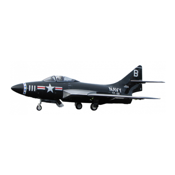
Grumman F-9F Cougar
1/5.8 Scale
Length: 84", Wing Span: 72"
Weight: 26-27lbs Dry
Fuel Capacity: 3.0L,
Smoke Capacity: 2.0L
CONSTRUCTION AND OPERATING MANUAL
Version 1.3
January 2017
Vne 165 MPH
Limit Thrust to 25 lbs.
Equipped with HV Servos and should not be operated below 7.2 volts
3481 State Road 419 • Winter Springs, FL 32708 USA
tel. 407-327-6333 • fax. 407-327-5020
K7000
BVM-2015
Advertisement
Table of Contents

Related Manuals for BVM Grumman F-9F Cougar


Summary of Contents for BVM Grumman F-9F Cougar
- Page 1 Grumman F-9F Cougar 1/5.8 Scale Length: 84”, Wing Span: 72” Weight: 26-27lbs Dry Fuel Capacity: 3.0L, Smoke Capacity: 2.0L CONSTRUCTION AND OPERATING MANUAL Version 1.3 January 2017 Vne 165 MPH Limit Thrust to 25 lbs. Equipped with HV Servos and should not be operated below 7.2 volts 3481 State Road 419 •...
-
Page 2: Table Of Contents
Installing the Engine ....................... 12 Front Fuselage Section ...................... 16 General Preparation ....................... 16 Mount the BVM UAT ....................... 16 Mount the Fuel Pump ..................... 16 Mount the ECU ....................... 17 Mount the Receiver ......................17 ... - Page 3 Flight Time ........................41 Taxi Test/Engine Run Up ....................41 Takeoff ........................... 41 Trim ..........................41 Practice Approaches ...................... 41 Landing ........................... 41 RX Battery Consumption ....................41 BVM ®2015 Printed 7/3/2019...
-
Page 4: Introduction
INTRODUCTION Thank you for purchasing the BVM F-9F Cougar. This model represents the latest in manufacturing technology and completion for the R/C jet enthusiast. The factory has expertly crafted and thoroughly inspected all aspects of the model. Only a small amount of work is required to complete the assembly of your Cougar. -
Page 5: Required Tools
Required Tools Metric Allen wrench set Needle nose Pliers BVM Clevis Tool BVM# PA-SR-0060 9/64 Ball Driver Perma Grit Large Flat File BVM# LNF-FLAT 6” long 1/16 drill List of Adhesives/Lubricants Pacer Z-42 PT42 Super O-Lube BVM #5779 Axle Super Lube BVM #5784 Available Options #V-WB 10"... -
Page 6: Unpacking
Support the fuselage on a stand. Be sure to use foam padding to prevent scratching and denting. Fill air system to around 50 Psi, use a piece of scrap air line pressed into the BVM Fill Valve (typical). -
Page 7: Tail Section
The servo cover screw heads can be hidden with paint as well. NOTE: The color paint on your BVM Cougar is blended to match U.S. Federal Standard (F.S.) Numbers. These F.S. number paints are available from Testor’s “Model Master” plastic model paints. -
Page 8: Installing The Horizontal Stabilizer
NOTE: Secure the elevator servo connection with a plastic clip or tape. Apply a drop of Pacer Z-42 to the (4) stabilizer bolts and secure the stab to the fuselage with a 3mm Allen wrench. BVM ®2015 Printed 7/3/2019... - Page 9 See Control “Travels” at end of this manual. Reconnect the (2) elevator ball links. Apply a drop of Z-42 on the end of the bolt that protrudes beyond the nut. BVM ®2015 Printed 7/3/2019...
-
Page 10: Installing The Vertical Fin
Use 320 grit sand paper to stroke the rods in the long direction. The grain should be the same as the direction of insertion. Apply a small amount of Lube to three tubes. BVM ®2015 Printed 7/3/2019... - Page 11 Do not continue to loosen the bolt once you feel the resistance of the “E” clip, you will damage and loose the “E” clip. Install the rear rudder post bolt through the lower rudder using a 2mm Allen wrench. BVM ®2015 Printed 7/3/2019...
-
Page 12: Mid Fuselage Section
Prepare the engine and engine mount. The standard P-100RX mount supplied with the engine is used in this prototype. Use the #6 Truss Head screws provided from BVM to secure the engine. Set the engine and mount in place, get familiar with the next few steps before proceeding. - Page 13 Remove the smoke tube. Remove the tail pipe screws and slide the tailpipe aft to allow access to the engine mounting rail bolts. Remove the engine mounting rail bolts with a 2mm Allen wrench. BVM ®2015 Printed 7/3/2019...
- Page 14 (4) mounting holes. JetCat P-100RX distance from bellmouth = 7/8” KingTech K-100G distance = 7/8”-1” Use a 6” long 1/16” drill to make the (4) holes for the #6 Truss Head wood screws. BVM ®2015 Printed 7/3/2019...
- Page 15 Relocating the Smoke Tube. Route the engine fuel and electrical lines. Use small zip ties to maintain security and an organized installation. Not shown here, but use a F.O.D. screen. BVM ®2015 Printed 7/3/2019...
-
Page 16: Front Fuselage Section
Mount the BVM UAT Two 11” zip ties are used to secure the BVM UAT between its mounts. Mount the Fuel Pump Secure the fuel pump using an 8” zip tie. (King Tech fuel pump shown) BVM ®2015... -
Page 17: Mount The Ecu
Mount the ECU Secure the ECU in place with wide “Sticky” Velcro; supplied with the BVM Manual packages. If your ECU allows for screws, they could be used as well. Mount the Receiver Secure the receiver in place with wide “Sticky”... -
Page 18: X+8 Xpander And Optional Gyro
Expansion Module. Refer to your gyro manufacturer’s recommendations for mounting your (optional) gyro. BVM adds a Velcro strap for security. The Cortex gyro is shown. The gain values used are 40% for normal flight and 60% for landing. -
Page 19: Switch
Reinstall the (2) Phillips head screws to secure the tray. Switch Mount the Receiver’s switch in the location provided. BVM ®2015 Printed 7/3/2019... - Page 20 Mount Remote Receivers in various positions, follow the recommendations for your particular receiver. Use Aluminum Tape to secure the wires. BVM ®2015 Printed 7/3/2019...
-
Page 21: Final Install Photos
Final install Photos Mount the fuel filter vertical; a BVM Fuel Pump Mount BVM# PA-SR-0064 was used. A piece of aluminum tape (arrow) secures the vent hose to the side of the fuel tank. BVM ®2015 Printed 7/3/2019... -
Page 22: Nose Cone Section
Front Battery Tray Remove the (4) bolts and washers from the nose of the aircraft. Assemble the ply wood nose formers to the fuselage as shown. Reinstall the bolts and washers. BVM ®2015 Printed 7/3/2019... -
Page 23: Miscellaneous Equipment
I/O board, Mini GSU, or Mini HDT. The KingTech Data connection is brought to the front using a 9” extension. The receiver’s bind connection is brought to the front using a 12” extension. BVM ®2015 Printed 7/3/2019... -
Page 24: Battery Extensions
Fuel system “fill line” is routed from the BVM UAT as shown. Trim end occasionally to keep aluminum plug fitting tight. A suction leak would cause a flame out. Battery Extensions Because a larger ECU battery was used for ballast and capacity reasons. -
Page 25: Nose Cone
Adjust the length of the four bolts to a suitable amount of friction. BVM factory demo Cougars have never had a problem with this method of attaching the nose cone. It is very convenient. -
Page 26: Cockpit/Pilot
Remove the pilot’s legs at the knees. It is not necessary to cut his pants. www.shopbvmjets.com/Pilots for pilot options. 10" Jet Pilot shown BVM # V-WB-10" Jet Pilot BVM ®2015 Printed 7/3/2019... - Page 27 BVM ®2015 Printed 7/3/2019...
-
Page 28: Wing Section
Avoid getting paint on the clevis. The servo cover screw heads can be hidden with paint as well. Secure Flap Hinge Bolts Use Pacer Z-42 to secure the flap hinge bolts. A drop on the extended threads is sufficient. BVM ®2015 Printed 7/3/2019... -
Page 29: Installing Wings
Important! The clamping bolts have “E” clips on the ends of the bolts to prevent the bolt from falling out during transportation. Do not continue to loosen the bolt once you feel the resistance of the “E” clip, you will damage and loose the “E” clip. BVM ®2015 Printed 7/3/2019... -
Page 30: Lubing The Brakes
Inflate to 30-40 psi for good ground handling. Wheel Bearing Maintenance Apply Super Lube BVM# 5784 into the wheel bushings. Reinstall the axel, wheel, and brake. BVM ®2015... -
Page 31: Systems Information
Spektrum SPM12120 Power Safe receiver. The speed of the pump is variable based on the travel adjustment on the radio. BVM uses a simple on/off switch to turn smoke on and off. The “on” travel adjustment is reduced to 65%. This allows a sufficient smoke trail without wasting smoke fluid. -
Page 32: Air System And Electronics (For Models Shipped Prior To September 2015)
Brakes” for instructions. Fill the Air system to 70 psi, or 4.8 bar before each flight. Helpful Tip: Use a scrap piece of BVM Air Line inserted into the fill valve; chamfer the end for easy insertion. PSI to BAR Conversion Table BVM ®2015... -
Page 33: Landing Gear/Door /Brake Sequencer Instructions
Increasing 1 second for each press, maximum 16 seconds, program will restart when over 16 seconds. The value sets only the time between “gear retraction and door closing” and “gear extension and door closing”. The Cougar works well using a value of “2”. BVM ®2015 Printed 7/3/2019... -
Page 34: Light System
Note: “Thro” input is not used. There should be one set of open pins on the output side of the light controller, these are unused. The light channel coming from the RX has three positions, Off, NAV Only, and NAV and Landing lights. BVM ®2015 Printed 7/3/2019... -
Page 35: Central Control Unit Instructions
Loss Protection Setup”. This feature will deploy the landing gear in the event of a leak. Increase the feature by 10PSI with each press, max. is 60PSI. Hold the “SETUP” button down and the setting will be saved. Press the “SETUP” button and “V” will be displayed. BVM ®2015 Printed 7/3/2019... - Page 36 “Manual” button or transmitter switch will become deactivated and will not work. The pressure will have to be raised to a pressure higher than the previously set value (Refer to C-2). Resetting the value to “000” will eliminate the flashing. BVM ®2015 Printed 7/3/2019...
-
Page 37: Light Connections (New Style Controller-September 2015)
Note: The lights receive power through all leads from the RX to the Central Control Unit (Nose IN, Brake, Light, Gear) An optional battery can supply power through the “BATT” lead. NOTE: Verify the polarity of all connections before applying power. BVM ®2015 Printed 7/3/2019... -
Page 38: Flush Mount Vent And Overflow System
Use an overflow tank while fueling to prevent spillage and to ensure fuel tanks are full before flight. Use BVM Overflow tank Part #BVM6047 Below, the overflow/taxi tank is connected. Install the vent plug for transport. BVM ®2015 Printed 7/3/2019... -
Page 39: Center Of Gravity
1-1/2” 3” Measured at the outside corner Note: The BVM Demo plane is setup using the above Expo percentages. Positive values are used on Spektrum and JR radios, Futaba uses negative. The body flap measurement is made from the furthest aft point. -
Page 40: Connecting Rx Wires
Flap DX18 and DX18QQ Transmitter File The BVM Demo models are setup on Spektrum DX18 transmitters. The file included on the SD card has all the mixes, rates, expos, and settings done for you. Setting the sub trim and travel adjustment must be accomplished by the modeler for the specific aircraft. Each aircraft is tested at the factory using a similar program. -
Page 41: First Flight Profile
First Flight Profile Flight Time The BVM demo model’s transmitter timers are set for 7 min. On the first flight, land a few minutes early to check fuel consumption. Adjust the flight timer accordingly. Taxi Test/Engine Run Up A taxi test should include a radio range check with the engine running at various power levels. - Page 42 Pilot’s Notes: BVM ®2015 Printed 7/3/2019...
Need help?
Do you have a question about the Grumman F-9F Cougar and is the answer not in the manual?
Questions and answers