Table of Contents
Advertisement
Quick Links
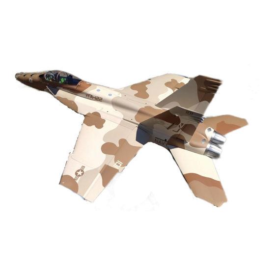
BVM PNP F/A-18F Super Hornet
ASSEMBLY AND OPERATING MANUAL
1/7.75 Scale
Length: 88", Wing Span: 67", Weight: 24# Dry, Fuel Capacity: 3.2L, Smoke: 2.2L
CONSTRUCTION AND OPERATING MANUAL
Version 1.0
July 2017
Vne 170 MPH
Limit Thrust to 36 lbs.
Equipped with HV Servos and should not be operated below 7.2 volts
3481 State Road 419 • Winter Springs, FL 32708 USA
tel. 407-327-6333 • fax. 407-327-5020
IK3300
BVM‐2017
Advertisement
Table of Contents

Related Manuals for BVM Super Hornet PNP F/A-18


Summary of Contents for BVM Super Hornet PNP F/A-18
- Page 1 BVM PNP F/A-18F Super Hornet ASSEMBLY AND OPERATING MANUAL 1/7.75 Scale Length: 88”, Wing Span: 67”, Weight: 24# Dry, Fuel Capacity: 3.2L, Smoke: 2.2L CONSTRUCTION AND OPERATING MANUAL Version 1.0 July 2017 Vne 170 MPH Limit Thrust to 36 lbs.
-
Page 2: Table Of Contents
Turbine Mounting and Ultimate Air Trap ...................... 8 Battery Mounting.............................. 9 Wheels & Brakes Preparation .......................... 10 Connecting RX wires ............................ 10 Gyro .................................. 11 Control Deflections ............................. 11 Center Of Gravity .............................. 12 First Flight Profile .............................. 13 Taxi Test/Engine Run Up ........................ 14 Takeoff ................................ 14 RX Battery Consumption ........................... 14 BVM ®2017 1 08/04/2017 ... -
Page 3: Introduction
Do not use with incompatible components or alter this product in any way outside of the instructions provided by BVM, Inc. The BVM F-18 has been designed and flight tested around 36 lbs class engines. Damage to the aircraft may result from exceeding this thrust limitation (36 lbs). -
Page 4: Recommended Accessories
(# VU-7304EXB-EC3) Fuel Pump/Filter Mount (# PA-SR-0064) Demon Aero Cortex Gyro Pro (# V-DA-BD-CortexPro) Cortex USB PC Adapter (# V-DA-BD-PC Adapter) BVM Over Flow Tank (BVM # 6047) 8" Warbird Jet Pilot (#V-WB 10"/8 JET PILOT) Fill line BVM Ultimate Air Trap BVM ®2017 3 ... -
Page 5: Required Tools
(# PA-SR-0042) Slo-Zap (# PT20) Pacer Z-42 (#PT42) Super O-Lube (BVM #5779) BVM Thin Lube for “O” Rings (BVM # 1945) Axle Super Lube (BVM # 5784) BVM Dry Lube (BVM # 1947) Accessories Used to Complete Prototype 1 x AR20310T 20-Channel PowerSafe Integrated Telemetry Receiver (SPMAR20310T) 2 x 12-inch EC3 Extension with 16AWG (SPMEXEC312) 2 x 3000-4000mAh 2S 7.4V LiPo Receiver Battery... -
Page 6: Installing The Horizontal Stabilizers
Begin assembly by removing and inspecting all airframe components. Carefully become familiar with the wiring, landing gear, gear doors, etc. The BVM F-18 PNP is not meant to be a primary turbine trainer. The manual assumes you already have experience with high performance turbine aircraft. -
Page 7: Wing Missile Rails
Install the left and right missile rails to the wing tips. Use a 3/32 driver to secure the clamp on the front dowel. Pro Tip: Use BVM Dry Lube (#1947) to allow dowel pins, tubes, and spars to be inserted with less friction. -
Page 8: Receiver And Gyro Installation
Cortex Pro gyro. This photo shows the same receiver, but using an iGyro 3e. A JR MatchBox was used to trim the dual rudders. This is necessary because the iGyro only features 5 outputs. BVM ®2017 7 08/04/2017 ... -
Page 9: Turbine Mounting And Ultimate Air Trap
Heatsheild was used on the inside of Turbine Hatch as added protection. (BVM#PA-MA-1940) Ultimate Air Trap is held in place by a single zip tie. Fuel Pump shown on left side of Ultimate Air Trap and Smoke Pump on right. -
Page 10: Battery Mounting
Use (2) 12” battery extensions to connect the RX to the Lipo batteries. Velcro strap and two pieces of sticky back Velcro can be used to secure long wires near the nose gear. BVM ®2017 9 08/04/2017 ... -
Page 11: Wheels & Brakes Preparation
Wheels & Brakes Preparation Apply a thin coat of Super O'Lube (BVM#5779) to the O'Ring. This will make braking smoother. When you notice the brakes starting to become more aggressive repeat this step. NOTE: If you need to remove the O'Ring. Use a sharpened wood stick to help remove the O'Ring. -
Page 12: Connecting Rx Wires
Connecting RX wires The wires are labeled from the factory. If you are using the DX18, the program is available on a SD card from BVM. Follow the chart below to connect the servos. DX18 Wire Connection Chart RX Port... -
Page 13: Control Deflections
Down from Vertical Fin Junction at the Stab Leading Edge Flaps Takeoff 3-⅜” Gear Down Flaps Landing 3-⅝” Gear Down *These measurements are a good baseline. Note: Photos show stabilizer deflections and trim positions from table above. BVM ®2017 12 08/04/2017 ... -
Page 14: Center Of Gravity
To help mark the Center of Gravity position when the wing is in place, you can use two Buttonhead screws on the bottom of fuse at the fuse wing joint. (BVM # 5625) ... -
Page 15: First Flight Profile
First Flight Profile Flight Time The BVM demo model’s transmitter timers are set for 6 min. On the first flight, land a couple minutes early to check fuel consumption. Adjust the flight timer accordingly. Taxi Test/Engine Run Up A taxi test should include a radio range check with the engine running at various power levels. - Page 16 BVM is synonymous with “Success Jets.” It is very important to us that you are successful with our products. This extensive manual reflects our sincerity. As always, your comments and suggestions on BVM products are appreciated. Pilot’s Notes: BVM ®2017 ...
Need help?
Do you have a question about the Super Hornet PNP F/A-18 and is the answer not in the manual?
Questions and answers