Table of Contents
Advertisement
Quick Links
FEATURES
Integrated calibration operation
►
Data logger
►
UART to USB communication
►
Universal connector for DMM
►
DOCUMENTS NEEDED
ADMX3652
data sheet
►
SOFTWARE NEEDED
ADMX3652 Evaluation GUI Software
►
PLEASE SEE THE LAST PAGE FOR AN IMPORTANT
WARNING AND LEGAL TERMS AND CONDITIONS.
Evaluating the ADMX3652 6½ Digit, ±20 V Digital Voltage Meter
User Guide | EVAL-ADMX3652
GENERAL DESCRIPTION
The ADMX3652 is a 6½ digit, ±20 V, dual-channel digital voltage
module with a small form factor that can be easily integrated
into a system. The module provides three measurement ranges
that can be selected manually or automatically according to the
input voltage. All operations are implemented through universal
asynchronous receiver-transmitter (UART) communications with the
Standard Commands for Programmable Instruments (SCPI) proto-
col. When the ADMX3652 connects with Analog Devices, Inc.,
EVAL-ADMX3652-INT evaluation board, it can be used as a porta-
ble measuring instrument that has two voltage input channels using
banana jack connectors. The measured data is output to a comput-
er through the UART to USB function on the EVAL-ADMX3652-INT.
An intuitive graphical user interface (GUI) tool is provided as well
for operating the module and capturing the data in the computer to
evaluate the performance of the ADMX3652.
UG-2138
Rev. B | 1 of 22
Advertisement
Table of Contents

Subscribe to Our Youtube Channel
Related Manuals for Analog Devices ADMX3652


Summary of Contents for Analog Devices ADMX3652
-
Page 1: Features
Evaluating the ADMX3652 6½ Digit, ±20 V Digital Voltage Meter FEATURES GENERAL DESCRIPTION Integrated calibration operation The ADMX3652 is a 6½ digit, ±20 V, dual-channel digital voltage ► module with a small form factor that can be easily integrated Data logger ►... -
Page 2: Table Of Contents
Calibrate with the ADMX3652 Evaluation Quick Start Guide..........4 GUI Software..........18 Electrical Installation..........5 Calibrate with SCPI Commands.......20 Plug and Pull Installation........5 Calibration of the ADMX3652 with Third Soldering Installation.......... 5 Parties............21 Module Operation..........6 Technical Support..........22 ADMX3652 Evaluation GUI Software....6 REVISION HISTORY 7/2024—Rev. - Page 3 Changes to System Commands Section, Table 11 Title, Table 12 Title, Table 13 Title, Table 14, and Table 15 Title..............................15 Added Table 16.............................. 16 Changes to Error Operating the ADMX3652 Evaluation GUI Software Section..........16 Changes to Table 17............................17 8/2023—Revision 0: Initial Version analog.com...
-
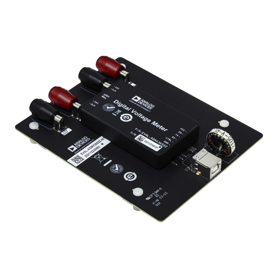
Page 4: Quick Start Guide
1. Mount the ADMX3652 firmly together with the EVAL- ADMX3652-INT interface board. Figure 2. ADMX3652 Installed on EVAL-ADMX3652-INT Interface Board Figure 4. ADMX3652 Evaluation GUI in Light Mode (Left) and Dark Mode (Right) analog.com Rev. B | 4 of 22... -
Page 5: Electrical Installation
ADMX3652 for regular calibration. SOLDERING INSTALLATION Alternatively, another available installation approach is to solder the ADMX3652 directly onto the system board of the user with reserved pads on the board for minimum stack-up height. analog.com Rev. B | 5 of 22... -
Page 6: Module Operation
Note that it requires a computer running Windows 10 or newer to run the ADMX3652 Evaluation GUI Software tool. For normal display, the resolution must be equal to or greater than 1024 × 768. -
Page 7: Change To Driver Installation Section
User Guide EVAL-ADMX3652 MODULE OPERATION package is then extracted and installed. After it completes the Driver Installation installation process, click Finish. After downloading the FTDI FT232RNL driver from the FTDI web- Only after the driver installation is complete can the... - Page 8 User Guide EVAL-ADMX3652 MODULE OPERATION Then, navigate to the directory that you want to install the ADMX3652 Evaluation GUI Software ADMX3652 Evaluation GUI Software to and click Next. After Installation installation completes, click Finish (see Figure Double-click on the ADMX3652 Evaluation GUI Software...
-
Page 9: Changes To Software Operation Section, Figure 10, And Figure 11
The baud rate must match device's setting and the factory default setting of baud rate is 460, 800. Then, click Confirm to continue. Figure 10. Serial Port Configuration Figure 11. ADMX3652 Evaluation GUI in Display Modes analog.com Rev. B | 9 of 22... -
Page 10: Changes To Figure 12
Connect or Disconnect Function Light and Dark Mode Function After a connection to the ADMX3652 is established, the Connect button changes to Disconnect. Click Disconnect to disconnect the The user interface can be set according to the preference of the communication between the ADMX3652 Evaluation GUI Software user. -
Page 11: Changes To Data Logger Function Section And Figure 19
User Guide EVAL-ADMX3652 MODULE OPERATION The measurements of Channel 1 and Channel 2 are recorded and Data Logger Function saved separately. The Data Logger function records all measured data during the When it is connected, the Data Logger starts to record measure- process, which can be exported to an excel file. -
Page 12: Added Data Plotter Function Section, Figure 20, And Figure 21; Renumbered Sequentially
Y-axis scale on the left. In contrast, the meas- 10% tolerance. If the Auto option is selected, the ADMX3652 urement results of channel 2 are plotted in blue curve with Y-axis automatically switches the measurement range based on the input scale on the right. -
Page 13: Scpi Commands
SCPI protocol, refer to the SCPI Consortium or the IEEE Standard 488. ADMX3652 Self Test Once the ADMX3652 is powered up, it starts a self test, and outputs self test information through its communication port. The Figure 26. Set Baud Rate self test process checks power rails one by one. -
Page 14: Changes To Table 1
EVAL-ADMX3652 MODULE OPERATION 10 seconds on a hot start. After the self test process completes, the Table 5. Command, CONFigure:VOLTage:DC? ADMX3652 outputs a DAQ is ready to use message. Syntax CONFigure:VOLTage:DC? {1|2} Function Queries the measuring voltage range of Channel 1 or IEEE 488.2 Common Commands... -
Page 15: Changes To Trigger Command Section
This command is only valid when a channel is set to single of the UART communication. read mode. The ADMX3652 returns a measured voltage value after the aperture time of the channel. Table 10. Rule of Baud Rate and Minimum NPLC Setting... -
Page 16: Error Codes And Troubleshooting
SYSTem:CAL:DATE 2023, 01, 01. Communication Table 20. Command, SYSTem:CAL:DATE? Syntax SYSTem:CAL:DATE? When communicating with the ADMX3652, error codes or messag- es can be returned from the device. Refer to Table 24 for error code Function Queries the last calibration date. - Page 17 "ADC encounter ADC_ERROR...". **ERROR: -113, "Undefined header" This command is not supported by the ADMX3652. Change the command to a supported command and retry. **ERROR: -224, "Illegal parameter value" The parameter does not comply with the command. Check the parameter and retry.
-
Page 18: Calibration
Calibrate: 0.2V to complete the positive full-scale calibration for 2. Power on and warm up the ADMX3652 for at least 30 minutes, the 0.2 V range. and then connect the Channel 1 (CH1) port to the calibrator via 7. - Page 19 User Guide EVAL-ADMX3652 CALIBRATION Note that typically, calibration adjustment involves the use of pre- cise devices of electrical signal sources that evaluate the perform- ance of key properties for other devices called units under test (UUT). Because these precise devices have thoroughly known...
-
Page 20: Calibrate With Scpi Commands
7. Follow Step 3 to Step 6 to complete the calibration for 2 V and 20 V range. 2. Power on and warm-up the ADMX3652 for at least 30 minutes, and then connect the Channel 1 port to the calibrator via the 8. -
Page 21: Parties
User Guide EVAL-ADMX3652 CALIBRATION CALIBRATION OF THE ADMX3652 WITH THIRD PARTIES As a general-purpose digital multimeter, the ADMX3652 can be calibrated by third-party metrology institutes. Contact Analog Devi- ces sales for additional information on calibration service. analog.com Rev. B | 21 of 22... -
Page 22: Technical Support
Evaluation Board until you have read and agreed to the Agreement. Your use of the Evaluation Board shall signify your acceptance of the Agreement. This Agreement is made by and between you (“Customer”) and Analog Devices, Inc. (“ADI”), with its principal place of business at Subject to the terms and conditions of the Agreement, ADI hereby grants to Customer a free, limited, personal, temporary, non-exclusive, non-sublicensable, non-transferable license to use the Evaluation Board FOR EVALUATION PURPOSES ONLY.
Need help?
Do you have a question about the ADMX3652 and is the answer not in the manual?
Questions and answers