Table of Contents
Advertisement
Quick Links
One Technology Way • P.O. Box 9106 • Norwood, MA 02062-9106, U.S.A. • Tel: 781.329.4700 • Fax: 781.461.3113 •
FEATURES
Debug and programming capability for
Evaluation capabilities for bioelectric and electrochemical
measurements
SensorPal GUI user guide for electrochemical and bioelectric
measurements
EVALUATION KIT CONTENTS
EVAL-AD5940BIOZ evaluation kit
EVAL-ADICUP3029
EVAL-AD5940ARDZ
AD5940-BioElectric
ECG snap connector to micro USB cable
Micro USB to USB cable
EVAL-AD5940ELCZ evaluation kit
EVAL-ADICUP3029
EVAL-AD5940ARDZ
AD5940Sens2
MicroUSB to USB cable
GENERAL DESCRIPTION
This user guide refers to the
included allow the evaluation of the
LIMITATIONS ON USE AND LIABILITY
The application described in this application note is specific to the
ADICUP3029
evaluation board. In addition to the terms of use contained in the evaluation board user guides, it is understood and agreed
to that the evaluation board or design must not be used for diagnostic purposes and must not be connected to a human being or animal.
This evaluation board is provided for evaluation and development purposes only. It is not intended for use or as part of an end product.
Any use of the evaluation board or design in such applications is at your own risk and you shall fully indemnify Analog Devices, Inc., its
subsidiaries, employees, directors, officers, servants and agents for all liability and expenses arising from such unauthorized usage. You are
solely responsible for compliance with all legal and regulatory requirements connected to such use.
EVAL-AD5940 Evaluation Kit User Guide
AD5940
Evaluation Kit User Guide
AD5940
AD5940
evaluation kit. The boards
AD5940
and all its features.
www.analog.com
The
ADICUP3029
containing the
firmware and communicates with the AD5940.
The EVAL-AD5940ARDZ board is designed to be versatile and
enable different measurements, such as bioelectric, electrochemical,
and potentiostat measurements. This is made possible by the
expander board headers. The
boards. The
AD5940-BioElectric
biopotential measurements, and the
amperometric and impedance measurements.
The evaluation kit also includes custom USB to ECG cables to
connect the kit to the human body for bioelectric and biopotential
measurements.
AD5940
and the
AD8233
Rev. 0 | Page 1 of 27
board is an Arduino form factor motherboard
ADuCM3029
microcontroller that runs sample
AD5940
kit contains two expander
for bioimpedance and
AD5940Sens2
for use with the
EVAL-
UG-1292
for
Advertisement
Table of Contents

Related Manuals for Analog Devices ADICUP3029


Summary of Contents for Analog Devices ADICUP3029
-
Page 1: Features
This evaluation board is provided for evaluation and development purposes only. It is not intended for use or as part of an end product. Any use of the evaluation board or design in such applications is at your own risk and you shall fully indemnify Analog Devices, Inc., its subsidiaries, employees, directors, officers, servants and agents for all liability and expenses arising from such unauthorized usage. -
Page 2: Table Of Contents
Measurement Validation and Testing .........8 Revision History ................2 Tips and Tricks ................23 Evaluation Hardware ................ 3 Troubleshooting................24 EVAL-ADICUP3029 ..............4 Installing and Using IAR Workbench .......... 25 EVAL-AD5940ARDZ ..............4 How to Download IAR .............. 25 AD5940-BioElectric ..............5 Running Example Firmware in IAR ........ -
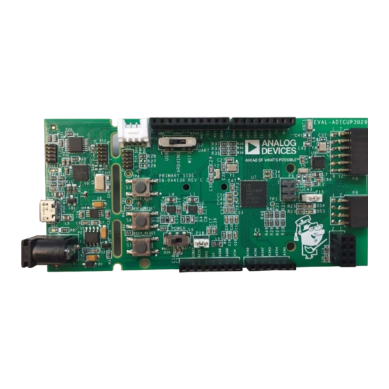
Page 3: Evaluation Hardware
EVAL-AD5940 Evaluation Kit User Guide UG-1292 EVALUATION HARDWARE Figure 4. AD5940Sens2 Daughter Card Figure 1. EVAL-ADICUP3029 Figure 5. AD5940 Impedence Test Board Figure 2. EVAL-AD5940ARDZ Figure 6. USB to Micro-USB Cable Figure 3. AD5940-BioElectric Evaluation Daughter Card Figure 7. Custom ECG Cables... -
Page 4: Eval-Adicup3029
Switch 5. Board Setup Figure 10. Device Manager Unpack the board and ensure S2 is switched to USB position. For further information about the EVAL-ADICUP3029, visit Ensure S5 is switched to wall/USB (see Figure 8). EVAL-ADICUP3029 product page. -
Page 5: Ad5940-Bioelectric
EVAL-AD5940 Evaluation Kit User Guide UG-1292 • Add R18 and R19. Calculate R18 and R19 using the following equation: Table 1. Default Jumper Descriptions = 1.0 V (1 + R18/R19) + R18 Jumper Description JP4, JP5 Enable the low dropouts (LDOs); By For further clarity, refer to EVAL-AD5940ARDZ.pdf, located in default, the LDOs are disabled the AD5940Firmware&Documentation folder. -
Page 6: Sensorpal User Guide
An Analog Devices folder is automatically created in the C to the right of the dropdown to refresh the list of ports (see drive on your PC. -
Page 7: Quick Test
Open the SensorPal GUI and ensure the correct COM port following steps: is connected. Plug the AD5940ARDZ into the ADICUP3029 via the Under the Bio-Electric Techniques section in the tool belt, Arduino connectors. drag the Body Impedance measurement into the work Plug the... -
Page 8: Measurement Validation And Testing
To perform a body impedance validation test using AD5940 evaluation board, take the following steps: Plug the AD5940ARDZ into the ADICUP3029 via the Arduino connectors. Plug the ADICUP3029 into the PC via the microUSB port on the board. - Page 9 EVAL-AD5940 Evaluation Kit User Guide UG-1292 Click the Body Impedance measurement to highlight it 11. The results are the absolute impedance value and and view the configurable parameters beneath. The body force/sense out the isolation components in the paths on impedance parameters that can be set are shown in Table 2 F+ and F−...
- Page 10 UG-1292 EVAL-AD5940 Evaluation Kit User Guide Figure 21. Bioelectric Board Electrode Schematic 12. When the software has finished collecting data, the resulting Electrodermal Activity graph looks similar to the one in Figure 22 (sampled at one Electrodermal activity (EDA) refers to the continuous changes frequency).
- Page 11 EVAL-AD5940 Evaluation Kit User Guide UG-1292 Plug the AD5940ARDZ into the ADICUP3029 via the Select the desired resistor value on the impedance test Arduino connectors. board using the switches on the S2 and S3 banks. Plug the AD5940-BioElectric evaluation daughter card into...
- Page 12 UG-1292 EVAL-AD5940 Evaluation Kit User Guide Figure 26. EDA Measurement Block Diagram Figure 27. Bioelectric Electrodes Schematic • CE0 to F+ = R = R82 = 1 kΩ and C = C68 = After the desired parameters are set, press the green LIMIT 0.015 µF Measure button to begin collecting data.
- Page 13 EVAL-AD5940 Evaluation Kit User Guide UG-1292 Figure 28. EDA Validation Test Result—4.22 MΩ on Impedance Test Board measure ECG rate on a sensor/ECG simulator. The ECG cables are labeled in Figure 30. If using electrodes to measure EDA on an equivalent sensor, the leads on the custom ECG cable provided are as in Figure 29.
- Page 14 Blue (S−) to RA (right arm) following the instructions below: • Green (S+) to LL (left leg) Plug the AD5940ARDZ into the ADICUP3029 via the • Black (F−) to RLD (right leg drive) Arduino connectors. Plug the AD5940-BioElectric evaluation daughter card into...
- Page 15 EVAL-AD5940 Evaluation Kit User Guide UG-1292 Click the Electrocardiogram measurement to highlight it For more information on ECG measurements on the AD5940, refer to and view the configurable parameters beneath. The ECG the AN-1557. parameters that can be set are shown in Table 5. 10.
- Page 16 To perform a linear sweep voltammetry validation test using AD5940 evaluation board, follow the instructions below: Plug the AD5940 evaluation board (EVAL-AD5940ARDZ) into the Arduino connectors on the ADICUP3029. Plug the AD5940Sens2 daughter card into Figure 35. JP6 Jumper Configuration for Voltammetry Test on Sens2 Board Connect the...
- Page 17 EVAL-AD5940 Evaluation Kit User Guide UG-1292 continue collecting data until all of the samples have been Figure 36, the response current (green) increases as the taken. input voltage (blue) increases with time, which is expected. When you have finished collecting data, the resulting graph should look similar to the one in Figure 36.
- Page 18 RC circuit. The board Plug the AD5940 evaluation board (AD5940ARDZ) into applies a step voltage to the circuit and measures the response the Arduino connectors on the ADICUP3029 current, which ideally is a decaying exponential. Plug the AD5940Sens2 daughter card into the AD5940ARDZ board as in Figure 37.
- Page 19 EVAL-AD5940 Evaluation Kit User Guide UG-1292 Click the Amperometry measurement to highlight it and view the configurable parameters beneath. Ensure the parameters are set to the values shown in Figure 39. Board Configuration for Two Amperometric Measurement Tests Table 6. Table 6.
- Page 20 UG-1292 EVAL-AD5940 Evaluation Kit User Guide Figure 40. Amperometry Validation Test—TEST 1 Results Rev. 0 | Page 20 of 27...
- Page 21 Delete any other existing measurements in the work area Plug the AD5940 evaluation board (AD5940ARDZ) into by hovering over the measurement and pressing the trash the Arduino connectors on the ADICUP3029. bin icon in the bottom right corner. Plug the AD5940Sens2 daughter card into...
- Page 22 UG-1292 EVAL-AD5940 Evaluation Kit User Guide After the parameters are set, press the green Measure When all data is collected, the resulting graph looks similar button to begin collecting data. The measurement should to the one in Figure 42. As expected, the impedance of the stop once all of the samples have been acquired.
-
Page 23: Tips And Tricks
EVAL-AD5940 Evaluation Kit User Guide UG-1292 TIPS AND TRICKS Hover over a point on the graph to view the point’s x-value. Enable help mode to get information about specific parameters, measurement techniques, and measurement Click on the point to view the point’s y-value. theories. -
Page 24: Troubleshooting
UG-1292 EVAL-AD5940 Evaluation Kit User Guide TROUBLESHOOTING AD5940-BioElectric Daughter Card Ensure the jumpers on the AD5940-BioElectric daughter card If a user experiences errors with any of the validation tests or are in their default positions as described in Table 9. the resulting graphs do not look similar to the ones displayed in the previous sections, refer to the troubleshooting help below to Table 9. -
Page 25: Installing And Using Iar Workbench
EVAL-AD5940 Evaluation Kit User Guide UG-1292 INSTALLING AND USING IAR WORKBENCH IAR Workbench is the IDE of choice for developing firmware for theAD5940. IAR provides an evaluation licence that is free but limits the code size to 32 kB. Currently, none of the evaluation examples in the AD5940 development pack exceed this. -
Page 26: Running Example Firmware In Iar
PC via the UART interface. To view results open a terminal program such as RealTerm. Set the baud rate to 230400 and set the COM port to the port that ADICUP3029 is connected (see Figure 54). If unsure which port the ADICUP3029 connected to, go to device manager >... - Page 27 Evaluation Board until you have read and agreed to the Agreement. Your use of the Evaluation Board shall signify your acceptance of the Agreement. This Agreement is made by and between you (“Customer”) and Analog Devices, Inc. (“ADI”), with its principal place of business at One Technology Way, Norwood, MA 02062, USA. Subject to the terms and conditions of the Agreement, ADI hereby grants to Customer a free, limited, personal, temporary, non-exclusive, non-sublicensable, non-transferable license to use the Evaluation Board FOR EVALUATION PURPOSES ONLY.
Need help?
Do you have a question about the ADICUP3029 and is the answer not in the manual?
Questions and answers