Table of Contents
Advertisement
Quick Links
EVAL-ADMV8052
User Guide
UG-1951
One Technology Way • P.O. Box 9106 • Norwood, MA 02062-9106, U.S.A. • Tel: 781.329.4700 • Fax: 781.461.3113 • www.analog.com
Evaluating the
ADMV8052
30 MHz to 520 MHz, Digitally Tunable Band-Pass Filter
FEATURES
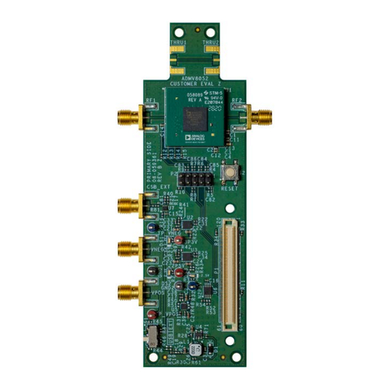
EVALUATION BOARD PHOTOGRAPH
Fully featured evaluation board for the ADMV8052
On-board
SDP-S
connector for the SPI
Evaluation using on-board LDO regulators powered by the USB
ACE
software interface for SPI control
EQUIPMENT NEEDED
Network analyzer
Windows® PC
USB cable
EVAL-SDP-CS1Z (SDP-S) controller board
DOCUMENTS NEEDED
ADMV8052 data sheet
SOFTWARE NEEDED
ACE software
GENERAL DESCRIPTION
The ADMV8052-EVALZ is available for evaluating the
ADMV8052 digitally tunable, band-pass filter (BPF). The
ADMV8052-EVALZ incorporates the ADMV8052 chip, as
well as a negative voltage generator, low dropout (LDO)
regulators, and an interface to the EVAL-SDP-CS1Z (SDP-S)
system demonstration platform (SDP) to allow simple and
efficient evaluation. The negative voltage generator and LDO
regulators allow the ADMV8052 to be powered by either the
5 V USB supply voltage from the PC via the SDP-S or by using
Figure 1.
two external power supplies.
The ADMV8052 is an IC that features a digitally selectable
frequency of operation. The chip features three BPFs that span
from 30 MHz to 520 MHz. The chip can be programmed using a
4-wire serial port interface (SPI), and the SDP-S controller allows
the user to interface with the SPI of the ADMV8052 through
the Analog Devices, Inc., Analysis | Control | Evaluation (ACE)
software.
For full details on the ADMV8052, see the ADMV8052 data
sheet, which must be consulted in conjunction with this user
guide when using the ADMV8052-EVALZ.
PLEASE SEE THE LAST PAGE FOR AN IMPORTANT
Rev. 0 | Page 1 of 18
WARNING AND LEGAL TERMS AND CONDITIONS.
Advertisement
Table of Contents

Related Manuals for Analog Devices EVAL-ADMV8052


Summary of Contents for Analog Devices EVAL-ADMV8052
-
Page 1: Features
4-wire serial port interface (SPI), and the SDP-S controller allows the user to interface with the SPI of the ADMV8052 through the Analog Devices, Inc., Analysis | Control | Evaluation (ACE) software. For full details on the ADMV8052, see the ADMV8052 data sheet, which must be consulted in conjunction with this user guide when using the ADMV8052-EVALZ. -
Page 2: Table Of Contents
UG-1951 EVAL-ADMV8052 User Guide TABLE OF CONTENTS Features ....................1 ADMV8052-EVALZ Quick Start ..........10 Equipment Needed ................1 Network Analyzer Settings ............10 Documents Needed ................1 CSV Files ..................10 Software Needed ................1 Automatic Chip Reset ..............11 General Description ................. -
Page 3: Evaluation Board Hardware
EVAL-ADMV8052 User Guide UG-1951 EVALUATION BOARD HARDWARE The ADMV8052-EVALZ has the ADMV8052 chip on board. Figure 2 shows an example lab bench setup for the ADMV8052- The ADMV8052-EVALZ also includes a negative voltage EVALZ. To observe the filter response from the ADMV8052-... -
Page 4: Evaluation Board Software
Attached Hardware section of the Start tab PLUG-INS, AND DRIVERS when the ACE software is running. (see Figure 4). The ADMV8052-EVALZ uses the Analog Devices ACE software. For instructions on how to install and use the ACE software, go to the software page. -
Page 5: Plug-In Overview
EVAL-ADMV8052 User Guide UG-1951 PLUG-IN OVERVIEW When the ADMV8052-EVALZ is connected to the PC, the ADMV8052 Board appears in the Attached Hardware section of the Start tab. Double-click the ADMV8052 Board plug-in to open two tabs, which are the ADMV8052 Board plug-in view (see Figure 5) and the ADMV8052 chip plug-in view (see Figure 6), respectively. -
Page 6: Plug-In Details
UG-1951 EVAL-ADMV8052 User Guide PLUG-IN DETAILS The full screen ADMV8052 chip plug-in with labels is shown in Figure 7. The labels correspond to items listed in Table 1, which describes the functionality of each section. For additional detailed programming, refer to the ADMV8052 data sheet. - Page 7 EVAL-ADMV8052 User Guide UG-1951 Label Function Band 1 Coefficients: define the interpolation coefficients for Band 1. Band 2 Coefficients: define the interpolation coefficients for Band 2. Band 3 Coefficients: define the interpolation coefficients for Band 3. Summary: click this button to review the settings for the initial setup.
- Page 8 UG-1951 EVAL-ADMV8052 User Guide Label Function The Display section determines the actively selected WR or LUT number. This section includes the following: Mode: use the drop-down menu to select either Write or LUT display mode. WR: when the Mode is set to Write, scroll up and down to set the WR number (0 to 3) that is currently being configured and displayed in the Filter Settings section.
- Page 9 EVAL-ADMV8052 User Guide UG-1951 Figure 8. ADMV8052 Memory Map in the Software Figure 9. Interpolation Values Subdiagram in the ACE Software Rev. 0 | Page 9 of 18...
-
Page 10: Performing Evaluation
UG-1951 EVAL-ADMV8052 User Guide PERFORMING EVALUATION ADMV8052-EVALZ QUICK START To set up the ADMV8052-EVALZ, take the following steps: Connect the RF1 and RF2 ports to a network analyzer (or a similar instrument). Typically, RF1 and RF2 are connected to Port 1 and Port 2 on the network analyzer, as shown in Figure 2. -
Page 11: Automatic Chip Reset
EVAL-ADMV8052 User Guide UG-1951 AUTOMATIC CHIP RESET LOSS OF BOARD COMMUNICATION If a reset of the ADMV8052 chip is required on the When the ADMV8052 is turned off and then on, or if the USB ADMV8052-EVALZ, click Reset Chip (see Figure 7 and cable is disconnected and connected while the ACE software is Label J3 in Table 1 for additional information). -
Page 12: Plug-In Spi Register Controller
UG-1951 EVAL-ADMV8052 User Guide PLUG-IN SPI REGISTER CONTROLLER Determine if the values have changed for any of the LUT registers (Register 0x100 to Register 0x2FF). The ADMV8052 plug-in utilizes an SPI register controller to If Step 6 is true, write to Register 0x100 to Register 0x2FF communicate with the ADMV8052. -
Page 13: Evaluation Board Schematics And Artwork
EVAL-ADMV8052 User Guide UG-1951 EVALUATION BOARD SCHEMATICS AND ARTWORK ADMV8052-EVALZ THRU2 THRU1 THRUCAL 50Ω TRACE LINE LENGTH SHALL BE SAME AS LAUNCHES TO/FROM RF1 AND RF2. 142-0701-851 142-0701-851 50Ω TRACE PAD1 PAD12 142-0701-851 PAD2 PAD11 N2P5V ADMV8052ACCZ 0.1µF 100pF 50Ω TRACE... - Page 14 UG-1951 EVAL-ADMV8052 User Guide Figure 12. ADMV8052-EVALZ Schematic, Page 2 Rev. 0 | Page 14 of 18...
- Page 15 EVAL-ADMV8052 User Guide UG-1951 Figure 14. ADMV8052-EVALZ Layer 2 Figure 13. ADMV8052-EVALZ Layer 1 Rev. 0 | Page 15 of 18...
- Page 16 UG-1951 EVAL-ADMV8052 User Guide Figure 16. ADMV8052-EVALZ Layer 4 Figure 15. ADMV8052-EVALZ Layer 3 Rev. 0 | Page 16 of 18...
-
Page 17: Ordering Information
EVAL-ADMV8052 User Guide UG-1951 ORDERING INFORMATION BILL OF MATERIALS Table 2. ADMV8052-EVALZ Qty. Reference Designator Description Manufacturer Part Number 2P5V, 3P3V, TP_VPOS Test points, red Components Corporation TP-104-01-02 GND1, GND2 Test points, black Components Corporation TP-104-01-00 N2P5V, TP_VNEG Test points, blue... - Page 18 By using the evaluation board discussed herein (together with any tools, components documentation or support materials, the “Evaluation Board”), you are agreeing to be bound by the terms and conditions set forth below (“Agreement”) unless you have purchased the Evaluation Board, in which case the Analog Devices Standard Terms and Conditions of Sale shall govern. Do not use the Evaluation Board until you have read and agreed to the Agreement.
Need help?
Do you have a question about the EVAL-ADMV8052 and is the answer not in the manual?
Questions and answers