Table of Contents
Advertisement
Quick Links
Advertisement
Chapters
Table of Contents

Related Manuals for Icom IC-M804


Summary of Contents for Icom IC-M804
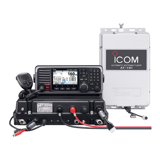
- Page 1 INSTRUCTION MANUAL MF/HF MARINE TRANSCEIVER |M804...
-
Page 2: Important
Thank you for choosing this Icom product. This IN CASE OF EMERGENCY product is designed and built with Icom’s state of the art technology and craftsmanship. With proper care, If your vessel requires assistance, contact other vessels this product should provide you with years of trouble- and the Coast Guard by sending a Distress call using Digital free operation. -
Page 3: Recommendation
You can use the following keys on the Menu screen. is cracked or broken, or the remote controller has been dropped. Contact your Icom distributor or your FUNCTION ACTION dealer for advice. -
Page 4: Precautions
−15°C or above radioactive contamination. +55°C, or in areas exposed to direct sunlight, such as • The use of Icom transceivers with any equipment the dashboard. that is not manufactured or approved by Icom. CAUTION: DO NOT use or leave the transceiver in Icom, Icom Inc. -
Page 5: Table Of Contents
TABLE OF CONTENTS D DSC Frequency ......47 IMPORTANT ........i Assigning a function ....... 18 D Assigning a Software Key D Scanning Receiver ....48 EXPLICIT DEFINITIONS ....i D Auto ACK ........49 function to a Software Key ..18 FEATURES ........i D Assigning a Software Key D CH Auto Switch ...... -
Page 6: Operating Rules
OPERATING RULES NOTE: Before transmitting, monitor the channel you want to use to avoid interrupting communications already in progress. z CALL PROCEDURE z RADIO LICENSES Calls must be properly identified and the time limit (1) SHIP RADIO STATION LICENSE must be respected. You need a current ship radio station license before using the transceiver. -
Page 7: Panel Description
PANEL DESCRIPTION ■ Main unit front panel 13 12 FERRITE EMI FILTER FERRITE EMI FILTER 10 11 1 GROUND TERMINAL [GND] (p. 64) 7 REMOTE CONNECTOR [REMOTE] (pp. 63, 72) Connect a PC through a USB to RS-422A Connects to the vessel’s ground. (D-sub 9 pin) cable for remote control. -
Page 8: Remote Controller Front Panel
PANEL DESCRIPTION ■ Remote Controller front panel 2 3 4 2 3 SPEAKER FUNCTION DISPLAY (p. 6) MICROPHONE SOFTWARE KEYS (p. 4) CONNECTOR (pp. 63, 71) 1 DISTRESS KEY [DISTRESS] 8 VOLUME DIAL [VOL] Hold down for 3 seconds to transmit a Distress call. z Rotate to adjust the speaker volume level. -
Page 9: Microphone
PANEL DESCRIPTION ■ Microphone ■ Software Keys Various often-used functions are assigned to the Software Keys for easy access. The function’s icons MICROPHONE are displayed above the Software Keys, as shown below. D Selecting a Software Key function Push [◄] or [►] to slide through the selectable functions that are assigned to the Software Keys. -
Page 10: D Functions
PANEL DESCRIPTION ■ Software Keys D Functions You can use various Software Key functions that are assigned to the Software Keys, as described below. Compose Distress RX Play Push to compose a Distress call. (pp. 25 ~ 29) Push to replay the recorded audio data. (p. 12) Compose Other TX FREQ Monitor Push to compose DSC calls other than Distress calls. -
Page 11: Function Display (Main Screen)
PANEL DESCRIPTION ■ Function display (Main screen) D Information area The 9 digit MMSI (Maritime Mobile Service Identity: Status area DSC self ID) code and the following indicators are Information area Task area displayed in the information area. Indicator Description Displayed when receiving a signal or when the squelch is open. -
Page 12: D Software Key Area
PANEL DESCRIPTION ■ Function display (Main screen) D Software Key area The Key function for each Software Key is displayed. See page 4 for details. D Position and Time area Position area The current position is displayed when valid GPS data is received, or when your position is manually entered. -
Page 13: Preparation
PREPARATION ■ Entering the MMSI code The Maritime Mobile Service Identity (MMSI: DSC self ID) code consists of 9 digits. You can only enter the code when turning ON the transceiver for the fi rst time. This initial code can be entered only once. After entering, it can be changed only by your dealer or distributor. -
Page 14: Basic Operation
BASIC OPERATION ■ Selecting a Channel or Group [ENT] D Using the channel and group selector 1. Push [CH/GRP] to toggle between the Channel Keypad Select mode and the Group Select mode. keys • is displayed. 2. Rotate [CH/GRP] to select a channel or group. L When selecting the Group Select mode, the User channels change in 20 channel steps. -
Page 15: Receiving And Transmitting
BASIC OPERATION ■ Receiving and transmitting [◄]/[►] D Receiving 1. Select a channel by rotating [CH/GRP] or pushing Keypad the Keypad keys. (p. 9) keys 2. When receiving a call, rotate [VOL] to adjust the audio output level. TIP: When a call is received: Software Keys [CH/GRP] [VOL]... -
Page 16: Fsk Operation
• The FSK mark frequency, shift frequency, and FSK terminal unit polarity can be selected in the FSK Settings. (p. 59) • Some transceivers may operate 1.7 kHz higher than the IC-M804’s J2B mode, even when the same displayed frequencies are in use. -
Page 17: Operations
OTHER FUNCTIONS AND OPERATIONS ■ Backlight function ■ Instant Replay function The function display and keys can be backlit for better The transceiver has an Instant Replay function that visibility under low light conditions. can record the last 120 seconds of the received audio. You can set the LCD backlight mode to Day mode You can playback the audio that you could not hear. -
Page 18: Scan
OTHER FUNCTIONS AND OPERATIONS ■ Scan The transceiver has automatic channel and frequency scan capabilities (Scan function). There are 3 types of scan functions. z CH (Channel) z CH Resume z Program D CH and CH Resume D Program The CH and CH Resume searches within a 20 The Program scan searches the selected channel within the frequency range set by the “Start frequency”... -
Page 19: Other Functions
OTHER FUNCTIONS AND OPERATIONS ■ Other functions Emergency FREQ channel Squelch function Select the Distress Voice Frequency. When this The Squelch function mutes unwanted signals such channel is selected, the Voice Frequency of a DSC as noise or unmodulated beat signals. This function call can be monitored without receiving or transmitting enables quiet standby. - Page 20 OTHER FUNCTIONS AND OPERATIONS ■ Other functions Transmit Frequency Monitor function When selecting a duplex channel, the transmit frequency diff ers from the receive frequency. To prevent interference to other stations, the transmit frequency should be monitored before you transmit. 1.
-
Page 21: Setting A Temporary Operating Frequency
OTHER FUNCTIONS AND OPERATIONS ■ Setting a temporary operating frequency You can temporarily change the operating frequency of the selected channel. The frequency returns to the preset value after you select another channel, or turn OFF the transceiver. 5. Enter a transmit frequency by using the Keypad 1. -
Page 22: Setting A User Channel Or An Itu Simplex Channel
OTHER FUNCTIONS AND OPERATIONS ■ Setting a User channel or an ITU Simplex channel Step 2. Setting an RX and TX operating frequencies Your dealer has already preset User channels and ITU Simplex channels. NOTE: The RX and TX operating frequencies are the Follow the instructions as described below only when same when an ITU Simplex channel is selected. -
Page 23: Assigning A Function
OTHER FUNCTIONS AND OPERATIONS ■ Assigning a function You can assign diff erent Software Key functions to a Step 4. Setting a channel name key between Softkey 1 and Softkey 20. (p. 18) You can set a channel name of up to 10 characters for each User channel or ITU Simplex channel. -
Page 24: D Assigning A Software Key Function To [Vol]
OTHER FUNCTIONS AND OPERATIONS ■ Assigning a function D Assigning a Software Key function to D Assigning a Software Key function to [VOL] [P] on the supplied microphone 1. Open “Volume Dial Assignment.” 1. Open “P Key Assignment.” [MENU] > Confi guration > Key Assignment > [MENU] >... -
Page 25: Dsc Operation
DSC OPERATION ■ About DSC Digital Selective Calling (DSC) is an automated digital NOTE: communication system defi ned by ITU-R M.493, and • To use a DSC call, entering the MMSI code is is also part of the Global Maritime Distress and Safety needed. -
Page 26: D Delete An Entered Id
DSC OPERATION ■ DSC address ID 14. Push to save the ID. • The entered name is displayed. 8. Select “Voice Frequency.” Rotate Push 9. Enter a receive frequency, and then push Finish Rotate Push 15. Push [MENU] to return to the Main screen. TIP: You can edit the settings of the selected ID by 10. -
Page 27: Entering The Position Data And Time
DSC OPERATION ■ Entering the position data and time A Distress call should include the vessel’s position, date, and time. If no GPS data is being received, manually enter the position and Universal Time Coordinated (UTC) time. NOTE: • Manual entry is disabled while valid GPS data is being received. -
Page 28: Dsc Task Mode
DSC OPERATION ■ DSC Task mode After sending or receiving a DSC call, the transceiver D Software Key functions enters the DSC Task mode. While in the DSC Task mode, the following functions The transceiver can hold only 1 task. are displayed fi rst. -
Page 29: Sending Dsc Calls (Distress)
DSC OPERATION ■ Sending DSC calls (Distress) A Distress call should be sent when, in the opinion of the captain, the vessel or a person is in distress and requires immediate assistance. NEVER MAKE A DISTRESS CALL IF YOUR VESSEL OR A PERSON IS NOT IN AN EMERGENCY. -
Page 30: D Regular Call
DSC OPERATION ■ Sending DSC calls (Distress) 2. Select an option. (Example: Multi Frequency) • The setting is saved and returns to the previous screen. D Regular call Rotate Select the nature of the Distress call to include in the Regular Distress call. -
Page 31: D Resending A Distress Call
DSC OPERATION D Resending a Distress call While waiting for an Acknowledgment, you can resend TIP: the call (Repeat call). Transmitting: 1. When the “Waiting for ACK” screen is displayed, • A default Distress alert contains: –Nature of distress: Undesignated distress push Resend –... -
Page 32: D Distress Cancel Call
DSC OPERATION ■ Sending DSC calls (Distress) D Distress Cancel call If you have accidentally made a Distress call, or made an incorrect Distress call, send a Distress Cancel call to cancel the call as soon as possible while waiting for an Acknowledgment. - Page 33 DSC OPERATION While waiting for Distress ACK 1. When “Waiting for Distress ACK” is displayed, 3. After sending, the following screen is displayed. push Push Cancel Select FREQ 4. Select a frequency to send a voice cancel message. L See page 23 for details of the Software Key Rotate functions in the DSC Task mode.
-
Page 34: Sending Dsc Calls (Other)
DSC OPERATION ■ Sending DSC calls (other) D Sending an Individual call An Individual call enables you to send a DSC signal to only a specifi c station. You can communicate normally after receiving the Acknowledgment “ACK (able).” L You can send an Individual call to a pre-entered Individual ID or manually enter the target station ID before sending. -
Page 35: D Sending An Individual Acknowledgment
DSC OPERATION D Sending an Individual Acknowledgment When you have received an Individual call (p. 41), send an Acknowledgment to the calling station. When “Manual” is selected in “Individual ACK” (p. 49), you can select an appropriate Acknowledgment type. 1. While an Individual call is being received, push to turn OFF the alarm. -
Page 36: D Sending A Group Call
DSC OPERATION ■ Sending DSC calls (other) D Sending an Individual Acknowledgment (Continued) D Sending a Group call 4. Confirm the contents. A Group call enables you to send a DSC call to only a specifi c group. L You can send a Group call to a pre-entered Group ID or Rotate manually enter the target group before sending. - Page 37 DSC OPERATION 6. Select “Call Frequency.” 10. Push to send a Group call. Call • “Transmitting Group Call” is displayed, and then Rotate “Group Call” is displayed. Push 7. Select a call frequency or “Manual Input.” L See page 23 for details of the Software Key Rotate functions in the DSC Task mode.
-
Page 38: D Sending A Geographical Area Call
DSC OPERATION ■ Sending DSC calls (other) D Sending a Geographical Area call Send a Geographical Area call when it is necessary to When “Circle” is selected: send an urgent or safety message announcement to You can send a Geographical Area call within the the vessels in a particular area. - Page 39 DSC OPERATION 4. Enter the width of the Geographical Area call When “Quadrant” is selected: You can send a Geographical Area call within the area, and then push Finish square as shown below. Your vessel’s position is in Rotate the upper left corner of the square. z Example 20˚N Height: 10˚...
-
Page 40: D Sending A Position Request Acknowledgment
DSC OPERATION ■ Sending DSC calls (other) D Sending a Position Request D Sending a Geographical Area call (Continued) 10. Select “Voice Frequency.” Acknowledgment Rotate When you have received a Position Request call, send an Acknowledgment to the calling station. When “Position ACK”... -
Page 41: D Sending A Test Call
DSC OPERATION D Sending a Test call You should avoid sending Test calls on the exclusive DSC Distress channels and the safety calling channels. If you cannot avoid testing on a Distress or safety channel, you should indicate that these are test calls. Usually, the Test call would require no further calls between the two stations involved. - Page 42 DSC OPERATION ■ Sending DSC calls (other) D Sending a Test call Acknowledgment When you have received a Test call (p. 45), send D Sending a Test call (Continued) an Acknowledgment to the calling station. When “Test 6. Select “Call Frequency.” ACK”...
-
Page 43: Receiving Dsc Calls (Distress)
DSC OPERATION ■ Receiving DSC calls (Distress) The transceiver receives Distress calls, Distress Acknowledgments, Distress Cancel calls, Distress Relay calls, and Distress Relay Acknowledgments. When you receive a call, an Emergency Alarm sounds. continuously blinks while the transceiver NOTE: has a DSC call or an unread DSC message in the Received Call Log. -
Page 44: D Receiving A Distress Acknowledgment
DSC OPERATION ■ Receiving DSC calls (Distress) D Receiving a Distress Acknowledgment D Receiving a Distress Cancel call When a Distress Acknowledgment is received: When a Distress Cancel call is received: • The emergency alarm sounds until it is turned OFF. •... -
Page 45: D Receiving A Distress Relay Call
DSC OPERATION D Receiving a Distress Relay call D Receiving a Distress Relay Acknowledgment When a Distress Relay call is received: • The emergency alarm sounds until you turn it OFF. When a Distress Relay Acknowledgment is received: • “Received Distress Relay” is displayed. •... -
Page 46: Receiving Dsc Calls (Other)
DSC OPERATION ■ Receiving DSC calls (other) D Receiving an Individual call NOTE: • To receive an Individual call, push [D-SCAN] to enter the DSC watch mode. (p. 10) • When “Individual ACK” is set to “Auto (Able)” or “Auto (Unable),” the transceiver automatically sends an Acknowledgment “Able to comply”... -
Page 47: D Receiving An Individual Acknowledgment
DSC OPERATION D Receiving an Individual Acknowledgment When receiving “ACK (Able)”: When receiving “ACK (Unable)”: You can communicate on the frequency specifi ed for You cannot communicate further. sending the call. When “ACK (Able)” is received: When “ACK (Unable)” is received: •... -
Page 48: D Receiving A Group Call
DSC OPERATION ■ Receiving DSC calls (other) D Receiving a Group call NOTE: To receive a Group call, push [D-SCAN] to D Receiving an Individual Acknowledgment (Continued) enter the DSC watch mode. (p. 10) When receiving “ACK (New CH)”: You can communicate on the frequency specifi ed by the called station. -
Page 49: D Receiving A Geographical Area Call
DSC OPERATION D Receiving a Position Request call TIP: When is pushed in step 2, the Pause countdown will be paused. Push NOTE: When “Position ACK” is set to “Auto (Able),” the Resume resume the countdown. transceiver automatically sends an Acknowledgment. (p. -
Page 50: D Receiving A Test Call
DSC OPERATION ■ Receiving DSC calls (other) D Receiving a Test call D Receiving a Test Acknowledgment When a Test Acknowledgment is received: NOTE: When “Test ACK” is set to “Auto,” the • The alarm sounds until you turn it OFF. transceiver automatically sends an Acknowledgment. -
Page 51: Dsc Log
DSC OPERATION ■ DSC Log D Received DSC Log D Transmitted DSC Log The transceiver can save up to 50 received Distress The transceiver can save up to 50 DSC transmitted call messages, and 50 received DSC call messages in calls in the DSC log. -
Page 52: Dsc Settings
DSC OPERATION ■ DSC Settings D Position Input (p. 22) D Individual ID (p. 20) D Group ID (p. 20) D DSC Frequency These frequencies are selectable when sending an Individual call, Group call, and Geographical Area call. Usually, your dealer has set all the DSC frequencies to be usable. -
Page 53: D Scanning Receiver
DSC OPERATION D Scanning Receiver You can turn the Scanning Receiver function ON or OFF on each Emergency Frequency. When selecting “ Distress frequency” NOTE: You cannot turn OFF the function on 2187.5 kHz and 8414.5 kHz, and 1 of the remaining 10. -
Page 54: D Auto Ack
DSC OPERATION ■ DSC Settings D Scanning Receiver (Continued) D Auto ACK The Auto ACK function automatically sends an When selecting or editing “ Routine frequency” Acknowledgment when an appropriate request is 1. Open “Routine.” received. [MENU] > DSC Settings > Scanning Receiver > 1. -
Page 55: D Ch Auto Switch
DSC OPERATION D CH Auto Switch D NMEA Data Output When receiving a DSC call from the station selected According to the regulation, after receiving a DSC call, the transceiver’s operating channel is switched in this setting, the transceiver outputs the DSC data to to the specifi ed channel by the call. -
Page 56: D Alarm Status
DSC OPERATION ■ DSC Settings D Alarm Status Sets the alarm ON or OFF when receiving each type of DSC call. Safety/Routine 3. Select an option. Select whether or not to sound an alarm when Rotate receiving a Safety or Routine DSC call. 1. -
Page 57: D Self Check Test
DSC OPERATION D Self Check Test The Self Check Test sends DSC signals to the receiving AF circuit to compare the sending and receiving signals at the AF level. Discrete Select whether or not to sound an alarm when 1. Open “Self Check Test.” receiving a lower priority DSC call while currently [MENU] >... -
Page 58: Menu Screen
MENU SCREEN ■ About the Menu screen ■ Selecting the item The Menu screen is constructed in a tree structure Follow the procedures described below to select a and used to set items, select options, and so on for Menu screen. the transceiver’s functions. -
Page 59: Menu Construction
MENU SCREEN ■ Menu Construction The Menu screen is constructed in a tree structure, and the following items are described in each section. Refer to the pages in the chart for details. L The displayed menu items may differ, depending on the transceiver version or presetting. - Page 60 MENU SCREEN ■ Menu Construction DSC Log DSC Settings Received Call Log p. 46 Position Input p. 22 • Distress Individual ID p. 20 Group ID p. 20 • Others Transmitted Call Log p. 46 DSC Frequency p. 47 Scanning Receiver p.
-
Page 61: Gps Information
MENU SCREEN D Key Assignment ■ GPS Information [MENU] > Configuration > Key Assignment Displays your position, time, Speed Over Ground (SOG), and Course Over Ground (COG) using the You can assign some functions to the Software Keys external GPS receiver data. to create convenient shortcuts. - Page 62 MENU SCREEN ■ Confi guration D Remote D Inactivity Timer (Continued) z Interface For RT Related: Set the Inactivity timer to 10 sec, 30 sec, or [MENU] > Configuration > Remote > Interface between 1 and 10 min (in 1 minute steps). Set the interface format for the remote connector to NMEA or RS-232C.
-
Page 63: Radio Settings
126464 PGN List – Transmit PGN’s group function 126993 Heartbeat [MENU] > Radio Settings > External Tuner 126996 Product Information Select the external ICOM antenna tuner from 126998 Confi guration Information AT-141, AT-130/E, AT-120/E, or AH-3. 129026 Course Over Ground (COG) and Speed... -
Page 64: Scan
MENU SCREEN ■ Radio Settings D Scan D FSK z Type z ITU FSK CH [MENU] > Radio Settings > Scan > Type [MENU] > Radio Settings > FSK > ITU FSK CH Select whether or not to use ITU FSK channels. Select a scan type to locate signals. -
Page 65: Radio Information
MENU SCREEN ■ Radio Information D Instant Replay Displays your transceiver’s information. z Function [MENU] > Radio Settings > Instant Replay > Function Turn the Instant Replay function ON or OFF. This function enables you to record the received audio and replay it. z Recording Time [MENU] >... -
Page 66: Installation
CONNECTIONS AND INSTALLATION ■ Supplied accessories Microphone Microphone hanger and DC power cable Remote control cable screws (3 × 16 mm) (Red and Black) RCA cable Weatherproof caps Tuner connector kit Spare fuses (for the GPS connection) (APS 58 V 5 A) Ferrite EMI fi lter Emergency frequency GPS antenna and... -
Page 67: Connections
Otherwise, the the connection. battery may become exhausted. The IC-M804 has a high-stability oven heater • DO NOT pull on the antenna and control cable receptacles. It may cause cable disconnection (in type crystal oscillator, and the oscillator’s heater is directly connected to the DC power terminals. -
Page 68: D Advanced Connections
• BE SURE that the microphone’s connector is completely screwed in. Otherwise, the remote controller may lose its waterproof protection. • DO NOT use non-Icom microphones. Other manufacturer’s microphones have different pin Microphone’s assignments, and a connection to the remote connector controller may damage it. -
Page 69: D Connecting The Remote Control Cable
CONNECTIONS AND INSTALLATION D Connecting the remote control cable 1. Insert the remote control cable’s connector into the main unit jack on the remote controller’s back panel. 2. Rotate the connector clockwise until it is completely tightened. Remote controller cable’s connector CAUTION: BE SURE that the control cable’s connector is completely screwed to the remote controller’s back panel. -
Page 70: Power Source
CONNECTIONS AND INSTALLATION ■ Power source The transceiver requires a regulated DC power of Attaching the weatherproof cap 13.6 V and at least 60 A or 26.4 V and at least 30 A, Attach the supplied weatherproof cap for each positive depending on the transceiver version. -
Page 71: Mounting
CONNECTIONS AND INSTALLATION ■ Mounting D Mounting location Select a location that provides easy access to the CAUTION: KEEP the transceiver and microphone remote controller for navigation safety, has proper at least 1 meter away from your vessel’s magnetic ventilation, and is not subject to sea spray. The navigation compass. -
Page 72: D Mounting The Main Unit
CONNECTIONS AND INSTALLATION ■ Mounting D Mounting the main unit You can mount the Main unit using the supplied mounting plates. R WARNING! NEVER mount the transceiver’s Main unit overhead. The weight of the Main unit is approximately 8.6 kg, and it could easily fall due to wave shocks or vibration. -
Page 73: Installation
CONNECTIONS AND INSTALLATION ■ MB-75 installation The optional MB-75 flush mount kit is for mounting CAUTION: KEEP the transceiver and microphone the remote controller to a flat surface (less than 18 at least 1 meter away from your vessel’s magnetic mm thick), such as an instrument panel. -
Page 74: Installation
CONNECTIONS AND INSTALLATION ■ MB-108 installation The optional MB-108 mounting bracket is for CAUTION: KEEP the transceiver and microphone mounting the Main unit to a flat surface (less than 25 at least 1 meter away from your vessel’s magnetic mm thick and can support more than 15 kg), such as navigation compass. -
Page 75: Fuse Replacement
CONNECTIONS AND INSTALLATION ■ Fuse replacement The transceiver has 2 fuses to protect internal circuitry. If the transceiver stops functioning, and only after confirming a fuse is probably blown, check the fuses below. • DC-DC converter unit: APS 58 V 5 A •... -
Page 76: Connector Information
CONNECTIONS AND INSTALLATION ■ Connector information Specification MICROPHONE Pin Pin name Description Input impedance: 1.74 kΩ ± 20% Audio input from the microphone MIC+ element. Key detection. MIC SW – AF output controlled with [VOL]. – Connected to pin 4 in the microphone. AF input. - Page 77 CONNECTIONS AND INSTALLATION RS-232C REMOTE Description NMEA Input terminal for carrier detection. NMEA-IN− NMEA 0183 ver 4.10 data input (−). Input terminal for receive data. NMEA-IN+ NMEA 0183 ver 4.10 data input (+). Outputs transmit data. NMEA-OUT+ NMEA 0183 ver 4.10 data output (+). Outputs a data terminal ready signal.
-
Page 78: Options
Controller 274 (W) × 114 (H) × 86 (D) mm • Weight (approximate): Main unit 8.6 kg Controller 760 g NOTE: The usable temperature range of the AT-141 antenna tuners is different from the IC-M804. The range is −20°C ~ +55°C. -
Page 79: Transceiver Dimensions
SPECIFICATIONS AND OPTIONS ■ Transceiver dimensions ■ Options D Antenna tuner Unit: mm • AT-141 automatic antenna tuner Matches the transceiver to a long wire antenna with little insertion loss. D Microphone • HM-214H microphone IPX8 waterproof, dynamic microphone. Same as supplied. D Others •... -
Page 80: Troubleshooting
TROUBLESHOOTING The transceiver does not turn ON. z There is a bad connection to the power supply. →Check the connection between the transceiver and the power supply. (p. 65) z The fuse is blown. →Repair the problem, and then replace the fuse. (p. 70) Little or no sound comes from the speaker. -
Page 81: Template
95�4... -
Page 83: Index
INDEX Accessories �������������������������������������������������������������� 61 Emergency FREQ channel ��������������������������������������� 14 Alarm Status (DSC Settings) ������������������������������������ 51 External Tuner (Radio Settings) ������������������������������� 58 Antenna �������������������������������������������������������������������� 65 AT-141 ���������������������������������������������������������������������� 62 Auto ACK (DSC Settings) ����������������������������������������� 49 Ferrite EMI filter �������������������������������������������������������� 65 Automatic Gain Control OFF ������������������������������������ 15 FSK operation������������������������������������������������������������11 Auto Tune (Radio Settings) ��������������������������������������... - Page 84 INDEX Main screen ���������������������������������������������������������������� 6 Radio Information ����������������������������������������������������� 60 Main unit Receiving ������������������������������������������������������������������ 10 Remote (Configuration) �������������������������������������������� 57 Panel description ���������������������������������������������������� 2 Max User CH (Radio Settings) ��������������������������������� 58 Remote controller MB-75 installation ����������������������������������������������������� 68 Panel description ���������������������������������������������������� 3 MB-108 installation ��������������������������������������������������� 69 RF Gain Level�����������������������������������������������������������...
- Page 85 MEMO...
- Page 86 MEMO...
- Page 87 MEMO...
- Page 88 How the World Communicates A7639H-1EU-1 Printed in Japan 1-1-32 Kamiminami, Hirano-ku, Osaka 547-0003, Japan © 2021–2022 Icom Inc. Feb. 2022...
Need help?
Do you have a question about the IC-M804 and is the answer not in the manual?
Questions and answers