Table of Contents
Advertisement
Advertisement
Table of Contents

Subscribe to Our Youtube Channel
Related Manuals for Icom IC-M803


Summary of Contents for Icom IC-M803
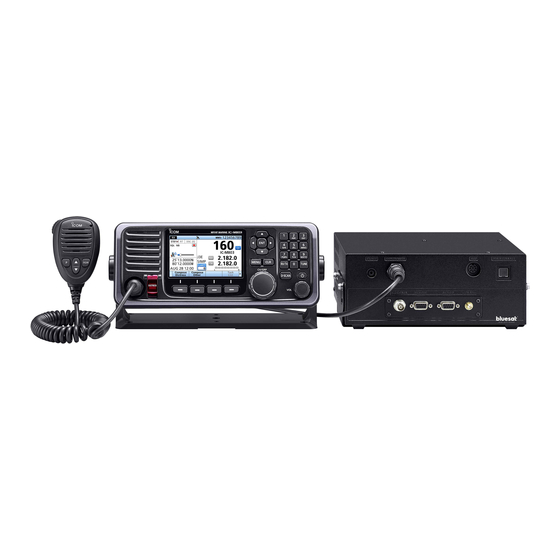
- Page 1 SERVICE MANUAL MF/HF MARINE TRANSCEIVER |M803 S-15612XZ-C1 March 2020...
- Page 2 Icom, Icom Inc. and the Icom logo are registered trademarks of Icom Incorporated (Japan) in Japan, the United States, the United Kingdom, Germany, France, Spain, Russia, Australia, New Zealand, and/or other countries.
-
Page 3: Table Of Contents
TABLE OF CONTENTS SECTION 1 SPECIFICATIONS SECTION 2 INSIDE VIEWS SECTION 3 DISASSEMBLY INSTRUCTION SECTION 4 INTERFACE INFORMATION SECTION 5 ADJUSTMENT PROCEDURE PREPARATION ……………………………………………………………………………………… 5-1 FREQUENCY ADJUSTMENT ……………………………………………………………………… 5-3 RECEIVE ADJUSTMENTS ………………………………………………………………………… 5-3 TRANSMIT ADJUSTMENTS ……………………………………………………………………… 5-4 BACKUP BATTERY FLOWING CURRENT VERIFICATION …………………………………… 5-6 DSC SELF CHECK TEST……………………………………………………………………………... -
Page 4: Specifications
SECTION 1 SPECIFICATIONS ■ GENERAL • Frequency coverage: Transceiver 0.5 ~ 29.9999 MHz (Continuously) 2.9999 MHz 4.9999 MHz 6.9999 MHz 8.9999 MHz 12.0 13.9999 MHz 16.0 17.9999 MHz 18.0 19.9999 MHz 22.0 22.9999 MHz 25.0 27.5000 MHz DSC receiver 2.1875 MHz, 4.2075 MHz, 6.3120 MHz, 8.4145 MHz, 12.5770 MHz, 16.8045 MHz •... -
Page 5: Inside Views
SECTION 2 INSIDE VIEWS • LOGIC UNIT (Remote Controller) J9151 J9401 (IC9121) J9051 9.8304 MHz FRONT CPU CRYSTAL OSCILLATOR (IC9001) (X9091) J9052 CLONING DATA INTERFACE (IC9402) RESET IC (IC9091) J9402 MIC AMPLIFIER (IC9301) J9201 J9091 8 V REGULATOR 3.3 V REGULATOR (IC9252) (IC9254) J9092... - Page 6 • MAIN UNIT FLASH ROM (IC5104) J4941 REAL TIME CLOCK IC (IC5081) J5102 REALTIME CLOCK BACKUP BATTERY (BT5081) ALC AMPLIFIER (IC5911) J5071 J5101 [MAINTENANCE] METER AMPLIFIER (IC5921) (IC4901) POWER SUPPLY CIRCUIT EEPROM (Under the shield cover) (IC5001) BUFFER (IC4072) J4141 [ACC] J4071 FPGA...
- Page 7 • PA UNIT POWER SUPPLY J6101 LINE SWITCH (Q6702) J6703 5 A FUSE BUFFER (F2) (IC6101) BUFFER (Q6101) BUFFER (IC6201) DRIVE AMPLIFIER DRIVE AMPLIFIER (Q6202) (Q6201) CURRENT SENSOR J6701 (IC6503) COOLING FAN DRIVER (Q6501) BUFFER (IC6401) BUFFER (IC6402) POWER AMPLIFIER POWER AMPLIFIER (Q6303) (Q6302)
- Page 8 • FILTER UNIT J7001 J7001 J7311 POWER/SWR SENSING CIRCUIT J7321...
- Page 9 • CONNECT UNIT NMEA1 INTERFACE (IC7751) J7751 [GPS-DATA] NMEA1 INTERFACE (IC7791) RS-232 INTERFACE (IC7723) NMEA1 INTERFACE RS-232 INTERFACE (IC7741) (IC7721) J7761 J7721 [REMOTE] RS-232 INTERFACE (IC7722) NMEA1 INTERFACE (IC7731) J7711 [AF/MOD] J7701 GPS MODULE (IC7701) 3.3 V REGULATOR W3010 (CHASSIS) (IC7702) [GPS-ANT] +3.3 V REGULATOR...
- Page 10 • DC-DC UNIT DC-DC CONVERTER CIRCUITS (Under the shield cover) 8 V DC-DC CONVERTER (IC9721) J9781 5 V REGURATOR (IC9751)
-
Page 11: Disassembly Instruction
SECTION 3 DISASSEMBLY INSTRUCTION 1. REMOVING THE PA UNIT 1) Remove the 8 screws from the top cover, and then 3) Remove the 8 screws from the PA cover, and then remove the top cover from the chassis. separate the PA cover from the chassis as shown in the illustration below. - Page 12 1. REMOVING THE PA UNIT (continued) 5) Remove the 11 screws from the 3 FETs and the 4 FET covers on the PA UNIT. 2. REMOVING THE MAIN UNIT 1) Remove the IC clip from the MAIN UNIT. Disconnect the control cable, 2 coaxial cables, and 3 flat Screws ×...
- Page 13 3. REMOVING THE CONNECT UNIT 4. REMOVING THE DC-DC UNIT 1) Remove the 6 screws from the bottom cover, and then Remove the 5 screws from the DC-DC UNIT, and then remove the bottom cover from the chassis. remove the DC-DC UNIT from the chassis. Screws ×...
- Page 14 6. REMOVING LOGIC UNIT 1) Remove the 8 screws from the rear case of the remote 3) Disconnect the speaker cable and 3 flat cables from the controller. LOGIC UNIT. Speaker cable Flat cable Screws × 8 Flat cables J9151 J9151 J9401 J9401...
-
Page 15: Interface Information
SECTION 4 INTERFACE INFORMATION • REMOTE CONTROLLER [MIC] [MIC] Description Specification number name MIC+ Audio input from the microphone element. Input impedance: 1.74 kΩ ±20% No connection. – 8-pin Audio output related to the volume setting. – Connected to pin 4 in the microphone. Audio input. - Page 16 • TRANSCEIVER FRONT PANEL (2) EXT-SP CONTROLLER MAINTENANCE [AF/MOD] [REMOTE] [GPS-DATA] [AF/MOD] AF/MOD Description Specification number name Input impedance: More than 600 Ω Modulation input from an external terminal MOD+ Input level: Approximately unit. 0.77 V rms MOD− Ground terminal for MOD+. –...
- Page 17 • TRANSCEIVER REAR PANEL [DC 13.6 V] [TUNER] [TUNER] TUNER Description Specification number name Key signal input. While tuning: −0.5~+0.8 V Pulled up 8 V, 0 V (100 msec) as a start START Start/Through signal output. signal. 13.6 V 13.6 V output. Maximum current: 2 A Rear panel view Ground terminal for above signals.
-
Page 18: Adjustment Procedure
Capacity: More than 150 W CONNECTIONS To [MAIN UNIT] IC-M803’s CONTROLLER Remote Control cable MICROPHONE HM-214H To [CONTROLLER] [MIC] IC-M803’s MAIN UNIT Audio millivoltmeter generator MICE Rear panel view [MIC] DC POWER SUPPLY #1 (13.6 V/30 A) To [ANT] To [DSC ANT] To [DC 13.6 V]... - Page 19 ENTERING THE I/O VERIFICATION MODE ENTERING THE ADJUSTMENT MODE 1. Turn OFF the power. 1. Turn OFF the power. 2. While holding down all [DISTRESS], [SOFT KEY 1], 2. While holding down all , and [▼] on the HM- and [►], turn ON the transceiver power to enter the I/O 214H, turn ON the transceiver power to enter the verification mode.
-
Page 20: Frequency Adjustment
5-2 FREQUENCY ADJUSTMENT Enter the adjustment mode. ADJUSTMENT ITEM ADJUSTMENT SETTING CONDITION OPERATION DISPLAY REFERENCE – • Three minutes have passed since Select the “REF OSC” item. FREQUENCY the transceiver is turned ON. (Adjustment menu: “REF OSC”) - Preparation - - Adjustment - 2 “REF OSC”... -
Page 21: Transmit Adjustments
5-4 TRANSMIT ADJUSTMENTS ADJUSTMENT ITEM ADJUSTMENT SETTING CONDITION OPERATION DISPLAY IDLING – – Select the “VDL IDL Set” item. - Preparation - (Adjustment menu: “TX/ID” > “ID” > “VDL IDL Set”) - Adjustment - 2 “VDL IDL Set” • Automatically transmits. Push ( Automatically returns to receive (Two beeps sound.) - Page 22 5-4 TRANSMIT ADJUSTMENTS (CONTINUED) ADJUSTMENT ITEM ADJUSTMENT SETTING CONDITION OPERATION DISPLAY TX OUTPUT 1 “TX Total MF Gain” • Receiving Push POWER (MF) 2 “TX Total MF Gain” • Automatically transmits. Rotate [CH/GRP] to set the output - Adjustment - power to 70 W, then push (Two beeps sound.) 3 “Power Tune (2.1M)”...
-
Page 23: Backup Battery Flowing Current Verification
5-5 BACKUP BATTERY FLOWING CURRENT VERIFICATION 1. Turn OFF the transceiver’s power. 2. Remove the top cover. (Refer to DISASSEMBLY INSTRUCTIONS in SECTION 3.) 3. Remove the backup battery (BT5081) from J5081 on the MAIN UNIT. 4. Apply 3.0 V DC to the point in the illustration shown below, through the digital multimeter. 5. -
Page 24: Parts List
SECTION 6 PARTS LIST [MAIN UNIT] [MAIN UNIT] PART PART DESCRIPTION DESCRIPTION LOCATION LOCATION IC4001 1110008540 S.IC 62783G-S18-R 130.5/111.3 Q5041 1590004690 S.TRA LDTC143ZET1G 158.5/50.4 IC4002 1110008540 S.IC 62783G-S18-R 118.3/111.8 Q5042 1530004140 S.TRA L2SC4081RT1G 155.8/51.1 IC4021 1110008550 S.IC NJM2904CRB1-TE1-#HMZR 107.6/109.1 Q5081 1510000502 S.TRA 2SA1162-GRLF 212.0/44.5... - Page 25 [MAIN UNIT] [MAIN UNIT] PART PART DESCRIPTION DESCRIPTION LOCATION LOCATION D5963 1750001810 S.DIO L1SS400T1G 195.7/97.2 L4702 6200010740 S.COI C2520C-R27G-A 3.7/94.0 D5971 1750001810 S.DIO L1SS400T1G 199.3/98.7 L4704 6200010960 S.COI C2520C-R47G-A (0.47U) 7.2/94.3 L4705 6200010960 S.COI C2520C-R47G-A (0.47U) 10.7/94.0 L4706 6200017540 S.COI NLV25T-101J-EF 16.2/89.1 FI5071 4580000260 S.FIL...
- Page 26 [MAIN UNIT] [MAIN UNIT] PART PART DESCRIPTION DESCRIPTION LOCATION LOCATION R4026 7030015970 S.RES RMC1/16S-103JTH (10 k) 113.0/105.1 R4405 7030016370 S.RES RMC1/16S-271JTH (270) 6.6/85.1 R4028 7030015970 S.RES RMC1/16S-103JTH (10 k) 111.2/106.1 R4406 7030016570 S.RES RMC1/16S-180JTH (18) 7.7/85.1 R4029 7030016380 S.RES RMC1/16S-183JTH (18 k) 111.2/105.1 R4407 7030016370 S.RES...
- Page 27 [MAIN UNIT] [MAIN UNIT] PART PART DESCRIPTION DESCRIPTION LOCATION LOCATION R4842 7030016210 S.RES RMC1/16S-121JTH (120) 61.7/90.9 R5168 7030016410 S.RES RMC1/16S-561JTH (560) 90.8/72.7 R4844 7030016560 S.RES RMC1/16SJPTH 59.7/112.8 R5181 7030015970 S.RES RMC1/16S-103JTH (10 k) 105.4/83.3 R4846 7030016210 S.RES RMC1/16S-121JTH (120) 60.7/114.7 R5182 7030016250 S.RES RMC1/16S-220JTH (22)
- Page 28 [MAIN UNIT] [MAIN UNIT] PART PART DESCRIPTION DESCRIPTION LOCATION LOCATION R5566 7030015910 S.RES RMC1/16S-101JTH (100) 110.4/46.6 C4012 4030025370 S.CER GRM033R61C104KE14D 135.9/104.8 R5573 7030015960 S.RES RMC1/16S-472JTH (4.7 k) 113.6/53.2 C4013 4030025370 S.CER GRM033R61C104KE14D 123.0/104.8 R5581 7030015910 S.RES RMC1/16S-101JTH (100) 101.6/58.8 C4021 4030022140 S.CER GRM033B31H102KA12D 111.1/111.3 R5582...
- Page 29 [MAIN UNIT] [MAIN UNIT] PART PART DESCRIPTION DESCRIPTION LOCATION LOCATION C4410 4030025370 S.CER GRM033R61C104KE14D 7.7/83.3 C4591 4030025420 S.CER GRM033R61A105ME15D 56.0/85.0 C4411 4030025370 S.CER GRM033R61C104KE14D 9.0/77.9 C4592 4030022080 S.CER GRM0332C1H101JA01D 56.8/79.4 C4421 4030025370 S.CER GRM033R61C104KE14D 10.1/60.1 C4593 4030022080 S.CER GRM0332C1H101JA01D 56.8/80.4 C4422 4030025370 S.CER GRM033R61C104KE14D 10.1/59.1 C4594 4030025040 S.CER GRM0332C1H220JA01D...
- Page 30 [MAIN UNIT] [MAIN UNIT] PART PART DESCRIPTION DESCRIPTION LOCATION LOCATION C4751 4030025370 S.CER GRM033R61C104KE14D 27.9/94.1 C4903 4030025370 S.CER GRM033R61C104KE14D 174.9/60.4 C4752 4030025420 S.CER GRM033R61A105ME15D 29.7/90.4 C4904 4030025370 S.CER GRM033R61C104KE14D 169.2/60.4 C4753 4030025310 S.CER GRM0332C1E102JA01D 28.9/94.1 C4905 4030025370 S.CER GRM033R61C104KE14D 162.3/53.4 C4754 4030022080 S.CER GRM0332C1H101JA01D 25.9/99.7...
- Page 31 [MAIN UNIT] [MAIN UNIT] PART PART DESCRIPTION DESCRIPTION LOCATION LOCATION C5244 4030022140 S.CER GRM033B31H102KA12D 104.3/94.3 C5508 4030025230 S.CER TMK107BJ105KAHT 85.5/27.8 C5245 4030022140 S.CER GRM033B31H102KA12D 106.3/89.2 C5521 4030019560 S.CER GRM21BB31C106KE15L 55.7/42.3 C5246 4030022160 S.CER GRM033B31A104KE84D 104.7/89.2 C5522 4030026000 S.CER GRM033R71E332KA12D 55.5/29.7 C5247 4030022140 S.CER GRM033B31H102KA12D 106.8/94.3...
- Page 32 [MAIN UNIT] PART DESCRIPTION LOCATION J5101 6510019971 S.CON 52808-1071 199.0/113.4 J5102 6510023980 S.CON 20R-JMCS-G-B-TF (NSA) 215.6/65.3 BT5081 3020000110 LIT CR-2032L/BK EP4001 6910019900 S.BEA MPZ1608S601AT 133.7/104.6 EP4002 6910019900 S.BEA MPZ1608S601AT 125.3/104.6 EP4051 6910019100 S.BEA MPZ1608S101AT 71.5/17.2 EP4052 6910019100 S.BEA MPZ1608S101AT 88.3/23.9 EP4053 6910019900 S.BEA MPZ1608S601AT 88.2/16.4...
- Page 33 [CONNECT UNIT] [CONNECT UNIT] PART PART DESCRIPTION DESCRIPTION LOCATION LOCATION IC7701 1190004602 S.IC GSU-141A-090E 93.8/8.5 C7714 4030025370 S.CER GRM033R61C104KE14D 69.0/13.3 IC7702 1180004740 S.REG S-1313D33-M5T1U3 98.3/23.2 C7715 4030025370 S.CER GRM033R61C104KE14D 66.2/13.3 IC7703 1180004740 S.REG S-1313D33-M5T1U3 100.1/16.8 C7716 4030025420 S.CER GRM033R61A105ME15D 100.8/19.2 IC7721 1120002921 S.IC ADM202EARNZ-REEL7 25.8/23.7...
- Page 34 [PA UNIT] [PA UNIT] PART PART DESCRIPTION DESCRIPTION LOCATION LOCATION IC6101 1110008550 S.IC NJM2904CRB1-TE1-#HMZR 164.5/16.9 R6412 7030015210 S.RES RMC1/16-472JTP (4.7 k) 111.3/36.1 IC6201 1110008550 S.IC NJM2904CRB1-TE1-#HMZR 153.5/16.9 R6413 7030015270 S.RES RMC1/16-153JTP (15 k) 108.9/34.6 IC6401 1110008550 S.IC NJM2904CRB1-TE1-#HMZR 114.1/26.2 R6414 7030015270 S.RES RMC1/16-153JTP (15 k) 111.3/33.5...
- Page 35 [PA UNIT] PART DESCRIPTION LOCATION C6610 4030024300 S.CER 0805B104K500CT 15.7/69.8 C6611 4030024340 S.CER 0805B472K500CT 15.7/71.7 C6612 4030024280 S.CER 0805B102K500CT 15.7/73.5 C6613 4510011390 ELE 16 ME 2200 WA C6701 4030023820 S.CER 0603B104K250CT 186.3/62.4 C6702 4030023820 S.CER 0603B104K250CT 186.3/66.2 C6703 4030023820 S.CER 0603B104K250CT 84.1/10.7 C6704 4030024040 S.CER 0603B472K500CT 104.5/18.3...
- Page 36 [FILTER UNIT] [FILTER UNIT] PART PART DESCRIPTION DESCRIPTION LOCATION LOCATION D7020 1750001810 S.DIO L1SS400T1G 137.5/93.4 C7108 4030021030 S.CER GRM31A5C2J181JW01D 150.0/40.2 D7361 1750000191 S.DIO 1SS322 (TE85RF) 165.3/81.8 C7109 4030018480 S.CER GRM31A5C2J221JW01D 174.1/40.0 D7362 1750000191 S.DIO 1SS322 (TE85RF) 165.4/88.5 C7110 4030018340 S.CER GRM31A5C2J331JW01D 176.2/40.0 C7111 4030021220 S.CER GRM31B5C2J681JW01L...
- Page 37 [FILTER UNIT] PART DESCRIPTION LOCATION C7511 4030024040 S.CER 0603B472K500CT 84.9/3.0 RL7001 6330002140 REL G5Q-1A DC5V RL7002 6330002140 REL G5Q-1A DC5V RL7003 6330002140 REL G5Q-1A DC5V RL7004 6330002140 REL G5Q-1A DC5V RL7005 6330002140 REL G5Q-1A DC5V RL7006 6330002140 REL G5Q-1A DC5V RL7007 6330002140 REL G5Q-1A DC5V RL7009 6330002140 REL...
- Page 38 [LOGIC UNIT] [LOGIC UNIT] PART PART DESCRIPTION DESCRIPTION LOCATION LOCATION IC9001 1140018911 S.IC STM32F429IIT6 75.6/47.0 R9094 7030016560 S.RES RMC1/16SJPTH 70.3/30.5 IC9051 1190003620 S.IC TPS61161ADRVR 39.5/80.3 R9095 7030016560 S.RES RMC1/16SJPTH 73.5/31.9 IC9071 1190003620 S.IC TPS61161ADRVR 39.5/68.0 R9096 7030016060 S.RES RMC1/16S-105JTH (1 M) 72.6/31.9 IC9091 1110005771 S.IC S-80942CNMC-G9CT2G...
- Page 39 [LOGIC UNIT] [LOGIC UNIT] PART PART DESCRIPTION DESCRIPTION LOCATION LOCATION C9038 4030024900 S.CER GRM033R61A224KE90D 60.0/55.7 J9151 6510014961 S.CON B2B-ZR-SM4-TF (LF) (SN) 6.9/34.1 C9039 4030022140 S.CER GRM033B31H102KA12D 69.8/32.0 J9201 6510022031 S.CON B10B-ZR-SM4-TF (LF) (SN) 151.1/84.2 C9041 4030025040 S.CER GRM0332C1H220JA01D 76.4/52.8 J9401 6510022621 S.CON 10FMN-BMTTR-A-TBT (LF) (SN) 7.7/19.3 C9051...
- Page 40 [DIAL UNIT] PART DESCRIPTION LOCATION J8501 6510029480 S.CON 06FH-SM1-TB (LF) (SN) 5.0/2.2 S8501 2250000930 ENC ED09D21MFB14.5A6C102016 Eqv.= This component is equivalent to the REF No. component listed above, M.= Mounted side (T: Mounted on the Top side, B: Mounted on the Bottom side) and may be substituted on parts orders and repairs.
- Page 41 [VOL UNIT] PART DESCRIPTION LOCATION J8501 6510029480 S.CON 06FH-SM1-TB (LF) (SN) 5.0/2.2 S8501 2250000930 ENC ED09D21MFB14.5A6C102016 Eqv.= This component is equivalent to the REF No. component listed above, M.= Mounted side (T: Mounted on the Top side, B: Mounted on the Bottom side) and may be substituted on parts orders and repairs.
- Page 42 10.2/20.8 C8568 4030022140 S.CER GRM033B31H102KA12D 16.7/17.0 J8561 6510030290 CON ICOM-CCBPM08MCC J8562 6510022621 S.CON 10FMN-BMTTR-A-TBT (LF) (SN) 20.9/11.0 Eqv.= This component is equivalent to the REF No. component listed above, M.= Mounted side (T: Mounted on the Top side, B: Mounted on the Bottom side) and may be substituted on parts orders and repairs.
- Page 43 [JACK UNIT] PART DESCRIPTION LOCATION J8601 6510020711 S.CON 52793-1070 32.7/14.3 J8602 6450001630 CON HSJ1406-01-050 Eqv.= This component is equivalent to the REF No. component listed above, M.= Mounted side (T: Mounted on the Top side, B: Mounted on the Bottom side) and may be substituted on parts orders and repairs.
- Page 44 [DC-DC UNIT] [DC-DC UNIT] PART PART DESCRIPTION DESCRIPTION LOCATION LOCATION IC9671 1180003460 S.REG NJM2831F05-TE1-#ZZZB 22.6/64.4 C9786 4030025370 S.CER GRM033R61C104KE14D 77.0/54.2 IC9672 1130012160 S.IC SN74LVC1GU04DCKR 23.5/60.5 C9787 4030025370 S.CER GRM033R61C104KE14D 93.3/54.2 IC9673 6910026640 S.DC MP2224GJ-P 23.0/57.0 IC9691 1180004960 S.REG XC6230H001QR-G 40.0/56.5 IC9701 1130012160 S.IC SN74LVC1GU04DCKR 27.0/82.0...
-
Page 45: Mechanical Parts
SECTION 7 MECHANICAL PARTS [CHASSIS UNIT] [PA UNIT] PART PART DESCRIPTION QTY. DESCRIPTION QTY. J3001 6510028411 MR-DS-01-2 J6101* 6510028210 SJ050010 (TMP-J01X-V6) J3003 6510028411 MR-DS-01-2 J6401* 6510028210 SJ050010 (TMP-J01X-V6) MF3001 2710001060 FD128025HB-N (2N7R1) F6701* 5220000440 FHA040-01 F6702 5210001430 11930011 (BFLP 5A 58V) W3001 8900011050 OPC-1109 W3002 8920003240 CAB-1390... - Page 46 EP1001 0800016040 AA.162.501111.IB PART DESCRIPTION QTY. MP1001 8010018981 2429 BRACKET-1 J8561 6510030290 ICOM-CCBPM08MCC MP1002 8810001490 PH A M5×20 SUS MP1003 8850000500 S-WASHER M5 SUS MP1004 8850000180 FLAT WASHER M5 SUS MP1005 8810009300 SET SCREW (J) MP1006 8950007250 3054 MIC HANGER MP1007 8810004700 PH A M3×16 SUS...
- Page 47 Used grease: G501 (80G) SHINETSU (8950002750) MP8024 (FRONT) × 8 (8820001180) Torque: 0.7 N·m (±0.1 N·m) (Comes with W8007 (FRONT)) Tighten with: “ICOM Driver (V)” (8960000430) Torque: 1.0 N·m (±0.15 N·m) MP8001 (FRONT) Washer (Comes with W8007 (FRONT)) W8007 (FRONT) (8920001660) MP8025 (FRONT) ×...
- Page 48 MP3025 (CHASSIS) × 4 MP3012 (CHASSIS) × 8 (8810007231) (8810008661) MP3025 (CHASSIS) × 4 (8810007231) Torque: 0.7 N·m (±0.1 N·m) Legend: Ref.No. Unit Name MP3028 (CHASSIS) MP1 (CHASSIS) MP6404 (PA) MP6403 (PA) (8810007231) (1234567890) (8860001640) (8860001640) MP3002 (CHASSIS) MP6401 (PA) MP6402 (PA) MP3026 (CHASSIS) (8110007703)
-
Page 49: Board Layouts5
SECTION 8 BOARD LAYOUTS The actual configuration of the PC board can be seen by viewing the top and bottom BOARD LAYOUT pages together. • LOGIC UNIT (B-9011B: TOP VIEW) J9053 S9076 DS9084 S9083 S9084 S9085 DS9001 DS9085 DS9086 DS9078 S9077 S9079 S9078... - Page 50 The actual configuration of the PC board can be seen by viewing the top and bottom BOARD LAYOUT pages together. • LOGIC UNIT (B-9011B: BOTTOM VIEW) J9201 J9051 B9011B J9052 J9051 J9052 J9201 FOR MAIN R9202 C9060 C9059 J9201 R9059 C9058 Q9051 R9060...
- Page 51 The actual configuration of the PC board can be seen by viewing the top and bottom BOARD LAYOUT pages together. • DIAL/VOL UNIT (B-9012: TOP VIEW) • DIAL/VOL UNIT (B-9012: BOTTOM VIEW) • MIC UNIT (B-9014B: TOP VIEW) • MIC UNIT (B-9014B: BOTTOM VIEW) D8562 C8568 MISW...
- Page 52 The actual configuration of the PC board can be seen by viewing the top and bottom BOARD LAYOUT pages together. • CONNECT UNIT (B-9008C: TOP VIEW) J7761 B9008C J7761 J7761 Q7792 Q7791 RL7721 RL7722 R7730 R7791 R7729 IC7791 R7792 R7749 J7701 C7753 R7731...
- Page 53 The actual configuration of the PC board can be seen by viewing the top and bottom BOARD LAYOUT pages together. • CONNECT UNIT (B-9008C: BOTTOM VIEW) J7711 J7721 [AF/MOD] [REMOTE] See the PARTS LIST H/V location on the PARTS LIST for location details.
- Page 54 The actual configuration of the PC board can be seen by viewing the top and bottom BOARD LAYOUT pages together. • MAIN UNIT (B-9007B: TOP VIEW) J4001 J4071 C4803 R4796 C4861 C4830 C4759 R4816 C4862 J4001 J4071 R4756 R4846 C4779 C4881 C4802 R4776...
- Page 55 The actual configuration of the PC board can be seen by viewing the top and bottom BOARD LAYOUT pages together. • MAIN UNIT (B-9007B: BOTTOM VIEW) J4161 [EXT-SP] J4141 [ACC] See the PARTS LIST H/V location on the PARTS LIST for location details.
- Page 56 The actual configuration of the PC board can be seen by viewing the top and bottom BOARD LAYOUT pages together. • PA UNIT (B-9009B: TOP VIEW) B-9009B J6501 Q6301 MP6401 J6501 R6519 C6513 D6308 F6702 J6501 C6311 F6701 R6321 R6701 C6302 C6334 C6609...
- Page 57 The actual configuration of the PC board can be seen by viewing the top and bottom BOARD LAYOUT pages together. • PA UNIT (B-9009B: BOTTOM VIEW) See the PARTS LIST H/V location on the PARTS LIST for location details.
- Page 58 The actual configuration of the PC board can be seen by viewing the top and bottom BOARD LAYOUT pages together. • DC-DC UNIT (B-9088A: TOP VIEW) C9735 C9730 R9723 R9724 C9723 C9729 IC9721 L9721 C9733 C9722 R9701 C9717 C9701 C9718 C9709 C9716 C9704...
- Page 59 The actual configuration of the PC board can be seen by viewing the top and bottom BOARD LAYOUT pages together. • DC-DC UNIT (B-9088A: BOTTOM VIEW) H3R3V See the PARTS LIST H/V location on the PARTS LIST for location details. 8-11...
- Page 60 The actual configuration of the PC board can be seen by viewing the top and bottom BOARD LAYOUT pages together. • FILTER UNIT (B-9010B: TOP VIEW) B9010B J7311 L7017 R7017 RL7018 C7017 C7021 C7020 RL7017 L7016 R7016 D7020 R7015 R7013 C7371 L7015 R7014...
- Page 61 The actual configuration of the PC board can be seen by viewing the top and bottom BOARD LAYOUT pages together. • FILTER UNIT (B-9010B: BOTTOM VIEW) See the PARTS LIST H/V location on the PARTS LIST for location details. 8-13...
-
Page 62: Wiring Diagram
SECTION 9 WIRING DIAGRAM DC-DC UNIT J7751 [GPS-DATA] J7711 MOD+ W3012 MOD- [AF/MOD] NSEND W3011 J7761 J4051 J7721 [DSC-ANT] CONNECT UNIT DSEN DSEN DSAF DSAF J4701 J3003 DSAFE W3008/W3009 DSAFE DSMD DSMD [REMOTE] DSMDE DSMDE GRESL GRESL [ANT] H3R3V J7501 H3R3V J4001 W3007... -
Page 63: Block Diagram
SECTION 10 BLOCK DIAGRAM IC9254 IC9301 +3.3V IC9252 H13V FMOD MUTE H13V Q9408 TO MAIN UNIT FAFMS MUTE IC9402/Q9402/Q9405 CTRL LTXD LRXD JACK UNIT CLONE ICFRXD/ICFTXD LRXD LTXD VOL UNIT IC9071/D9071 DRIVER DS9071~DS9086 X9091 DIAL UNIT 9.8304MHz DS9001 IC9001 FRONT MODULE DIAL-A,B,P IC9121... - Page 64 MAIN UNIT(5/9) MAIN UNIT(1/9) for the schematic. for the schematic. MAIN UNIT(2/9) MAIN UNIT(9/9) for the schematic. for the schematic. MAIN UNIT(7/9) Q5931/Q5932 for the schematic. IC5101 IC5911/Q5911 IC5401 FPGA Q4142 NASBS ALC-CTRL [ACC] KEYIN IC9673 IC9691 IC5911 J4006 (13.6V) H3R3V H3R3V MAIN CPU...
- Page 65 MAIN UNIT(5/9) MAIN UNIT(6/9) MAIN UNIT(4/9) for the schematic. for the schematic. for the schematic. DSC ANT FP1R1V FP2R5V DA3R3V 2MHz BAND fc=18MHz DB1S DPOFS DPOF13 CTRL 4MHz BAND Q4701/Q4702 D4703 Q4871/Q4872 REV-PWR CTRL DB2S Q4881 6MHz BAND DPONS DPON13 CTRL DPR8 DB3S...
- Page 66 [ANT] 43MHz TO MAIN UNIT 1.6~2MHz RL402 RL401 IC6401 PFID4V BUFF 2~3MHz TO MAIN UNIT D7361/D7362 RL402 RL401 IC6401 PWR/SWR PFID3V BUFF 3~5MHz RL352 RL351 IC6402 IC6201 PDID2V BUFF PFID2V BUFF IC6101 IC6402 IC6201 RL252 RL251 BUFF PPID1V PDID1V BUFF PFID1V BUFF TO MAIN UNIT...
-
Page 67: Voltage Diagram1
SECTION 11 VOLTAGE DIAGRAM • LOGIC UNIT Explanatory notes TX Line TO MIC UNIT R9321 RX Line R9410 LTXD Voltage Line EP9401 MPZ2012S331A R9409 C9402 100 CV C9313 TO MAIN UNIT MICE EP9402 MPZ2012S102A 120P C9305 R9314 EP9403 MPZ2012S102A R9315 J9201 R9316 PTTE... - Page 68 • DIAL UNIT TO LOGIC UNIT J8501 ED09D21MFB14.5A6C102016 S8501 DIAL-A DIAL-A DIAL-B DIAL-B DIAL-P DIAL-P • JACK UNIT TO LOGIC UNIT J8601 J8602 PHO1 PHO1 PMUT1 PMUT1 PMUT2 PMUT2 PHO2 PHO2 • MIC UNIT MIC&HANDSET TO LOGIC UNIT J8561 J8562 MICE MICSW MICSW...
- Page 69 • MAIN UNIT (1/9) Explanatory notes MAIN UNIT(2/9) TX Line H3R3V H3R3V 3R3V 3R3V RX Line Voltage Line REFLP Measuring condition: MAIN UNIT(9/9) (unless otherwise noted) D4023 FORLP • Frequency: 12.23 MHz • Mode: J3E (USB) R4024 LRB706F D4024 • RX: No signal is received. IC4022 D4021 R4031...
- Page 70 • MAIN UNIT (2/9) MAIN UNIT(1/9) Explanatory notes H3R3V H3R3V MAIN UNIT(1/9 and 1/5) TX Line H3R3V RX Line Voltage Line DCLK_P MAIN UNIT(7/9) FP1R1V FP1R1V MAIN UNIT(7/9) DCLK_N IC4321 R4321 FP2R5V VOUT FP2R5V MAIN UNIT(6/9 and 7/9) MAIN UNIT(5/9) PWRSR XC6222D251MR IC4331...
- Page 71 • MAIN UNIT (3/9) MAIN UNIT(2/9) R4428 R4691 R4692 ~1.599999 MHz 13.3 D4451 L4452 L4453 C4455 D4452 R4404 1.600000 MHz~ 1SV308 5.6U 4.7U 0.047 1SV308 Q4402 Q4401 C4453 LDTC143ZE LDTA114YE HPOFS HPOFS 270P Q4632 Q4631 J4401 LDTC143ZE MAIN UNIT(5/9) IC4401 LDTA114YE L4402 C4409...
- Page 72 • MAIN UNIT (4/9) MAIN UNIT(2/9) C4874 C4872 DPOFS MAIN UNIT(5/9) Q4871 LDTA114YE Q4872 D4731 C4731 L4733 C4734 L4735 C4736 L4739 C4738 D4732 0.18U 0.27U LDTC143ZE L4701 L4702 0.22U 1SV308 820P 820P 1SV308 J4701 C4864 0.47U 0.47U 0.47U C4703 C4709 C4711 L4704 L4705...
- Page 73 • MAIN UNIT (5/9) MAIN UNIT(2/9) H3R3V H3R3V H3R3V DCSYNCS DCSYNCS R5071 USB_VBUS PWRSR MAIN UNIT(2/9) PWRSR 4.7K MAIN UNIT(3/9) J5071 FI5071 NASBS NASBS MAIN UNIT(9/9) USB_DP USB_DM RPPS MAIN UNIT(1/9) RPPS MMODS MMODS MAIN UNIT(8/9) EXC24CF900 D5071 EP5071 RCLAMP7524T MMZ1005B601C DA3R3V SLFS...
- Page 74 • MAIN UNIT (6/9) 3R3V IC5161 VOUT 3R3V 3R3V 1R8V DA3R3V 1R8V MAIN UNIT(1~5,7~9/9) XC6209F502MR 1R8V 1R8V IC5101 5CEFA9F23I7N DA3R3V ATDO EP5162 nCSO VREFB3AN0 ATMS DA3R3V MMZ1005Y102CT VCCIO3A VPGM MAIN UNIT(7/9) AS_DATA3 VCCIO3A FP2R5V ATCK DIFFIO_TX_B8p C5166 R5181 AS_DATA2 PR_ERROR/DIFFIO_RX_B7p FP2R5V ATDI PR_READY/DIFFIO_TX_B8n...
- Page 75 • MAIN UNIT (7/9) DA3R3V DA3R3V DA3R3V DA3R3V DA3R3V MMZ1005Y102CT 13.6 ns (73.728 MHz) FP2R5V R5451 FP2R5V MAIN UNIT(2/9) FP1R1V 2.3 Vp-p IC5451 IC5101 5CEFA9F23I7N G10 DIFFIO_RX_T49p VREFB8AN0 FP1R1V L7 DIFFIO_TX_T50p/T_A_0 VCCIO8A ADCLK_P F10 DIFFIO_RX_T49n VCCIO8A K7 DIFFIO_TX_T50n/T_A_1 SN65LVDS1DBV VCCIO8A R5442 J7 DIFFIO_RX_T51p/T_A_4 VCCIO8A...
- Page 76 • MAIN UNIT (8/9) AFONS MAIN UNIT(1/9) DA5V DA5V DA5V DA5V DA3R3V 13.3 L5601 LW-15 MCLK MCLK BCLK R5525 2.7k BCLK /FPCAL C5524 820P /FPCAL DX_AFO DX_AFO R5522 R5524 DX_ACC IC5521 DX_ACC R5604 R5526 C5525 C5604 DX_REFC DX_REFC 5.6k C5615 DX_AGC DX_AGC DR_AMOD...
- Page 77 • MAIN UNIT (9/9) MAIN UNIT(2/9) -12V –12V R5902 D5901 R5931 LDTA114YE Q5901 180K LDTC143ZE L1SS400 Q5932 R5932 Q5902 R5903 NASBS 470K RU1L002SN 220K R5904 C5910 4.7K 100P R5912 MAIN UNIT(3/9) 120K R5913 C5955 C5954 R5914 Q5911 IC5911 C5956 L2SC4081 NJM2058V C5957 C5912...
- Page 78 • PA UNIT R6322 C6335 C6313 R6323 R6318 RD100HHF1C Q6304 C6309 R6319 R6310 C6333 C6331 RD100HHF1C Q6303 R6207 R6311 C6303 J6401 R6108 L6408 FLIN C6201 Q6201 LA-262 RD15HVF1 RD06HVF1 Q6101 J6101 R6101 LR-360 C6103 L6101 L6201 L6302 L6301 L6102 LR-361 C6202 LR-530 Q6202...
- Page 79 • FILTER UNIT RL7001 RL7011 L7102 1.6~1.9999 MHz L7101 Explanatory notes L7103 LR-226 Measuring condition: (unless otherwise noted) LR-236 C7109 LR-227 TX Line R7001 L7001 L7011 R7011 C7103 220P C7115 RX Line • Frequency: 12.23 MHz C7110 470P C7104 330P C7116 •...
- Page 80 • CONNECT UNIT EP7701 J7701 MPZ2012S101A FI7701 TA0757B IC7701 R7701 R7702 C7720 A1 RF_IN A5 VDD_BKUP_IN VDD_BKUP_BAT_IN I2C_SCL [GPS ANT] GPIO0 I2C_SDA IC7702 B4 UART0_RX IC7703 B5 UART0_CTS ON/OFF VDD_PRPH_OUT VOUT B7 UART0_T X 3 ON/OFF VOUT S-1313D33 S-1313D33 NRST C5 BOOT_MODE0 C6 VDD_IO_HOST CP7704...
- Page 81 • DC-DC UNIT 13.4 13.4 R9673 IC9671 CTRL IC9691 VOUT VOFB MPZ2012S601A ILIM NJM2831F05 L9671 EP9671 VOUT 3.3U XC6230H001QR R9671 C9676 DCLK_P SN74LVC1GU04DCKR H3R3V IC9672 MP9671 3183 R9701 DCLK_P SN74LVC1GU04DCKR L9701 TO MAIN IC9701 J9781 3.3U EP9781 C9704 MPZ2012S601A EP9788 EP9701 MPZ2012S101A R9705...
- Page 82 If you have any inquiries regarding service, contact your distributor. The contact number or E-mail address of your distributor can be found on our website. https://www.icomjapan.com/...
- Page 83 S-15612XZ-C1 1-1-32, Kamiminami, Hirano-ku, Osaka 547-0003, Japan © 2020 Icom Inc.
Need help?
Do you have a question about the IC-M803 and is the answer not in the manual?
Questions and answers