
Subscribe to Our Youtube Channel
Related Manuals for Icom IC-M85UL


Summary of Contents for Icom IC-M85UL
- Page 1 INSTRUCTION MANUAL VHF MARINE TRANSCEIVER iM85UL This device complies with Part 15 of the FCC Rules. Operation is subject to the condition that this device does not cause harmful interference.
-
Page 2: Explicit Definitions
IN CASE OF EMERGENCY Thank you for choosing this Icom product. This product is designed and built with Icom’s state of the art technology and craftsmanship. With proper care, If your vessel requires assistance, contact other vessels and the this product should provide you with years of trouble-free Coast Guard by sending a Distress call on Channel 16. -
Page 3: Precautions
• The use of Icom transceivers with any equipment that is not manufactured or approved by Icom. CAUTION: DO NOT use harsh solvents such as Benzine or alcohol when cleaning. -
Page 4: Précautions (Pour Le Canada)
Man Down, Lone Worker et MOB sont très forts. bouche de l’utilisateur et quand l’appareil est vertical. Icom n'est pas responsable de la destruction ou des dommages sur R AVERTISSEMENT! NE JAMAIS utiliser l'émetteur-récepteur l'é metteur-récepteur Icom, si le dysfonctionnement est causé par: avec un casque ou tout autre accessoire audio à... -
Page 5: Table Of Contents
TABLE OF CONTENTS IMPORTANT ..................i 8 OTHER FUNCTIONS ...............18 ■ Using the LAND channel group ...........18 EXPLICIT DEFINITIONS ..............i ■ Using the Voice Scrambler ..........18 IN CASE OF EMERGENCY ............i RECOMMENDATION ..............i ■ Checking the battery health and battery cycle .....18 PRECAUTIONS ................ii 9 SET MODE ................19 PRÉCAUTIONS (pour le Canada)...........iii... -
Page 6: Operating Rules
OPERATING RULES D Priorities (2) OPERATOR’S LICENSE • Read all rules and regulations pertaining to call priorities, A Restricted Radiotelephone Operator Permit is the license and keep an up-to-date copy handy. Safety and distress most often held by small vessel radio operators when a calls take priority over all others. -
Page 7: Accessories
ACCESSORIES ■ Supplied accessories ■ Attaching accessories D Flexible antenna Belt clip Handstrap Battery pack Antenna Connect the supplied flexible antenna to the antenna connector. Battery charger Power adapter (With a screw) (For Battery charger) CAUTION: • DO NOT carry the transceiver by holding only the antenna. NOTE: Some accessories are not supplied, or the shape is •... - Page 8 ACCESSORIES D Battery pack To detach: CAUTION: DO NOT attach or detach the battery pack when the transceiver is wet or soiled. This may result in Pull both battery sliding locks in the direction of the water or dust getting into the transceiver/ battery pack and arrow.
- Page 9 ACCESSORIES D Belt clip To attach: To detach: Remove the battery pack from the transceiver, if it is Lift the tab up (q), and slide the belt clip in the direction of attached. the arrow (w). 2. Slide the belt clip in the direction of the arrow until the BE CAREFUL! DO NOT break your fingernail.
-
Page 10: Panel Description
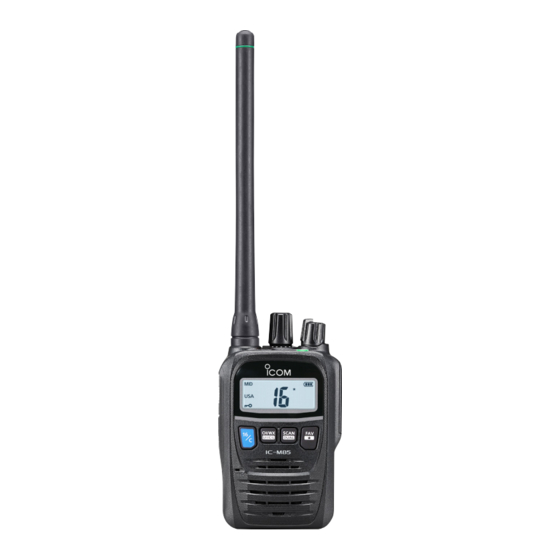
PANEL DESCRIPTION ■ Front, top and side panels t TRANSMIT POWER KEY [H/L] z Push to set the power level to high, mid, or low. L Some channels are set to only low power. z Hold down for 1 second to display the battery health Antenna and battery cycle. -
Page 11: Function Display
PANEL DESCRIPTION ■ Function display “ ” FAVORITE CHANNEL ICON Displayed when a Favorite channel is selected. (p. 16) SCAN INDICATOR “SCAN” Blinks while scanning. (p. 15) CALL CHANNEL INDICATOR “CALL” Displayed when the Call channel is selected. (p. 11) TRANSMIT POWER INDICATOR “MID”/“LOW”... -
Page 12: Battery Charging
If buildup in the battery cells, such as could occur near fires or any of these conditions occur, contact your Icom dealer or stoves, inside a sun-heated vehicle, or in direct sunlight for distributor. -
Page 13: Charging Caution
BATTERY CHARGING CAUTION: DO NOT leave the pack fully charged, ■ Charging caution completely discharged, or in an excessive temperature environment (above 50°C, 122°F) for an extended period of R DANGER! NEVER charge the battery pack in areas with time. If the battery pack must be left unused for a long time, extremely high temperatures, such as near fires or stoves, it must be detached from the transceiver after discharging. -
Page 14: Battery Charger
BATTERY CHARGING ■ Battery charger D Optional BC-226 desktop charger Charging time: approximately 2.7 hours D Supplied battery charger Charging time: approximately 2.7 hours Battery pack Turn OFF Battery pack Power adapter* Turn OFF Power adapter* Battery charger BC-226 Status indicator Status indicator L To connect the power adapter to the charger, remove the... - Page 15 BATTERY CHARGING D Information Connecting BC-226 together You can connect up to 6 BC-226 together. Remove the charger’s right cover. (q) Status indicator 2. Snap the DC power plug to the other charger’s DC Light color Status power jack. (w) Orange Charging Green...
-
Page 16: Basic Operation
BASIC OPERATION ■ Selecting a channel D Channel 16 Setting the Call channel By default, a Call channel is set in each Channel Group. Channel 16 is the distress and safety channel. It is used for You can set your most often-used channel as your Call establishing initial contact with a station, and for emergency channel in each Channel Group for a quick recall. - Page 17 BASIC OPERATION Setting the Weather Alert D Changing channel group Turn OFF the transceiver. Channel Groups are preset into your transceiver. You can 2. While holding down [SQL], Turn ON the transceiver to select the Channel Group between USA, International, and enter the Set mode.
-
Page 18: Receiving And Transmitting
BASIC OPERATION ■ Receiving and transmitting CAUTION: Transmitting without an antenna will damage NOTE: the transceiver. • To conserve battery power, the Power Save function automatically turns ON when no signal is received for 5 NOTE: Before using the transceiver for the first time, the seconds. -
Page 19: Adjusting The Squelch Level
BASIC OPERATION ■ Using the AquaQuake water ■ Adjusting the squelch level draining function The squelch enables the audio to be heard only while receiving a signal that is stronger than the set level. A higher Water in the speaker grill may muffle the sound coming level blocks weak signals, so that you can receive only from the speaker. -
Page 20: Scan
SCAN ■ Scan types You can find ongoing calls by scanning the Favorite channels. PRIORITY SCAN Before starting a scan, you need to: A Priority scan sequentially scans all Favorite channels • Set the channels that you want to scan as Favorite while monitoring Channel 16. -
Page 21: Favorite Channels
SCAN OPERATION ■ Favorite channels ■ Starting a scan You can quickly recall often-used channels by setting them Push [SCAN] to start a scan. as Favorite channels. • During a Normal scan, “SCAN” blinks. • During a Priority scan, “ ” is also displayed. D Setting/Clearing L When a signal is received, the scan pauses until the signal Rotate [DIAL] to select a channel. -
Page 22: Dualwatch/Tri-Watch
DUALWATCH/TRI-WATCH ■ Description ■ Operation Dualwatch and Tri-watch are convenient to monitor Channel Select Dualwatch or Tri-watch in the Set mode (p. 20). 16 while you are operating on another channel. 2. Select a channel. 3. Hold down [DUAL] for 1 second to start Dualwatch or Tri-watch. -
Page 23: Other Functions
The default setting of the LAND channel group is the same • Displayed for 5 seconds. as that of the INT channel group. Ask your local Icom L The battery health is indicated by the status indicator. dealer for the LAND channel group setting and LMR/PMR frequency setting details. -
Page 24: Set Mode
SET MODE ■ Using the Set mode Turn OFF the transceiver. You can set seldom changed settings in the Set mode. 2. While holding down [SQL], turn ON the transceiver to You can customize the transceiver settings to suit your enter the Set mode. -
Page 25: Set Mode Items
SET MODE ■ Set mode items D Scan Timer “ ” NOTE: The Set mode items contained in the transceiver Turns the Scan Resume Timer ON or OFF. may be different, depending on the transceiver’s version or • OFF: When a signal is detected on a channel, the scan presettings. - Page 26 SET MODE ■ Set mode items (Continued) D CH Display “ ”/“ ”/“ ”/“ ” D SQL Key Action “ ” Selects the number of digits to display the channel number. The function temporarily opens the squelch. You can select settings for each channel group. •...
- Page 27 SET MODE D Lone Worker Alarm “ ” D AquaQuake Action “ ” Turns the Lone Worker Alarm ON or OFF. Selects whether or not to activate the AquaQuake water If no operation occurs for the preset period of time, an alarm draining function by shaking the transceiver.
-
Page 28: Specifications And Options
SPECIFICATIONS AND OPTIONS ■ Specifications D Transmitter All stated specifications are subject to change without notice • Output power: or obligation. Marine 5 W (Hi), 3 W (Mid), and 1 W (Low) LMR (USA) 2 W (Hi), 1 W (Low) D General LMR (Export) 5 W (Hi), 3 W (Mid), and 1 W (Low) -
Page 29: Options
SPECIFICATIONS AND OPTIONS ■ Options D Battery pack • BC-225 + BC-123S intelligent desktop charger ac adapter • BP-292UL i-ion battery pack + RS-BC225 reader software Voltage: 7.2 V For rapidly charging battery packs. Capacity: 1910 mAh (minimum), 2010 mAh (typical) You can check the charging status using the RS-BC225. -
Page 30: Using The Hm-184Ul
SPECIFICATIONS AND OPTIONS ■ Using the HM-184UL To attach: Attach the connector of the speaker microphone to Alligator type clip the multi connector on the transceiver and tighten the screw. Turn OFF [PTT] Screw Microphone Speaker Coin Turn OFF the transceiver before attaching or detaching the microphone NOTE: CAUTION: Firmly attach to... -
Page 31: Vhf Marine Channel List
VHF MARINE CHANNEL LIST Channel number Frequency (MHz) Channel number Frequency (MHz) Channel number Frequency (MHz) Channel number Frequency (MHz) CAN Transmit Receive CAN Transmit Receive CAN Transmit Receive CAN Transmit Receive 156.050 160.650 157.000 157.000 64A 156.225 156.225 157.175 161.775 156.050 156.050 Rx only 161.600 156.275 160.875... -
Page 32: Troubleshooting
TROUBLESHOOTING PROBLEM POSSIBLE CAUSE SOLUTION REF. The transceiver does • The battery is exhausted. • Recharge the battery pack. p. 9 not turn ON. • The battery pack is not correctly attached. • Correctly reattach the battery pack. p. 3 Little or no sound •... -
Page 33: Ul Information
Model Number BP-292UL manufactured by • Standards of safety: ANSI/ISA 12.12.01-2015 Icom Inc. only. Use of another battery may present a risk of CAN/CSA C22.2 No.213-15 fire or explosion. CAUTION: Risk of fire and burns. Do not open, crush, heat This equipment is suitable for use in Class I, Division 2, above +60°C (+140°F) or incinerate. -
Page 34: Firmware Version Identification
MISE EN GARDE: Tout changement ou modification, equipment is operated in a commercial environment. This non expressément approuvé par Icom Inc., peut annuler equipment generates, uses, and can radiate radio frequency l'autorisation de l'utilisateur à utiliser cet appareil energy and, if not installed and used in accordance with the conformément à... -
Page 35: Information
FCC and IC RF exposure limits for “Occupational Recommended Practice for the Measurement of Potentially Use Only”. In addition, your Icom radio complies with the Hazardous Electromagnetic Fields– RF and Microwave. following Standards and Guidelines with regard to RF energy and electromagnetic energy levels and evaluation of •... - Page 36 [PTT] switch. • ALWAYS keep the antenna at least 2.5 cm (1 inch) away from the body when transmitting and only use the Icom belt-clips which are listed on page 12 when attaching the radio to your belt, or other place, to ensure FCC and IC RF exposure compliance requirements are not exceeded.
-
Page 37: Infomation En Matiére De Sécurité
RF de la FCC et d’IC, pour une «utilisation grand public». micro-ondes. En outre, votre radio Icom satisfait les normes et directives qui suivent en matière de niveaux d’énergie et d’énergie • Les accessoires illustrés dans “Options” de la feuille électromagnétique de RF et d’évaluation de tels niveaux en... - Page 38 • TOUJOURS tenir l'antenne éloignée d'au moins 2,5 cm de votre corps au moment d'émettre et utiliser uniquement l'attache pour ceinture Icom illustrée à la p. 12, lorsque vous attachez la radio à votre ceinture, ou à autre chose, de façon à vous assurer de ne pas provoquer une exposition aux RF supérieure aux limites fixées...
- Page 39 INDEX VOX Delay......21 Accessories Operating rules ......1 Options .........24 VOX Level ......21 Attaching ......2 WX Alert .......20 Supplied .......2 Specifications........23 AquaQuake ........14 Panel description ......5 Squelch .........14 Backlight ........21 Receiving ........13 Basic operation ......11 Transmitting ........13 Troubleshooting ......27 Battery ..........7 Scan Battery cycle ......18 Normal scan ......15...
- Page 40 AXXXXX-1EX Printed in Japan 1-1-32 Kamiminami, Hirano-ku, Osaka 547-0003, Japan 2018 Icom Inc. ©...
Need help?
Do you have a question about the IC-M85UL and is the answer not in the manual?
Questions and answers