Table of Contents
Advertisement
Quick Links
INSTRUCTION MANUAL
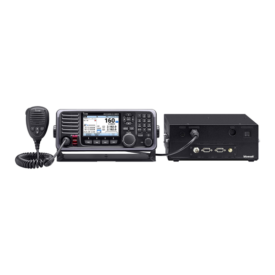
MF/HF MARINE TRANSCEIVER
|M803
This device complies with Part 15 of the FCC rules� Operation is
subject to the following two conditions: (1) This device may not cause
harmful interference, and (2) this device must accept any interference
received, including interference that may cause undesired operation�
Advertisement
Table of Contents

Related Manuals for Icom IC-M803


Summary of Contents for Icom IC-M803
- Page 1 INSTRUCTION MANUAL MF/HF MARINE TRANSCEIVER |M803 This device complies with Part 15 of the FCC rules� Operation is subject to the following two conditions: (1) This device may not cause harmful interference, and (2) this device must accept any interference received, including interference that may cause undesired operation�...
-
Page 2: Important
Thank you for choosing this Icom product� This product is designed and built with Icom’s state of the art technology and craftsmanship� With proper care, this product should provide you with years of trouble- free operation� IMPORTANT IN CASE OF EMERGENCY... -
Page 3: Radio Operation Warning
OP É RATEURS RADIO Icom requires the radio operator to meet the FCC Requirements for Radio Icom exige que l’opé rateur radio se conforme Frequency Exposure� An omnidirectional aux exigences de la FCC en matiè re antenna with gain not greater than 9 dBi d’exposition aux radiofré... -
Page 4: Fcc Information
MISE EN GARDE: out c angement ou mo ification transceiver, not expressly approved by Icom Inc�, could void your authority to operate this transceiver non expressé ment approuvé par Icom Inc�, peut annuler l autorisation e l utilisateur utiliser cet under FCC regulations�... -
Page 5: Percautions
PERCAUTIONS R DANGER HIGH RF VOLTAGE! NEVER touch CAUTION: DO NOT use non-Icom microphones� t er manu acturer s microp ones a e i erent pin an antenna while transmitting� This may result in an electrical shock or burn� assignments, and connection to the transceiver may damage the transceiver�... -
Page 6: Pré Cautions
ATTENTION : NE PAS utiliser de microphones autres une tempê te� que Icom� Les microphones des autres fabricants isposent a ectation e roc es i rentes et R AVERTISSEMENT ! NE J AMAIS brancher le raccordement au l’é... -
Page 7: Key Icon Description
You can use the following keys on the Menu screen� is cracked or broken, or the remote controller has been dropped� Contact your Icom distributor or your FUNCTION ACTION dealer for advice�... -
Page 8: Table Of Contents
D Distress Cancel call �������������������32 D AT-130/AT-120/AH-3 PREPARATION ......9 D Sending a Distress Relay �������������������������72 Entering the MMSI code ������������������9 D Non-Icom Tuner ������������������������72 Acknowledgment �����������������������34 D AT-140 MENU SCREEN ...... 10 Sending DSC calls (other) �������������35 D Sending an Individual call ���������35 ����������������������������������������72... -
Page 9: Operating Rules
OPERATING RULES NOTE: Before transmitting, monitor the channel you want to use to avoid interrupting communications already in progress� z CALL PROCEDURE z RADIO LICENSES Calls must e properl i entifie an t e time limit (1) SHIP RADIO STATION LICENSE must be respected�... -
Page 10: Panel Description
PANEL DESCRIPTION I Main unit front panel 1 SPEAKER J ACK [EXT-SP] (p. 69) 6 MODEM CONNECTOR [AF/MOD] (pp. 69, 79) Connects to the optional SP-24 or an external Connects to an e-mail modem, NBDP (Narrow speaker� Band Direct Printing) or FAX system through an RS-232C cable (D-sub 9-pin)�... -
Page 11: Main Unit Rear Panel
PANEL DESCRIPTION I Main unit rear panel 1 TUNER CONTROL SOCKET (pp. 70, 71, 78) 4 DSC ANTENNA CONNECTOR (p. 70, 71) Connects to a marine an antenna Connects to the control cable of the supplied t roug a or a SC recei er AT-140 �... -
Page 12: Remote Controller Front Panel
PANEL DESCRIPTION I Remote Controller front panel 2 3 4 2 3 FUNCTION DISPLAY (p. 7) SPEAKER MICROPHONE SOFTWARE KEYS (p. 5) CONNECTOR (pp. 68, 78) 1 DISTRESS KEY [DISTRESS] 8 VOLUME DIAL [VOL] o n or secon s to transmit a istress call z Rotate to adjust the speaker volume level�... -
Page 13: Optional
PANEL DESCRIPTION I Optional HM-214M I Software Keys Various often-used functions are assigned to the Software Keys for easy access� The function’s icons are displayed above the Software Keys, as shown MICROPHONE below� D Selecting a Software Key function to sli e t roug t e selecta le functions that are assigned to the Software Keys�... -
Page 14: D Functions
PANEL DESCRIPTION I Software key function D Functions You can use various Software Key functions that are assigned to the Software Keys, as described below� Compose Distress RF Gain Push to compose a Distress call� (pp� 29 ~ 34) Push to adjust the Radio Frequency (RF) gain level� (p�... -
Page 15: Function Display (Main Screen)
PANEL DESCRIPTION I Function display (Main screen) D Information area The 9 digit MMSI (Maritime Mobile Service Identity: Status area DSC self ID) code and the following indicators are Task area Information area displayed in the information area� Indicator Description Displayed when receiving a signal, or when the squelch is open�... -
Page 16: D Software Key Area
PANEL DESCRIPTION I Function display D Software Key area The Key function for each Software Key is displayed� See page 5 for details� D Position and Time area Position area The current position is displayed when valid GPS data is received, or when you manually enter your position� Indicator Description Displayed when a GPS receiver is not... -
Page 17: Preparation
PREPARATION I Entering the MMSI code 6� Enter your MMSI code again to confirm� The Maritime Mobile Service Identity (MMSI: DSC self Rotate ID) code consists of 9 digits� You can only enter the co e en turning t e transcei er or t e first time This initial code can be entered only once. -
Page 18: Menu Screen
MENU SCREEN o select an item rotate C GRP or pus The Menu screen is used to set items, select options, and so on for the transceiver’s functions� I Menu Construction The Menu screen is constructed in a tree structure� Rotate You can go to the next tree level by pushing [ENT], an go ac a le el... -
Page 19: Selecting The Item
I Selectin the item ollo t e proce ures escri e elo to select a Menu screen� ample urning t e oice S uelc unction oice S 1� Ra io Settings Voice SQL Rotate Push Rotate Push Select Rotate Push •... -
Page 20: Basic Operation
BASIC OPERATION I Selecting a channel or Group [ENT] [ENT] D Using the channel and group selector 1� Push [CH/GRP] to toggle between the Channel Keypad Select mode and the Group Select mode� keys • is displayed� 2� Rotate [CH/GRP] to select a channel or group� L When selecting the Group Select mode, the [CH/GRP] [CLR]... -
Page 21: Receiving And Transmitting
BASIC OPERATION I Receiving and transmitting D Receiving 1� Select a channel by rotating [CH/GRP], or pushing the Keypad keys� (p� 12) Keypad 2� When receiving a call, rotate [VOL] to adjust the keys audio output level� TIP: When a call is received: •... -
Page 22: Cw Operation
BASIC OPERATION I CW operation CW key connection The transceiver has the following CW keying features selectable in the Set mode, as described on page 67� z Full: Immediately returns to receive when you release the key� z Delay: Returns to receive after 0�5 seconds has passed after you stop keying�... -
Page 23: E-Mail Operation
BASIC OPERATION I e-mail operation The IC-M803 is ready for HF e-mail operation— up NOTE: to 160 e-mail frequency channels, and a connection • For e-mail operation, you MUST make a contract terminal for an e-mail modem are available� with an HF e-mail provider and purchase an Independent e-mail frequencies with operating mode e-mail modem from the provider, or your dealer�... -
Page 24: Other Functions And Operations
OTHER FUNCTIONS AND OPERATIONS I Backlight function I Scan The function display and keys can be backlit for better The transceiver has automatic channel and frequency visibility under low light conditions� scan capabilities (Scan function)� There are 3 types of You can set the Backlight mode to Day mode or Night scan functions�... -
Page 25: D Program
I Using the Voice Recorder D Program The Program scan searches the selected channel The transceiver has an automatic recording function it in t e re uenc range set t e Start re uenc that can record the last 120 seconds of the receiving setting an t e re uenc setting (p�... -
Page 26: Other Functions
I Other functions Emergency FREQ channel Squelch function Select t e istress oice re uenc en t is The Squelch function mutes unwanted signals such c annel is selecte t e oice re uenc o a SC as noise or unmodulated beat signals� This function call can be monitored without receiving or transmitting enables quiet standby�... - Page 27 Clarity Control function Automatic Gain Control OFF e utomatic Gain Control ( GC) unction pre ents With the Clarity Control function, you can slightly shift the receive frequency, without changing the operating distortion from strong signals and maintains a transmit re uenc to finel tune it en t e unction constant output level�...
-
Page 28: Frequency
I Setting a temporary operating frequency You can temporarily change the operating frequency of the selected channel� The frequency returns to the preset value after you select another channel, or turn t e transcei er 1� Select a channel that is programmed near the 5�... -
Page 29: Setting A User Channel, An Itu Simplex Channel, Or An E-Mail
I Setting a User channel, an ITU Simplex channel, or an e-mail channel Your dealer has already preset User channels, ITU 2� Enter an RX frequency, and then push � Simplex channels, and e-mail channels� ollo t e instructions as escri e Rotate you need to edit the channels�... -
Page 30: Assigning A Function
I Assigning a function I Setting a User channel, an ITU Simplex channel, or an e-mail channel ou can assign i erent So t are e unctions to a Step 4. Setting a channel name key between Soft Key 1 and Soft Key 20� (p� 5) You can set a channel name of up to 10 characters for each User channel, ITU Simplex channel, or You can also assign some Software Key functions to... -
Page 31: To [Vol]
D Assigning a Software Key function to D Assigning a Software Key function to [VOL] [P] on the HM-214H olume ial ssignment pen P e ssignment 1� 1� Configuration ssignment Configuration ssignment Volume Dial Assignment P Key Assignment 2� Select a place� 2�... -
Page 32: Dsc Operation
DSC OPERATION I DSC address ID 6� Enter a receive frequency, and then push � Rotate Entering an Individual or Group ID You can enter a total of 75 Individual IDs and 25 Group IDs, and assign names to them of up to 10 characters� 1�... -
Page 33: D Delete An Entered
DSC OPERATION D Delete an entered ID 11� Select “Name�” ample eleting an n i i ual Rotate 1� Open “Individual ID�” [MENU] > DSC Settings > Individual ID 2� Select t e S an t en pus � Push •... -
Page 34: Entering The Position Data And Time
DSC OPERATION I Entering the position data and time A Distress call should include the vessel’s position, 4� Enter the UTC time, and then push � date, and time� If no GPS data is received, manually • After is pushed, the entered position enter the position and Universal Time Coordinated data and time is set, and the DSC setting screen is C) time... -
Page 35: D Software Key Functions
DSC OPERATION I DSC Task mode (Single) e ollo ing unctions ma e ispla e epen ing After sending or receiving a DSC call, the transceiver enters the DSC Task mode� on the call type� If Single Task is enabled, the transceiver can hold up only 1 task�... -
Page 36: Dsc Task Mode (Multiple)
DSC OPERATION I DSC Task mode (Multiple) e ollo ing unctions ma e ispla e epen ing If Multiple Task is enabled, the transceiver can hold up to 7 tasks� You can make more than 2 DSC tasks on the call type� simultaneousl s itc ing et een t e tas s Function... -
Page 37: Sending Dsc Calls (Distress)
DSC OPERATION I Sending DSC calls (Distress) A Distress call should be sent if, in the opinion of 5� Push � the captain, the vessel or a person is in distress and requires immediate assistance� NEVER MAKE A DISTRESS CALL IF YOUR VESSEL OR A PERSON IS NOT IN AN EMERGENCY. -
Page 38: D Regular Call
DSC OPERATION I Sen ing SC calls ( istress) Step 3. Setting a communication frequency 1� Select “Attempt�” D Regular call Rotate Select the nature of the Distress call to include in the Regular Distress call� 1� Push � • The “COMPOSE DISTRESS” screen is displayed� Push L o ispla t e screen rom t e enu screen... -
Page 39: D Resending A Distress Call
DSC OPERATION 4� Push � 5� Push � o n P an t en e plain our situation o n P an t en e plain our situation 5� 6� ter ou a e inis e our e planation pus ter ou a e inis e our e planation pus 6�... -
Page 40: D Distress Cancel Call
DSC OPERATION I Sen ing SC calls ( istress) ter sen ing t e ollo ing screen is ispla e 3� Push � D Distress Cancel call If you have accidentally made a Distress call, or made an incorrect Distress call, send a Distress Cancel call to cancel t e call as soon as possi le ile aiting or an c no le gment... - Page 41 DSC OPERATION ter sen ing t e ollo ing screen is ispla e While waiting for Distress ACK 3� aiting or istress C is ispla e Push � 1� push � 4� Select a frequency to send a voice cancel message� L See pages or etails o t e So t are e Rotate...
-
Page 42: D Sending A Distress Relay
DSC OPERATION I Sen ing SC calls ( istress) 5� Push to send a Distress Relay c no le gment D Sending a Distress Relay ter sen ing t e ollo ing screen is ispla e 6� Acknowledgment ou can sen t e istress Rela c no le gment only after the Distress Relay call is received�... -
Page 43: Sending Dsc Calls (Other)
DSC OPERATION I Sending DSC calls (other) 5� Select a Call frequency, or “Manual Input�” Rotate D Sending an Individual call An Individual call enables you to send a DSC signal to onl a specific station Push You can communicate after receiving the c no le gment C (a le) L You can send an Individual call to a pre-entered Individual... -
Page 44: Acknowledgment
DSC OPERATION I Sen ing SC calls (ot er) D Sending an Individual Acknowledgment en ou a e recei e an n i i ual call (p D Sen ing an n i i ual call (continue ) sen an c no le gment to t e calling station en ou recei e an c no le gment le to 9�... -
Page 45: D Sending A Group Call
DSC OPERATION D Sending a Group call 4� Confirm the contents� A Group call enables you to send a DSC call to only a specific group Rotate L You can send a Group call to a pre-entered group address, or manually enter the address before sending� 1�... - Page 46 DSC OPERATION I Sen ing SC calls (ot er) D Sen ing a Group call (continue ) 6� Select “Call frequency�” 10� Push to send a Group call� • “Transmitting Group Call” is displayed, and then Rotate “Group Call” is displayed� Push 7�...
-
Page 47: D Sending A Geographical Area Call
DSC OPERATION D Sending a Geographical Area call When “Circle” is selected: ou can sen a Geograp ical rea call it in t e Sen a Geograp ical rea call en it is necessar to area covered by a set nautical mile radius from your send an urgent or safety message announcement to position�... - Page 48 DSC OPERATION I Sen ing SC calls (ot er) nter t e i t o t e Geograp ical rea call 4� area, and then push � D Sen ing a Geograp ical rea call (continue ) Rotate When “Quadrant” is selected: ou can sen a Geograp ical rea call it in t e s uare as s o n elo our essel s position is t e...
- Page 49 DSC OPERATION 11� Select a voice frequency, or “Manual Input�” Rotate Push en ou select anual nput in NOTE: this step, push the Keypad key to manually enter a voice frequency� 12� Push to send a Geographical Area call� • “Transmitting Geographical Call” is displayed, and then “Geographical Call”...
-
Page 50: D Sending A Test Call
DSC OPERATION D Sending a Test call 6� Select “Call frequency�” ou s oul a oi testing calls on t e e clusi e SC Rotate istress c annels an sa et calling c annels you cannot avoid testing on a Distress or safety channel, you should indicate that these are test calls�... -
Page 51: Acknowledgment
DSC OPERATION D Sending a Test call Acknowledgment en ou a e recei e a est call (p ), send an c no le gment to t e calling station is set to anual (p o t e ollo ing steps to sen an c no le gment ile a est call is eing recei e 1�... -
Page 52: Receiving Dsc Calls (Distress)
DSC OPERATION I Receiving DSC calls (Distress) The transceiver receives Distress calls, Distress c no le gments an istress Cancel calls en ou recei e a call an mergenc larm soun s continuousl lin s ile transcei er NOTE: Rotate has DSC call or an unread DSC message in the Received Call Log�... -
Page 53: Acknowledgment
DSC OPERATION D Receiving a Distress Acknowledgment D Receiving a Distress Cancel call When a Distress Acknowledgment is received: When a Distress Cancel call is received: • The emergency alarm sounds until you turn it OFF� • The emergency alarm sounds until you turn it OFF� •... -
Page 54: D Receiving A Distress Relay Call
DSC OPERATION I Recei ing SC calls ( istress) D Receiving a Distress Relay call When a Distress Relay call is received: D Recei ing a istress Cancel call (continue ) • The emergency alarm sounds until you turn it OFF� 3�... -
Page 55: D Receiving A Distress Relay
DSC OPERATION D Receiving a Distress Relay 3� Push , and then to return to the Main screen� Acknowledgment When a Distress Relay Acknowledgment is received: en ou pus TIP: in step 2, the • The emergency alarm sounds until you turn it OFF� count o n ill e pause •... -
Page 56: Receiving Dsc Calls (Other)
DSC OPERATION 3� Pus a e to select an c no le gment option I Receiving DSC calls (other) • The Call Contents screen is displayed D Receiving an Individual call NOTE: en t e n i i ual C is set to uto ( •... -
Page 57: Acknowledgment
DSC OPERATION D Receiving an Individual Acknowledgment When receiving “ACK (Able)”: When receiving “ACK (Unable)”: You can communicate on the frequency that you You cannot communicate further� specifie en sen ing t e call C ( na le) is recei e 1�... -
Page 58: D Receiving A Group Call
DSC OPERATION I Recei ing SC calls (ot er) D Receiving a Group call D Recei ing an n i i ual c no le gment (continue ) NOTE: To receive an Group call, push [D-SCAN] to enter t e SC atc mo e (p When receiving “ACK (New CH)”: You can communicate on the frequency that the called station proposed�... -
Page 59: D Receiving A Geographical Area
DSC OPERATION D Receiving a Geographical Area call When a Geographical Area call is received: • The emergency alarm sounds until you turn it OFF� • “Received Geographical” is displayed� Rotate 1� Push to turn OFF the alarm� • Monitor the Voice frequency that the calling station specifie L Rotate C GRP to confirm t e call contents ccept a ter... -
Page 60: D Receiving A Test Call
DSC OPERATION I Recei ing SC calls (ot er) D Receiving a Test call en t e est C is set to uto t e D Recei ing a Geograp ical rea call (continue ) NOTE: transcei er automaticall sen s an c no le gment 3�... -
Page 61: D Receiving A Test Acknowledgment
DSC OPERATION D Receiving a Test Acknowledgment When a Test Acknowledgment is received: • The alarm sounds until you turn it OFF� • “Received Test ACK” is displayed� 1� Push to turn OFF the alarm� 2� Push � Rotate L Rotate C GRP to confirm t e call contents L See pages or etails o t e So t are e functions in the DSC Task mode�... -
Page 62: Dsc Log
DSC OPERATION I DSC Log NOTE: is ispla e en t ere Rotate • On the Main screen, is an unread DSC message� lin s en a ne • On the Main screen, message is received� n t e ain screen no icon is ispla e •... -
Page 63: Dsc Settings
DSC OPERATION I DSC Settings 6� Enter a receive frequency, and then push � D Position nput (p Rotate D n i i ual D Group D DSC Frequency Push is set re uencies are selecta le en ou ant to send an Individual call, Group call, and Geographical Area call�... -
Page 64: D Scanning Receiver
DSC OPERATION D Scanning Receiver I DSC Settings You can turn the Scanning Receiver function ON or D SC re uenc (continue ) OFF on each Emergency Frequency� 11� Push to save the ID� When selecting “Distress frequency” • The entered name is displayed� NOTE: You cannot turn OFF the function on o t e remaining 4 frequencies�... -
Page 65: D Auto Ack
DSC OPERATION D Auto ACK The Auto ACK function automatically sends an c no le gment en an appropriate re uest is received� When selecting or editing “Routine frequency” 1� Open “Auto ACK�” 1� Open “Routine�” [MENU] > DSC Settings > Auto ACK [MENU] >... -
Page 66: D Ch Auto Switch
DSC OPERATION D Alarm Status I DSC Settings Sets t e alarm en recei ing eac t pe D CH Auto Switch of DSC call� regulation a ter recei ing a SC call t e transcei er automaticall s itc es t e operating c annel to t e Safety/Routine ispla e re uenc... - Page 67 DSC OPERATION 3� Select an option� Rotate Discrete Select et er or not to soun an alarm recei ing a lo er priorit SC call ile currentl receiving a higher priority call� 1� Open “Alarm Status�” Push [MENU] > DSC Settings > Alarm Status larm soun s •...
-
Page 68: D Self Check Test
DSC OPERATION I DSC Settings D Self Check Test The Self Check test sends DSC signals to the receiving AF circuit to compare the sending and receiving signals at the AF level� 1� Open “Self Check Test�” [MENU] > DSC Settings > Self Check Test 2�... -
Page 69: Menu Items
MENU ITEMS D Radio Settings I Menu items Item Reference The Menu screen is constructed in a tree structure� — p� 21 User CH (p�10) — MAX User CH p� 65 NOTE: See page 11 about how to select each Menu —... -
Page 70: Gps Information
MENU ITEMS z Night Mode Time I GPS Information [MENU] > Configuration ispla Displays the data received by the external GPS receiver� Night Mode Time Set the start time and end time of Night mode� Rotate Push I onfi uration D Key Beep D Displays Configuration... - Page 71 MENU ITEMS D Inactivity Timer For RT Related: Configuration Inactivity Timer Set t e nacti it timer to sec or between 1 and 10 min (in 1 minute steps)� The transceiver automatically returns to the Main screen if you push no key for the set period time for each mode�...
- Page 72 MENU ITEMS I Configuration D Remote z Interface D GPS (continued) Configuration Remote z External GPS Interface Configuration Select the interface format for the remote connector External GPS from NMEA or RS-232C� Select the data transfer speed to receive data from an e ternal GPS recei er rom 38400 bps�...
-
Page 73: Radio Settings
MENU ITEMS D Noise Reduction I Radio Settings [MENU] > Radio Settings > Noise Reduction D User CH (p. 21) Set t e oise Re uction le el to et een D e-mail CH (p. 21) OFF� D ITU Simplex CH (p. 21) D Max User CH [MENU] >... - Page 74 MENU ITEMS D IF Filter I Radio Settings [MENU] > Radio Settings > IF Filter D Scan (continued) z Program Scan FREQ Select the IF Filter passband width for the AFSK and S mo e operation rom le an arro [MENU] >...
-
Page 75: Radio Information
MENU ITEMS D Instant Replay z Shift Frequency z Function [MENU] > Radio Settings > FSK > Shift Frequency [MENU] > Radio Settings > Instant Replay > Function Set the FSK shift frequency for the FSK operation Turn the Instant Replay function ON or OFF� This function enables you to record the received au io ata an repla it •... -
Page 76: Connections And Installation
2� Rotate the connector clockwise until it is controller may lose its waterproof protection� completely tightened� • DO NOT use non-Icom microphones� Other manu acturer s microp ones a e i erent pin assignments, and connection to the remote controller may damage it�... -
Page 77: D Connecting The Remote Control
CONNECTIONS AND INSTALLATION D Connecting the remote control cable 1� Insert the remote control cable’s connector into the CAUTION: Be sure that the control cable’s main unit jack on the remote controller’s back panel� connector is screwed to the remote controller’s back 2�... -
Page 78: D Rear Panel Connections
(10 m, 32�8 ft, purchase separately) 12 V battery CAUTION: NOTE: Disconnect the battery from the IC-M803 • After connecting an antenna, tuner control cables, Main unit, or charge the battery while at anchor, external speaker, or GPS receiver, cover the otherwise the battery may become exhausted�... -
Page 79: Ground Connection
CONNECTIONS AND INSTALLATION I Ground connection The transceiver and antenna tuner must have an Best ground points adequate RF ground connection� Otherwise, the • External ground plate e cienc o t e transcei er an antenna tuner ma • Copper screen be reduced�... -
Page 80: Antenna
(p� 68) See page 78 for pin assignment� Control cable (user supplied) D Non-Icom Tuner D AT-140 Some non-Icom tuners may be used with the IC-M803� See page 70� Ask your dealer if you wish to connect one�... -
Page 81: Mounting
CONNECTIONS AND INSTALLATION I Mounting D Mounting location D Mounting the Main unit Select a location that provides easy access to the You can mount the Main unit using the mounting controller for navigation safety, has proper ventilation, bracket supplied with your transceiver� and is not subject to sea spray�... -
Page 82: Installation
CONNECTIONS AND INSTALLATION I MB-75 installation e optional us mount it is or mounting t e CAUTION: KEEP the transceiver and microphone remote controller to a at sur ace (less t an at least 1 meter (3�3 ft) away from your vessel’s thick), such as an instrument panel�... -
Page 83: Transceiver Dimensions
CONNECTIONS AND INSTALLATION I Transceiver dimensions 274 (10�8) 250 (9�8) 28 (1�1) 58 (2�3) 238 (9�4) 240 (9�4) Unit: mm (inch) -
Page 84: Fuse Replacement
CONNECTIONS AND INSTALLATION I Fuse replacement D Circuitry fuse 3� Replace the circuitry fuse, as shown in the diagram below� The transceiver has two kind of fuses to protect internal circuitry� CAUTION: Two fuses for the fuse holder on the DC power cable, •... -
Page 85: D Dc Power Cable Fuses
CONNECTIONS AND INSTALLATION D DC power cable fuses If a fuse blows, or the transceiver stops functioning, fin an repair t e cause o t e pro lem en replace the damaged fuse with a new adequately rated fuse� L Spare fuses are supplied with the transceiver� The fuses are installed in the DC power cable and in the inside circuitry, to protect the transceiver�... -
Page 86: Connector Information
CONNECTIONS AND INSTALLATION I Connector information Specification Pin Pin name Description CW and FSK keying input� Input level: –0�5 to 0�8 V Ground line for AF signal� – AF GND Input/Output pin� Ground level: –0�5 to 0�8 V SEND Ground this pin to transmit� Input current: Less than 20 mA nput impe ance... - Page 87 CONNECTIONS AND INSTALLATION Specification AF/MOD Pin Pin name Description nput impe ance ore t an Modulation input from an external terminal unit� Input level: Approximately MOD+ 0�77 V rms Coaxial ground for MOD+� – MOD– Ground for digital equipment� – utput impe ance ess t an AF detector output for an external...
-
Page 88: Specifications And Options
SPECIFICATIONS AND OPTIONS I Specifications D General D Transmitter • Frequency coverage: • Output power: 0�5 ~ 29�9999 MHz (Continuously) 1�6 ~ 27�5000 MHz 1�6 ~ 2�9999 MHz, 4�0 ~ 4�9999 MHz 150/100/60/20 W PEP (Selectable) 6�0 ~ 6�9999 MHz, 8�0 ~ 8�9999 MHz •... - Page 89 SPECIFICATIONS AND OPTIONS I Options D Antenna tuner • AT-130/AT-140 Matches the transceiver to a long wire antenna with little insertion loss� D Antenna • AH-710 Covers from 1�9 to 30 MHz band� Has an SO-239 connector� Easy to assemble (non- kink construction)�...
-
Page 90: Troubleshooting
TROUBLESHOOTING The transceiver does not turn ON. z Bad connection to the power supply� Check the connection between the transceiver and the power supply� (p� 71) z The fuse is blown� Repair the problem, and then replace the fuse� (pp� 76, 77) Little or no sound comes from the speaker. -
Page 91: Template
114 (4 95�4 (3... -
Page 93: Index
INDEX DSC Task mode Multiple ����������������������������������������������������������������� 28 Accessories �������������������������������������������������������������� 68 Single ������������������������������������������������������������������� 27 Alarm Status (DSC Settings) ������������������������������������ 58 Antenna �������������������������������������������������������������������� 72 AT-130/AT-120/AH-3 ������������������������������������������������� 72 AT-140 ���������������������������������������������������������������������� 70 e-mail Auto ACK (DSC Settings) ����������������������������������������� 57 Channel ���������������������������������������������������������������� 21 Automatic Gain Control OFF ������������������������������������ 19 Filter ���������������������������������������������������������������������... - Page 94 INDEX IF Filter (Radio Settings)������������������������������������������� 66 Radio Information ����������������������������������������������������� 67 Indicators �������������������������������������������������������������������� 7 Receiving ������������������������������������������������������������������ 13 Remote (Configuration) �������������������������������������������� 64 Individual Acknowledgment Receiving �������������������������������������������������������������� 49 Remote controller Sending ���������������������������������������������������������������� 36 Panel description ���������������������������������������������������� 4 Individual call RF Gain Level����������������������������������������������������������� 18 Receiving ��������������������������������������������������������������...
- Page 95 MEMO...
- Page 96 A7539H-1US-0a Printed in Japan 1-1-32 Kamiminami, Hirano-ku, Osaka 547-0003, Japan © 2019 Icom Inc� Nov� 2019...
Need help?
Do you have a question about the IC-M803 and is the answer not in the manual?
Questions and answers