Table of Contents
Advertisement
Quick Links
Advertisement
Table of Contents

Related Manuals for nifty Heightrider HR28 Series


Summary of Contents for nifty Heightrider HR28 Series
- Page 1 Heightrider Operating & Safety Instructions HR28 (SP85) SERIES Manufactured by: Niftylift Limited Chalkdell Drive Shenley Wood Milton Keynes MK5 6GF England www.niftylift.com e-mail: info@niftylift.com Tel: +44 (0)1908 223456 Fax: +44 (0)1908 312733 M50441/03...
-
Page 3: Table Of Contents
Height Rider/SP Series Operating & Safety Instructions Table of Contents Introduction and General Information FOREWORD ..................... 2 SCOPE ......................3 INTRODUCING THE HEIGHT RIDER SELF-PROPELLED (SP) SERIES ....3 GENERAL SPECIFICATION ................4 IDENTIFICATION (UK PLATE)................5 EC DECLARATION OF CONFORMITY (Typical) ..........7 Safety MANDATORY PRECAUTIONS ................ -
Page 4: Introduction And General Information
Height Rider/SP Series Operating & Safety Instructions Appendix A Error Codes ......................43 Introduction and General Information FOREWORD The purpose of these manuals is to provide the customer with appropriate safety operating and maintenance instructions essential for proper machine operation. All information in these manuals should be READ and fully UNDERSTOOD before any attempt is made to operate the machine. -
Page 5: Scope
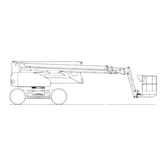
Niftylift Inc, 1525 S. Buncombe Road, Greer, SC 29651 USA Tel: +01 864 968 8881 Fax: +01 864 968 8836 Nifty Pty Ltd, 11 Kennington Drive, Tomago, NSW 2322, Australia Tel: +61 (0) 2 4964 9765 Fax: +61 (0) 2 4964 9714 Driven from the platform, the Niftylift Height Rider 28 (SP85) is an extremely versatile articulated boom platform of unique and simple design. -
Page 6: General Specification
Height Rider/SP Series Operating & Safety Instructions GENERAL SPECIFICATION FEATURE HR28 (SP85) MAXIMUM HEIGHT - WORKING 28.00 m 91 ft 10 in MAXIMUM HEIGHT - PLATFORM 26.00 m 85 ft 4 in MAXIMUM OUTREACH 18.90 m 62 ft 0 in MAXIMUM HEIGHT –... -
Page 7: Identification (Uk Plate)
Height Rider/SP Series Operating & Safety Instructions IDENTIFICATION (UK PLATE) This manufacturer’s plate is attached to the chassis on each machine at the time of manufacture on every Niftylift. Please ensure all sections have been stamped and are legible. English/USA – 04/15 Original instructions... - Page 8 Height Rider/SP Series Operating & Safety Instructions 1.5a IDENTIFICATION (USA PLATE) This manufacturer’s plate is attached to the chassis on each machine at the time of manufacture on every Niftylift. Please ensure all sections have been stamped and are legible. English/USA –...
-
Page 9: Ec Declaration Of Conformity (Typical)
Height Rider/SP Series Operating & Safety Instructions EC DECLARATION OF CONFORMITY (Typical) English/USA – 04/15 Original instructions... -
Page 10: Safety
Height Rider/SP Series Operating & Safety Instructions Safety MANDATORY PRECAUTIONS When operating your Niftylift, your safety is of utmost concern. In order to fully appreciate all aspects of the machine’s operation it should be ensured that each operator has READ and fully UNDERSTOOD the relevant manual covering machine use, maintenance and servicing. - Page 11 Height Rider/SP Series Operating & Safety Instructions 2.1.8 This machine contains several hazardous substances such as but not limited to: Battery acid, Hydraulic Fluid, Engine Coolant, Antifreeze, LPG, Diesel Fuel, Petrol, Engine Oil, Grease, and Gasoline. 2.1.9 Covers and canopies should remain closed when the machine is in operation. Only trained personnel should carry out maintenance on the machine, ensuring at all times they protect themselves from electrical, heat and mechanical hazards.
- Page 12 Height Rider/SP Series Operating & Safety Instructions 2.1.19 Always check that the area below and around the platform is clear of personnel and obstructions before lowering or slewing. Care should be taken when slewing out into areas where there may be passing traffic.
-
Page 13: Environmental Limitations
Height Rider/SP Series Operating & Safety Instructions 2.1.35 When the machine is not in use always stow the booms correctly. NEVER LEAVE THE KEYS IN THE MACHINE, if it is to be left for any period of time. Use wheel chocks if leaving on an incline. -
Page 14: Noise And Vibration
Height Rider/SP Series Operating & Safety Instructions NOISE AND VIBRATION The airborne noise emission on the Height Rider range of machines does not exceed 79dB(A), measured at a perpendicular distance of 4m, under equivalent continuous A-weighted sound pressure test conditions. This was based on a Diesel powered machine, working on high throttle, and under load. -
Page 15: Preparation And Inspection
Height Rider/SP Series Operating & Safety Instructions Preparation and Inspection UNPACKING Since the manufacturer has no direct control over the shipping or carriage of any Niftylift it is the responsibility of the dealer and/or owner and/or lessee to ensure the Niftylift has not been damaged in transit and a Pre-operational Report has been carried out by a qualified engineer before the aerial platform is put into service. -
Page 16: Pre-Operational Safety Check Schedules
Height Rider/SP Series Operating & Safety Instructions PRE-OPERATIONAL SAFETY CHECK SCHEDULES Before use each day and at the beginning of each shift the aerial platform shall be given a visual inspection and functional test including, but not limited to, the following: It is recommended that these be performed at regular intervals as indicated on each checklist. - Page 17 Height Rider/SP Series Operating & Safety Instructions 3.3.3 MONTHLY SAFETY CHECKS Check the engine oil level (if applicable). Check wheel nuts are secured (torque 292 ft lbs / 396 Nm). Check that the slew worm is secured and correctly in mesh. Clean and re-grease. Check the track rod linkage.
-
Page 18: Placard, Decals & Installation (Uk Spec)
Height Rider/SP Series Operating & Safety Instructions PLACARD, DECALS & INSTALLATION (UK SPEC) ITEM DESCRIPTION NUMBER Overload Warning P18848 “If Tilt Alarm Sounds” P14868 IPAF ‘Are you trained?’ P22055 Clunk Click P19961 “If E-Stop Disabled P14864 ‘Do not place objects on controls’ P21511 ‘Fitted with SiOPS’... - Page 19 Operating & Safety Instructions Auxiliary descent P25067 ‘Green Machine’ Large P22804 P17124 Noise Warning dB General crush hazard P14782 ‘Nifty HR28 Hybrid’ P24781 ‘Nifty HR28' P25690 Tier 4 / EU Stage IIIB P25407 Maintenance Free Batteries P27750 110V Charge point...
- Page 20 Height Rider/SP Series Operating & Safety Instructions English/USA – 04/15 Original instructions...
-
Page 21: Torque Requirements
Height Rider/SP Series Operating & Safety Instructions TORQUE REQUIREMENTS BOLT QUALITY/SIZE Tightening torque in lbs ft (Nm) Plated Unplated Grade 10.9 12.9 10.9 12.9 5 (7) 8 (10) 9 (12) 6 (8) 8 (11) 10 (13) 13 (17) 18 (25) 22 (29) 14 (19) 20 (27) -
Page 22: Operation
Height Rider/SP Series Operating & Safety Instructions Operation CONTROL CIRCUIT COMPONENTS 4.1.1 GROUND CONTROLS MASTER PROGRAMMEABLE LOGIC CONTROLLER (PLC): - Situated under the ground controls canopy, behind the Ground Controls Station is the Master PLC. The main purpose of the Master PLC is to process signals received from all areas of the control circuit on the machine and where appropriate output these to a series of smaller digital modules to operate the relevant machine functions. - Page 23 Height Rider/SP Series Operating & Safety Instructions SLEW SWITCH: - Mounted under the superstructure, this switch limits the drive speed to a preset low speed when the machine has been rotated from its stowed position. 4.1.2 PLATFORM PLATFORM PROGRAMMEABLE LOGIC CONTROLLER (PLC): - Situated in the platform is the Platform Control Station.
- Page 24 Height Rider/SP Series Operating & Safety Instructions BATTERY MANAGEMENT: - Battery condition is permanently monitored by the control circuit, such that when available power has decreased to 20% of full charge, the battery status circuit begins to "chop" the power to the hydraulic motors (If the machine is in Diesel mode at this point, it will automatically revert to a 'low power' state to protect the batteries).
-
Page 25: Ground Control Operation
Height Rider/SP Series Operating & Safety Instructions GROUND CONTROL OPERATION 4.2.1 GROUND CONTROL FUNCTIONS 1 Emergency Stop Push to Stop Operation Twist to Enable Operation 2 Green Power Button Push and hold for Power Release to Cease operation Indicates Safe Working Load limit or Maximum Tilt Angle exceeded. - Page 26 Height Rider/SP Series Operating & Safety Instructions Base Levers 1 Operates Platform Levelling Backward for Down Forward for Up 2 Operates the Flyboom Up for Up Down for Down 3 Operates Telescoping Up for Out Down for In 4 Operates the Link Booms Up for Up Down for Down 5 Operates the Upper Boom...
- Page 27 Height Rider/SP Series Operating & Safety Instructions DIESEL COLD ENGINE: - turn the Diesel Glow/Start selector to the Glow position (anti-clockwise). This engages the glow plug pre-heat system. Hold for 5-10 seconds then turn the key to the Start position (fully clockwise) and the engine will fire. However, there is a time delay dependant on fuel temperature (Refer to table below).
- Page 28 Height Rider/SP Series Operating & Safety Instructions EMERGENCY PROCEDURES Push in red emergency stop to shut down all functions. In the event that the controls fail or the operator becomes incapacitated the booms can be operated by using the auxiliary emergency pump which is located under the canopy adjacent to the base controls as follows: Operate appropriate control lever as required.
-
Page 29: Platform Control Operation
Height Rider/SP Series Operating & Safety Instructions PLATFORM CONTROL OPERATION 4.3.1 PLATFORM CONTROL FUNCTIONS Engine Glow/Start/Stop Anti-clockwise hold for Glow Clockwise to Start/Stop engine Speed Selector Booms Left - Speed I Centre - Speed II Right - Speed III Drive Tortoise Off-road Hare... - Page 30 Height Rider/SP Series Operating & Safety Instructions 4.3.2 CAGE DISPLAY UNIT Situated on the Cage Control Panel, this gauge provides a warning indication for a range of functions. For further information refer to Section 4.3.3 ‘Information Icons’ on Page 29. During machine operation the gauge displays current fuel or battery level, cage load status, current boom/drive speed setting and usage hours.
- Page 31 Height Rider/SP Series Operating & Safety Instructions 4.3.3 INFORMATION ICONS Safety Critical Safe Working Load exceeded:- The alarm sounds and the display alternates between the images shown here. The Maximum SWL (280kg/620lbs) has been exceeded. Immediately remove any unnecessary items from the platform in a safe manner to restore machine functions. Alternatively, the platform may have come into contact with a fixed object, see Section 5.3 for recovery procedure.
- Page 32 Height Rider/SP Series Operating & Safety Instructions Battery Power Machine is in operation using battery power. Diesel Engine Power Machine is in operation using engine power. Diesel Re-Gen (Hybrid mode) Machine is in operation using engine power and recharging the batteries. Oil Pressure/Water Temperature Low engine oil pressure or high water temperature.
- Page 33 Height Rider/SP Series Operating & Safety Instructions Diesel engine diagnostic page (HR28D only) To access this screen, press UP arrow. (Refer to Section 4.3.2) It also appears when starting the engine during crank delay (Refer to Section 4.2.2, Step 7). Water in fuel Refer to service manual for instructions on how to drain water from the diesel fuel filter.
- Page 34 Height Rider/SP Series Operating & Safety Instructions 4.3.4 OPERATION NEVER START THE NIFTYLIFT IF YOU SMELL PETROL (GASOLINE), LIQUID PROPANE OR DIESEL. THESE FUELS ARE FLAMMABLE. BEFORE OPERATING THE NIFTYLIFT ENSURE THAT EACH OPERATOR HAS READ AND FULLY UNDERSTOOD THE OPERATING MANUAL. FAILURE TO DO SO MAY RESULT IN DEATH OR SERIOUS INJURY.
- Page 35 Height Rider/SP Series Operating & Safety Instructions When not in use, return machine to stowed position. Note: Fully lower the Link booms first (Lever 4) followed by the Upper boom (Lever 5) for smooth operation. Turn the Base/Platform selector anti-clockwise to the Off position, remove key and chock wheels. ALWAYS ENSURE THE AERIAL PLATFORM IS ON A FIRM LEVEL SURFACE AND THE AREA IS FREE OF ANY OVERHEAD OBSTRUCTIONS.
-
Page 36: Driving Controls
Height Rider/SP Series Operating & Safety Instructions DRIVING CONTROLS DO NOT OPERATE THE NIFTYLIFT WHILST ELEVATED UNLESS ON A FIRM, LEVEL SURFACE FREE FROM ANY POSSIBLE OBSTRUCTIONS OR HAZARDS BOTH AT GROUND LEVEL AND OVERHEAD. Check proposed route for possible hazards, obstructions and personnel. Depress footswitch located on platform floor. -
Page 37: Cage Weigh System
Height Rider/SP Series Operating & Safety Instructions CAGE WEIGH SYSTEM 4.5.1 LOAD CELL VERSION The Niftylift HR28 is fitted with an electronic load cell. This load cell is a moment-independent, redundant design. This means that independent of the load position inside the machine cage, the actual load is measured and if pre-configured limit values are exceeded, warnings will be activated. -
Page 38: Batteries And Charging
Height Rider/SP Series Operating & Safety Instructions BATTERIES AND CHARGING Recharge batteries at the end of every working day or shift. (Note: To recharge batteries fully from 20% charged takes approx. 12 Hours, this consists of 8 hours bulk charging plus 4 hours equalisation. The recharging time can be reduced to approx 4- 6 hours by running the engine whilst charging). - Page 39 Height Rider/SP Series Operating & Safety Instructions During normal machine usage with the engine running, the batteries are on continuous recharge, except when the control system decides that additional electric power is required in order to maintain drive/function speed. The machine has two charging units (Master and Slave). Both units will activate initially, the Slave unit will switch off at approximately 80% capacity then the Master unit will complete the charging cycle.
- Page 40 Height Rider/SP Series Operating & Safety Instructions Attention should also be given to the use of extension cables as power leads. Excessive cable lengths from the supply point to the battery charger will result in significant voltage drop, leading to a reduction in the chargers efficiency.
-
Page 41: Transporting, Towing, Craneage, Storage And Setting To Work
Height Rider/SP Series Operating & Safety Instructions TRANSPORTING, TOWING, CRANEAGE, STORAGE, AND SETTING TO WORK 4.7.1 TRANSPORTING If a work platform is to be moved over a longer distance, whether the machine is trailer mounted, vehicle mounted, self propelled or tracked, the following procedure should be read before restraints are attached to the machine. - Page 42 Height Rider/SP Series Operating & Safety Instructions 4.7.2 TOWING If the Niftylift needs to be towed in case of an emergency, it will be necessary to chock the wheels before starting any of the following actions. GEARBOX DISENGAGEMENT In order to safely tow the HR28, the drive mechanism will need to be bypassed. The drive gearboxes located on the front and rear wheel hubs must be disengaged as follows;...
- Page 43 Height Rider/SP Series Operating & Safety Instructions 4.7.4 STORAGE If being stored for any length of time without use, then the machine should be thoroughly inspected for the following:- Grease all bearings /slides, worm drives, etc. If machine is to be left on an incline, chock wheels to prevent creep. If machine is to be left outside or in a hostile environment, cover with suitable weatherproof media to prevent deterioration.
-
Page 44: Emergency Controls
Height Rider/SP Series Operating & Safety Instructions Emergency Controls GENERAL CHECKING THE OPERATION OF THE EMERGENCY CONTROLS EVERY DAY AND/OR BEFORE EACH SHIFT IS AN ESSENTIAL PART OF THE OPERATOR'S DUTIES The operator and all ground personnel must be thoroughly familiar with the location and operation of the emergency controls. -
Page 45: Responsibilities
Height Rider/SP Series Operating & Safety Instructions Responsibilities CHANGES IN OWNERSHIP When a change of ownership of a Niftylift occurs, it shall be the responsibility of the seller to notify Niftylift directly of the unit, model and serial number and the name and address of the new owner within 60 days. -
Page 46: Inspection/Service/Pre-Hire Check List
Height Rider/SP Series Operating & Safety Instructions INSPECTION/SERVICE/PRE-HIRE CHECK LIST MACHINE SERIAL NO TOWING PASS FAIL Machine secured on trailer Straps correctly positioned and tightened Wheels chocked if necessary AXLES, WHEELS AND BRAKES Wheels are secure, tyre condition acceptable Wheel bearings O.K. Brake linkages and cables secure Brake shoe wear not excessive Machine climbs slope... - Page 47 Height Rider/SP Series Operating & Safety Instructions TILT ALARM PASS FAIL Booms raised on slope - drive disabled, siren tone constant Boom operation unaffected Booms lowered - drive restored INTERNAL (POWER PACK) Power pack and all components secure All cables and terminals secure All hose connections secure Hoses not kinked or fouled Charger/control box secure...
- Page 48 Height Rider/SP Series Operating & Safety Instructions Appendix A Code Fault Description Action Open circuit or short circuit of Check wiring to the base sounder Sounder Error the base sounder Check bulb is fitted Open circuit or short circuit of Base Green Button, Bulb Error Check wiring to the base green the base green button bulb...
- Page 49 Height Rider/SP Series Operating & Safety Instructions Code Fault Description Action Check wiring from the debug core of the Error of the corresponding programming port Debug Error digital input during PLC start up check - Reset power Check wiring from the 'base' side of the Error of the corresponding Key switch Base Switch key switch...
- Page 50 Height Rider/SP Series Operating & Safety Instructions Code Fault Description Action Check that there is around 60Ohms between CANH and CANL anywhere on the network The control system has detected an error in the Check there are no short circuits ERROR_CAN_SAFETY communication between the between CANH and CANL anywhere on...
- Page 51 Height Rider/SP Series Operating & Safety Instructions Code Fault Description Action Check paddle analogue voltages Paddle analogue outputs are Luffing Paddle Error Use another paddle to check inputs to not within spec of each other control system Check paddle analogue voltages Paddle analogue outputs are Slew Paddle Error Use another paddle to check inputs to...