nifty SP64 Series Operating/Safety Instructions Manual
Hide thumbs
Also See for SP64 Series:
- Operating/safety instructions manual (47 pages) ,
- Operating/safety instructions manual (45 pages)

Related Manuals for nifty SP64 Series


Summary of Contents for nifty SP64 Series
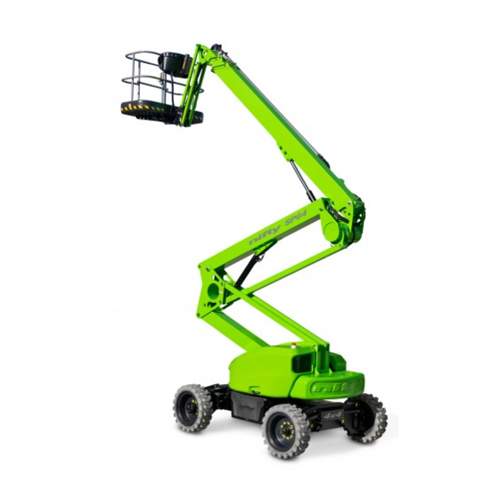
- Page 1 SP64 Operating & Safety Instructions MODEL SP64 SERIES (4x4) SP64 Niftylift Limited 1525 S.Buncombe Road Greer SC 29651 www.niftylift.com e-mail: niftyusa@niftylift.com Tel: 864-968-8881 Fax: 864-968-8836 M50408/02...
-
Page 3: Table Of Contents
SP Series Operating & Safety Instructions Table of Contents INTRODUCTION AND GENERAL INFORMATION PAGE Foreword Severity of Hazards Scope Introducing the Self Propelled (SP) Series General Specification Identification EC Declaration of Conformity (Typical) SAFETY Mandatory Precautions Environmental Limitations Noise & Vibration Test Report PREPARATION AND INSPECTION Unpacking... -
Page 4: Introduction And General Information Page
SP Series Operating & Safety Instructions Introduction and General Information FOREWORD The purpose of this manual is to provide the customer with safety, operating and maintenance instructions essential for proper Niftylift operation. This manual should be READ and fully UNDERSTOOD before any attempt is made to operate the Niftylift! Niftylift has no direct control over the Niftylift’s application and use, therefore conformance with good safety practices is the responsibility of the user and his operating personnel. -
Page 5: Scope
SP Series Operating & Safety Instructions SCOPE These operating instructions contain all the necessary information required to allow the safe operation of any Niftylift SP64, with a diesel (D) engine. For further technical information, circuit diagrams and specific instructions for all maintenance which may need to be carried out by specialist trained personnel, see the associated Workshop and Parts manual for your model of Niftylift Height Rider. -
Page 6: General Specification
SP Series Operating & Safety Instructions GENERAL SPECIFICATION FEATURE SP64 MAXIMUM HEIGHT - WORKING 67ft 9in MAXIMUM HEIGHT - PLATFORM 61ft 4in MAXIMUM OUTREACH 41ft 4in MAXIMUM HEIGHT – STOWED MAXIMUM WIDTH 7ft 5in MAXIMUM LENGTH – STOWED 16ft 5in PLATFORM CAPACITY - Europe 500lbs WHEELBASE... -
Page 7: Identification
SP Series Operating & Safety Instructions IDENTIFICATION (USA PLATE) This manufacturer’s plate is attached to Boom 1 on each Niftylift at the time of manufacture on every Niftylift. Please ensure all sections have been stamped and are legible. USA – 12/12... -
Page 8: Ec Declaration Of Conformity (Typical)
SP Series Operating & Safety Instructions EC DECLARATION OF CONFORMITY (Typical) USA – 12/12... -
Page 9: Safety
SP Series Operating & Safety Instructions Safety MANDATORY PRECAUTIONS When operating your Niftylift, your safety is of utmost concern. In order to fully appreciate all aspects of the Niftylifts operation it should be ensured that each operator has READ and fully UNDERSTOOD the relevant manual covering Niftylift use, maintenance and servicing. - Page 10 SP Series Operating & Safety Instructions 2.1.10 Never position any part of the Niftylift within 12ft of any electrical power line, conductor or similar not exceeding 66kV. (Minimum span 125m) Other distances for increased voltages and different spans are given in NZECP 34:1993. THIS NIFTYLIFT IS NOT INSULATED.
- Page 11 SP Series Operating & Safety Instructions 2.1.23 It shall be the responsibility of the user to determine the hazard classification of any particular atmosphere or location. Aerial platforms operated in hazardous locations shall be approved and suitable for the duty. (See ANSI/NFPA 505-1987 where applicable). 2.1.24 The operator shall immediately report to his supervisor any potentially hazardous location(s) (environment) which become evident during operation.
-
Page 12: Environmental Limitations
SP Series Operating & Safety Instructions ENVIRONMENTAL LIMITATIONS Unless specifically configured otherwise, the Niftylift will have a short operational time in extreme temperatures such as freezers and cold storage, due to reduced battery performance. For electrical cables and components, the temperature must be within the range -5°C to 60°C. The Niftylift is limited in high temperatures because of the cooling requirement for engines and hydraulic oil. -
Page 13: Test Report
SP Series Operating & Safety Instructions TEST REPORT All Niftylift models are subjected to a comprehensive ‘type test’ which duplicates all combinations of safe working load (SWL), overload, windage, inertia and pull force to assess the various safe stability criteria. Self propelled Niftylifts are also subjected to kerb and braking tests at the SWL to satisfy additional ‘worse case’... -
Page 14: Preparation And Inspection
SP Series Operating & Safety Instructions Preparation and Inspection UNPACKING Since the manufacturer has no direct control over the shipping or carriage of any Niftylift it is the responsibility of the dealer and/or owner and/or lessee to ensure the Niftylift has not been damaged in transit and a Pre-operational Report has been carried out by a qualified engineer before the aerial platform is put into service. -
Page 15: Pre-Operational Safety Check Schedules
SP Series Operating & Safety Instructions PRE-OPERATIONAL SAFETY CHECK SCHEDULES Before use each day and at the beginning of each shift the aerial platform shall be given a visual inspection and functional test including, but not limited to, the following: 3.3.1 DAILY SAFETY CHECKS Check that all labels (decals) are in place and legible. - Page 16 SP Series Operating & Safety Instructions 3.3.3 MONTHLY SAFETY CHECKS Check the engine oil level (if applicable). Check the wheel nuts (torque 110ft lbs / 150Nm). Check that the bolts holding the wheel motors to the chassis are secure. Check that the boom rotation gear worm is secured and correctly in mesh. Clean and re-grease. Inspect the engine fuel tank for damage or leaks.
- Page 17 SP Series Operating & Safety Instructions SPAIN, GREECE, TURKEY, CHINA, USA (MID WEST STATES), AUSTRALIA (TASMANIA) 9.5 years MALAYSIA, INDONESIA 8 years USA (SOUTH STATES), SOUTH AMERICA, AUSTRALIA (VICTORIA, NEW SOUTH WALES) 7.5 years USA (WEST STATES), SOUTH AFRICA, INDIA, PAKISTAN, IRAN, AUSTRALIA (WESTERN, 7 years SOUTH, QUEENSLAND) NORTH AFRICA, SAUDI, DUBIA, AUSTRALIA (NORTHERN TERRITORY)
-
Page 18: Placard, Decals And Installation
SP Series Operating & Safety Instructions PLACARD, DECALS & INSTALLATION (USA) ITEM DESCRIPTION NUMBER “Niftylift.com” P14390 Harness Point P14883 Head Protection P14921 Danger HR & TM’s P18672 “If E-Stop Disabled P21970 Hydraulic Oil P14415 SWL 500 lbs P17328 Manual Hand Pump P19605 Daily Safety Check List P14908... - Page 19 SP Series Operating & Safety Instructions USA – 12/12...
-
Page 20: Torque Requirements
SP Series Operating & Safety Instructions TORQUE REQUIREMENTS SCREW QUALITY/SIZE Tightening torque in ft lbs (Nm) Grade 10.9 (10) (14) (25) (35) M 10 (49) (69) M 12 (86) (120) M 14 (135) (190) M 16 (210) (295) M 18 (290) (405) WHEEL NUTS... -
Page 21: Operation
SP Series Operating & Safety Instructions Operation CONTROL CIRCUIT COMPONENTS 4.1.1 MAIN CONTROL BOARD: - Situated under the left-hand superstructure cover, the encapsulated control board comprises a PCB (printed circuit board) design which incorporates all of the relays to control the Niftylift operation. - Page 22 SP Series Operating & Safety Instructions 4.1.8 BATTERY MANAGEMENT (ELECTRIC/BI-ENERGY MODELS ONLY): - Battery condition is permanently monitored by the control circuit, such that when available power has decreased to 80% of full charge, the battery status circuit begins to "chop" the power to the hydraulic power packs. This function causes the drive system to alternately stop &...
-
Page 23: Ground Control Operation
SP Series Operating & Safety Instructions GROUND CONTROL OPERATION 4.2.1 GROUND CONTROL FUNCTIONS (Base Control Panel) 1 Emergency Stop Push to Stop Niftylift Turn clockwise to Release 2 Diesel Glow/Start Selector Turn Clockwise – Glow, Off and Start posistions 3 Basket Overload Indicator See Section 4.5 4 Base/Platform Selector Up for Basket... - Page 24 SP Series Operating & Safety Instructions 4.2.2 OPERATION ALWAYS ALLOW THE ENGINE TO WARM UP BEFORE OPERATING. ALL MODELS Ensure all red emergency stops are out. Turn Base/Basket selector at ground control station to Ground (Clockwise). DIESEL ENGINE COLD ENGINE: - turn the Diesel Glow/Start selector to the Glow position (anti-clockwise). This engages the glow plug pre-heat system.
-
Page 25: Basket Control Operation
SP Series Operating & Safety Instructions PLATFORM CONTROL OPERATION 4.3.1 PLATFORM CONTROL FUNCTIONS (Basket Control Panel) 1 Emergency Stop Push to Stop Niftylift Turn clockwise to Release 2 Horn Push to sound 3 Battery Charge Indicator 4 Basket Overload Indicators See Section 4.5 5 Diesel Glow/Start Anti-clockwise to Glow Engine, Clockwise to Start Engine... - Page 26 SP Series Operating & Safety Instructions 4.3.2 OPERATION NEVER START THE NIFTYLIFT IF YOU SMELL GASOLINE, LIQUID PROPANE OR DIESEL. THESE FUELS ARE FLAMMABLE. BEFORE OPERATING THE NIFTYLIFT ENSURE THAT EACH OPERATOR HAS READ AND FULLY UNDERSTOOD THE OPERATING MANUAL. FAILURE TO DO SO MAY RESULT IN DEATH OR SERIOUS INJURY.
- Page 27 SP Series Operating & Safety Instructions 4.3.3 SiOPS - LOAD SENSING CONSOLE (If fitted) WHEN OPERATING THIS NIFTYLIFT THE USER MUST BE AWARE OF ANY OVERHEAD OBSTRUCTIONS. This Niftylift incorporates a load sensing basket console that senses if the operator has been pushed or has fallen against the console.
-
Page 28: Driving Controls
Under no circumstances should any SP64 series Niftylift be driven on slopes exceeding the gradeability in the general specification ALL NIFTYLIFTS ARE FITTED WITH A TILT ALARM - PRE-SET IN THE FACTORY. -
Page 29: Basket Weigh System (If Fitted)
SP Series Operating & Safety Instructions BASKET WEIGH SYSTEM 4.5.1 LOAD CELL VERSION The Niftylift SP64 is fitted with an electronic load cell. This load cell is a moment-independent, redundant design. This means that independent of the load position inside the basket of the Niftylift, the actual load is measured and if pre-configured limit values are exceeded, warnings will be activated. -
Page 30: Transporting, Craneage, Storage And Setting To Work
SP Series Operating & Safety Instructions TRANSPORTING, CRANEAGE, STORAGE AND SETTING TO WORK 4.6.1 TRANSPORTING If a Niftylift is to be moved over a longer distance, whether the Niftylift is trailer mounted, vehicle mounted, self propelled or tracked, the following procedure should be read before restraints are attached to the Niftylift. - Page 31 SP Series Operating & Safety Instructions 4.6.2 CRANEAGE Observe all of the limitations relating to straps and chains stated above under ‘Transporting’. (4.6.1) When utilising the designated lifting points never apply a ‘snatch’ load, i.e. lift slowly to take up the load before raising.
- Page 32 SP Series Operating & Safety Instructions station with no load in the basket. Take care not to become trapped between the moving basket and a fixed object, and ensure those around you are clear of the moving basket. When the system has been charged in both directions, the basket levelling function should be restored.
-
Page 33: Emergency Controls
SP Series Operating & Safety Instructions Emergency Controls GENERAL CHECKING THE OPERATION OF THE EMERGENCY CONTROLS EVERY DAY AND/OR BEFORE EACH SHIFT IS AN ESSENTIAL PART OF THE OPERATOR'S DUTIES The operator and all ground personnel must be thoroughly familiar with the location and operation of the EMERGENCY CONTROLS. -
Page 34: Boom Controls
SP Series Operating & Safety Instructions BOOM CONTROLS On opening the canopy cover, the two hand pump handles are revealed. The black handle with a red handgrip fits the Boom hand pump. Remove the handle and fit this to the appropriate pump. When the handle is actuated, hydraulic flow is generated and will be supplied directly to the ground control valve block. -
Page 35: Towing
SP Series Operating & Safety Instructions TOWING If the Niftylift needs to be towed in case of an emergency, it will be necessary to chock the wheels before commencing gearbox disengagement. 5.5.1 IDENTIFYING GEARBOX TYPE In order to safely tow the SP64, the drive mechanism will need to be bypassed. Identify the type of gearbox fitted to the machine then refer to the relevant procedure for disengagement of the gearboxes. -
Page 36: Incident Notification
SP Series Operating & Safety Instructions 5.5.3 GEARBOX DISENGAGEMENT (TYPE 2) The drive gearboxes located on the front and rear wheel hubs must be disengaged as follows; Remove both retaining bolts that secure the cover disc to the centre of the wheel hub. Partially screw one of the retaining bolts into the end of the central disengage pin and pull the pin out fully, ensuring the recess on the pin is visible. -
Page 37: Inspection/ Service Check List
SP Series Operating & Safety Instructions Inspection/Service/Pre-Hire Check list NIFTYLIFT SERIAL NO TOWING PASS FAIL Niftylift secured on trailer Straps correctly positioned and tightened Wheels chocked if necessary AXLES, WHEELS AND BRAKES Wheels are secure, tire condition acceptable Wheel bearings O.K. Brake linkages and cables secure Brake shoe wear not excessive Niftylift climbs slope... - Page 38 SP Series Operating & Safety Instructions TILT ALARM PASS FAIL Booms raised on slope - drive disabled, siren tone constant Boom operation unaffected Booms lowered - drive restored INTERNAL (POWER PACK) Power pack and all components secure All cables and terminals secure All hose connections secure Hoses not kinked or fouled Charger/control box secure...
Need help?
Do you have a question about the SP64 Series and is the answer not in the manual?
Questions and answers