Table of Contents
Advertisement
Quick Links
Advertisement
Table of Contents

Related Manuals for nifty Heightrider SP HYBRID Series


Summary of Contents for nifty Heightrider SP HYBRID Series
- Page 1 Heightrider Operating & Safety Instructions HR15/17 HYBRID SERIES Manufactured by: Niftylift Limited Fingle Drive Stonebridge Milton Keynes MK13 0ER England www.niftylift.com e-mail: info@niftylift.com Tel: +44 (0)1908 223456 Fax: +44 (0)1908 312733 M50381/04...
-
Page 3: Table Of Contents
Height Rider/SP Series Operating & Safety Instructions Table of Contents Introduction and General Information FOREWORD ..................... 2 SCOPE ......................3 INTRODUCING THE HEIGHT RIDER SELF-PROPELLED (SP) SERIES ....3 GENERAL SPECIFICATION ................4 IDENTIFICATION (UK PLATE)................5 EC DECLARATION OF CONFORMITY (Typical) ..........7 Safety MANDATORY PRECAUTIONS ................ -
Page 4: Introduction And General Information
Height Rider/SP Series Operating & Safety Instructions Appendix A Error Codes ......................45 Introduction and General Information FOREWORD The purpose of these manuals is to provide the customer with appropriate safety operating and maintenance instructions essential for proper machine operation. All information in these manuals should be READ and fully UNDERSTOOD before any attempt is made to operate the machine. -
Page 5: Scope
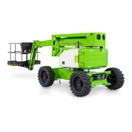
Niftylift Inc, 32 Concourse Way, Greer, SC 29651 USA Tel: +01 864 968 8881 Fax: +01 864 968 8836 Nifty Pty Ltd, 265 King Street, Newcastle, NSW 2300, Australia Tel: +61 (0) 2 4929 6700Fax: +61 (0) 2 4925 2570 Driven from the platform, the Niftylift Height Rider 15/17 (SP45/50) Hybrid is an extremely versatile articulated boom platform of unique and simple design. -
Page 6: General Specification
Height Rider/SP Series Operating & Safety Instructions GENERAL SPECIFICATION FEATURE HR15 HYBRID 4x4 HR17 HYBRID 4x4 MAXIMUM HEIGHT - WORKING 15.50m 17.00m 50ft 10in 55 ft 10 in MAXIMUM HEIGHT - PLATFORM 13.50 m 15.00m 44ft 3in 49 ft 3in MAXIMUM OUTREACH 9.20 m 30 ft 3in... -
Page 7: Identification (Uk Plate)
Height Rider/SP Series Operating & Safety Instructions IDENTIFICATION (UK PLATE) This manufacturer’s plate is attached to the chassis on each machine at the time of manufacture on every Niftylift. Please ensure all sections have been stamped and are legible. English/USA – 11/13 Original instructions... - Page 8 Height Rider/SP Series Operating & Safety Instructions 1.5a IDENTIFICATION (USA PLATE) This manufacturer’s plate is attached to the chassis on each machine at the time of manufacture on every Niftylift. Please ensure all sections have been stamped and are legible. English/USA –...
-
Page 9: Ec Declaration Of Conformity (Typical)
Height Rider/SP Series Operating & Safety Instructions EC DECLARATION OF CONFORMITY (Typical) English/USA – 11/13 Original instructions... -
Page 10: Safety
Height Rider/SP Series Operating & Safety Instructions Safety MANDATORY PRECAUTIONS When operating your Niftylift, your safety is of utmost concern. In order to fully appreciate all aspects of the machines operation it should be ensured that each operator has READ and fully UNDERSTOOD the relevant manual covering machine use, maintenance and servicing. - Page 11 Height Rider/SP Series Operating & Safety Instructions 2.1.8 This machine contains several hazardous substances such as but not limited to: Battery acid, Hydraulic Fluid, Engine Coolant, Antifreeze, LPG, Diesel Fuel, Petrol, Engine Oil, Grease, Gasoline. 2.1.9 Covers and canopies should remain closed when the machine is in operation. Only trained personnel should carry out maintenance on the machine, ensuring at all times they protect themselves from electrical, heat and mechanical hazards.
- Page 12 Height Rider/SP Series Operating & Safety Instructions 2.1.23 Under all travel conditions the operator shall limit travel speed according to conditions of ground surface, congestion, visibility, slope, location of personnel and other factors causing hazards of collision or injury to personnel. 2.1.24 The aerial platform shall not be driven on grades, side slopes or ramps exceeding those for which the aerial platform is rated by the manufacturer.
-
Page 13: Environmental Limitations
Height Rider/SP Series Operating & Safety Instructions 2.1.38 NEVER START THE NIFTYLIFT IF YOU SMELL PETROL (GASOLINE), LIQUID PROPANE OR DIESEL FUEL. THESE FUELS ARE HIGHLY FLAMMABLE 2.1.39 The operator shall implement means provided to protect against use by unauthorised persons. 2.1.40 Never remove anything that may affect the stability of the machine such as, but not limited to, batteries, covers, engines, tyres or ballast. -
Page 14: Test Report
Height Rider/SP Series Operating & Safety Instructions TEST REPORT All Niftylift machine models are subjected to a comprehensive ‘type test’ which duplicates all combinations of safe working load (SWL), overload, windage, inertia and pull force to assess the various safe stability criteria. Self propelled machines are also subjected to kerb and braking tests at the SWL to satisfy additional ‘worse case’... -
Page 15: Preparation And Inspection
Height Rider/SP Series Operating & Safety Instructions Preparation and Inspection UNPACKING Since the manufacturer has no direct control over the shipping or carriage of any Niftylift it is the responsibility of the dealer and/or owner and/or lessee to ensure the Niftylift has not been damaged in transit and a Pre-operational Report has been carried out by a qualified engineer before the aerial platform is put into service. -
Page 16: Pre-Operational Safety Check Schedules
Height Rider/SP Series Operating & Safety Instructions PRE-OPERATIONAL SAFETY CHECK SCHEDULES Before use each day and at the beginning of each shift the aerial platform shall be given a visual inspection and functional test including, but not limited to, the following: It is recommended that these be performed at regular intervals as indicated on each checklist. - Page 17 Height Rider/SP Series Operating & Safety Instructions 3.3.3 MONTHLY SAFETY CHECKS Check the engine oil level (if applicable). Check wheel nuts are secured (torque 110ft lbs / 150Nm). Check that the slew worm is secured and correctly in mesh. Clean and re-grease. Check the track rod linkage.
- Page 18 Height Rider/SP Series Operating & Safety Instructions USA (SOUTH STATES), SOUTH AMERICA, AUSTRALIA (VICTORIA, NEW SOUTH WALES) 7.5 years USA (WEST STATES), SOUTH AFRICA, INDIA, PAKISTAN, IRAN, AUSTRALIA (WESTERN, 7 years SOUTH, QUEENSLAND) NORTH AFRICA, SAUDI, DUBAI, AUSTRALIA (NORTHERN TERRITORY) 6 years Note: The date of manufacture of the toughcage floor is located on its underside.
-
Page 19: Placard, Decals & Installation (Uk Spec)
Height Rider/SP Series Operating & Safety Instructions PLACARD, DECALS & INSTALLATION (UK SPEC) ITEM DESCRIPTION NUMBER Serial Plate P15383 Point Loading P22980 Travel Direction P14784 No Step P14785 Charger Socket 240V P26425 P14697 ‘Green machine’ P22804 Noise Warning 85dB P17124 Charger Socket 110V P26424 General crush hazard... - Page 20 Height Rider/SP Series Operating & Safety Instructions Emergency controls location P21700 Pressurised tank P16365 Battery Drain P19850 Hydraulic Levers – Base P25066 Tie Down Points P14958 ‘Do not place objects on controls’ P21511 Manual Descent HR17/SP50 P23035 P23305 / E10001_002 P23556 P23305 / E10002_002 P23557...
- Page 21 Height Rider/SP Series Operating & Safety Instructions English/USA – 11/13 Original instructions...
-
Page 22: Torque Requirements
Height Rider/SP Series Operating & Safety Instructions TORQUE REQUIREMENTS SCREW QUALITY/SIZE Tightening torque in ft lbs (Nm) Grade 10.9 (10) (14) (25) (35) M 10 (49) (69) M 12 (86) (120) M 14 (135) (190) M 16 (210) (295) M 18 (290) (405) WHEEL NUTS... -
Page 23: Operation
Height Rider/SP Series Operating & Safety Instructions Operation CONTROL CIRCUIT COMPONENTS 4.1.1 GROUND CONTROLS MASTER PROGRAMMEABLE LOGIC CONTROLLER (PLC): - Situated under the ground controls canopy, behind the Ground Controls Station is the Master PLC. The main purpose of the Master PLC is to process signals received from all areas of the control circuit on the machine and where appropriate output these to a series of smaller digital modules to operate the relevant machine functions. - Page 24 Height Rider/SP Series Operating & Safety Instructions 4.1.2 PLATFORM PLATFORM PROGRAMMEABLE LOGIC CONTROLLER (PLC): - Situated in the platform is the Platform Control Station. Behind the platform control panel is the Platform PLC. The purpose of the Platform PLC is to interpret signals received from the Platform Control Station and convert them to a digital signal, which is then output to the Master PLC for processing.
- Page 25 Height Rider/SP Series Operating & Safety Instructions Note; During normal machine usage with the engine running, the batteries are on continuous recharge The exception to this is when the control system decides that additional electric power is required in order to maintain drive/function speed. If the operator is using electric power only and a low battery warning has activated, it is advisable to start the engine, enabling continued use of the machine, whilst at the same time recharging the batteries.
-
Page 26: Ground Control Operation
Height Rider/SP Series Operating & Safety Instructions GROUND CONTROL OPERATION 4.2.1 GROUND CONTROL FUNCTIONS To operate any control panel function; Push and hold Green Power button, Press and Hold required function to activate, then release to deactivate. (Ground Control Panel) 1 Emergency Stop Push to Stop Operation Twist to Enable Operation... - Page 27 Height Rider/SP Series Operating & Safety Instructions Base Levers 1 Operates Platform Levelling Up for Backward ** Down for Forward ** 2 Operates the Flyboom Up for Up Down for Down 3 Operates Telescoping Up for Out Down for In 4 Operates the Link Booms Up for Up Down for Down...
- Page 28 Height Rider/SP Series Operating & Safety Instructions To return control to the platform, turn base control key-switch to the Platform position (fully clockwise). When not in use return machine to stowed position, turn the base control key-switch anti- clockwise to the OFF position, remove key and chock wheels. EMERGENCY PROCEDURES Push in red emergency stop to shut down all functions.
-
Page 29: Platform Control Operation
Height Rider/SP Series Operating & Safety Instructions PLATFORM CONTROL OPERATION 4.3.1 PLATFORM CONTROL FUNCTIONS (Platform Control Station) Engine Glow/Start/Stop Anti-clockwise hold for Glow Clockwise to Start/Stop engine Variable Speed Control Anti-clockwise to decrease Clockwise to increase speed Terrain Selector Anti-clockwise for High Gear Clockwise for Low Gear (level ground) (gradient) - Page 30 Height Rider/SP Series Operating & Safety Instructions 4.3.2 MULTI-FUNCTION DIGITAL GAUGE Situated on the Cage Control Panel, this gauge provides a warning indication for a range of functions. The warning icons on the right hand side indicate a safety critical situation where immediate action is required;...
- Page 31 Height Rider/SP Series Operating & Safety Instructions 4.3.3 WARNING ICONS Advisory High Speed Drive Available : Machine can be driven at its maximum speed if ground and evironmental conditions are suitable and it is safe to proceed. High Water Temperature : Check engine coolant level. Caution, the cooling system is pressurised, so allow engine to cool sufficiently before removing filler cap.
- Page 32 Height Rider/SP Series Operating & Safety Instructions 4.3.4 OPERATION NEVER START THE NIFTYLIFT IF YOU SMELL PETROL (GASOLINE), LIQUID PROPANE OR DIESEL. THESE FUELS ARE FLAMMABLE. BEFORE OPERATING THE NIFTYLIFT ENSURE THAT EACH OPERATOR HAS READ AND FULLY UNDERSTOOD THE OPERATING MANUAL. FAILURE TO DO SO MAY RESULT IN DEATH OR SERIOUS INJURY.
- Page 33 Height Rider/SP Series Operating & Safety Instructions 4.3.5 SiOPS - LOAD SENSING CONSOLE (If fitted) WHEN OPERATING THIS MACHINE THE USER MUST BE AWARE OF ANY OVERHEAD OBSTRUCTIONS. This machine incorporates a load sensing cage console that senses if the operator has been pushed or has fallen against the console.
-
Page 34: Driving Controls
Height Rider/SP Series Operating & Safety Instructions DRIVING CONTROLS DO NOT OPERATE THE NIFTYLIFT WHILST ELEVATED UNLESS ON A FIRM, LEVEL SURFACE FREE FROM ANY POSSIBLE OBSTRUCTIONS OR HAZARDS BOTH AT GROUND LEVEL AND OVERHEAD. Check proposed route for possible hazards, obstructions and personnel. Depress footswitch located on platform floor. -
Page 35: Cage Weigh System
Height Rider/SP Series Operating & Safety Instructions CAGE WEIGH SYSTEM 4.5.1 LOAD CELL VERSION The Niftylift HR15/17 is fitted with an electronic load cell. This load cell is a moment-independent, redundant design. This means that independent of the load position inside the machine cage, the actual load is measured and if pre-configured limit values are exceeded, warnings will be activated. -
Page 36: Batteries And Charging
Height Rider/SP Series Operating & Safety Instructions BATTERIES AND CHARGING BATTERIES MUST BE RECHARGED IN A WELL-VENTILATED AREA FREE OF FLAME, SPARKS OR OTHER HAZARDS THAT MAY CAUSE EXPLOSION. HIGHLY EXPLOSIVE HYDROGEN GAS IS PRODUCED DURING THE CHARGING PROCESS. Recharge batteries at the end of every working day or shift. (Note: To recharge batteries fully from 20% takes approx. - Page 37 Height Rider/SP Series Operating & Safety Instructions During normal machine usage with the engine running, the batteries are on continuous recharge, except when the control system decides that additional electric power is required in order to maintain drive/function speed. Should the operator ignore the onset of the battery discharge warning the "shut down" of the motors will continue, until the machine is rendered in-operative.
- Page 38 Height Rider/SP Series Operating & Safety Instructions The charger requires a minimum battery voltage of 1.5 volts per battery (overall for two batteries 3 volts, for 4 batteries 6 volts for 8 batteries 12 volts and 18V for 72V). If the voltage is below these values then the charger will not function (Charger will not detect batteries to begin charge.) If the batteries have fallen to such a poor state they will have to be removed from the machine and charged individually with an independent charger until the optimum voltage has been reached.
-
Page 39: Transporting, Towing, Craneage, Storage And Setting To Work
Height Rider/SP Series Operating & Safety Instructions TRANSPORTING, TOWING, CRANEAGE, STORAGE AND SETTING TO WORK 4.7.1 TRANSPORTING If a work platform is to be moved over a longer distance, whether the machine is trailer mounted, vehicle mounted, self propelled or tracked, the following procedure should be read before restraints are attached to the machine. - Page 40 Height Rider/SP Series Operating & Safety Instructions 4.7.2 TOWING If the Niftylift needs to be towed in case of an emergency, it will be necessary to chock the wheels before starting any of the following actions. IDENTIFYING GEARBOX TYPE In order to safely tow the HR15/17, the drive mechanism will need to be bypassed. Identify the type of gearbox fitted to the machine then refer to the relevant procedure for disengagement of the gearboxes.
- Page 41 Height Rider/SP Series Operating & Safety Instructions GEARBOX DISENGAGEMENT (TYPE 2) The drive gearboxes located on the front and rear wheel hubs must be disengaged as follows; Remove both retaining bolts that secure the cover disc to the centre of the wheel hub. Partially screw one of the retaining bolts into the end of the central disengage pin and pull the pin out fully, ensuring the recess on the pin is visible.
- Page 42 Height Rider/SP Series Operating & Safety Instructions 4.7.4 STORAGE If being stored for any length of time without use, then the machine should be thoroughly inspected for the following:- Grease all bearings /slides, worm drives, etc. If machine is to be left on an incline, chock wheels to prevent creep. If machine is to be left outside or in a hostile environment, cover with suitable weatherproof media to prevent deterioration.
-
Page 43: Emergency Controls
Height Rider/SP Series Operating & Safety Instructions Emergency Controls GENERAL CHECKING THE OPERATION OF THE EMERGENCY CONTROLS EVERY DAY AND/OR BEFORE EACH SHIFT IS AN ESSENTIAL PART OF THE OPERATOR'S DUTIES The operator and all ground personnel must be thoroughly familiar with the location and operation of the emergency controls. -
Page 44: Responsibilities
Height Rider/SP Series Operating & Safety Instructions Responsibilities CHANGES IN OWNERSHIP When a change of ownership of a Niftylift occurs, it shall be the responsibility of the seller to notify Niftylift directly of the unit, model and serial number and the name and address of the new owner within 60 days. -
Page 45: Inspection/Service/Pre-Hire Check List
Height Rider/SP Series Operating & Safety Instructions INSPECTION/SERVICE/PRE-HIRE CHECK LIST MACHINE SERIAL NO TOWING PASS FAIL Machine secured on trailer Straps correctly positioned and tightened Wheels chocked if necessary AXLES, WHEELS AND BRAKES Wheels are secure, tyre condition acceptable Wheel bearings O.K. Brake linkages and cables secure Brake shoe wear not excessive Machine climbs slope... - Page 46 Height Rider/SP Series Operating & Safety Instructions TILT ALARM PASS FAIL Booms raised on slope - drive disabled, siren tone constant Boom operation unaffected Booms lowered - drive restored INTERNAL (POWER PACK) Power pack and all components secure All cables and terminals secure All hose connections secure Hoses not kinked or fouled Charger/control box secure...
- Page 47 Height Rider/SP Series Operating & Safety Instructions Appendix A Code Fault Description Action Open circuit or short circuit of Check wiring to the base sounder Sounder Error the base sounder Check bulb is fitted Open circuit or short circuit of Base Green Button, Bulb Error Check wiring to the base green the base green button bulb...
- Page 48 Height Rider/SP Series Operating & Safety Instructions Code Fault Description Action Check wiring from the debug core of the Error of the corresponding programming port Debug Error digital input during PLC start up check - Reset power Check wiring from the 'base' side of the Error of the corresponding Key switch Base Switch key switch...
- Page 49 Height Rider/SP Series Operating & Safety Instructions Code Fault Description Action Check that there is around 60Ohms between CANH and CANL anywhere on the network The control system has detected an error in the Check there are no short circuits ERROR_CAN_SAFETY communication between the between CANH and CANL anywhere on...
Need help?
Do you have a question about the Heightrider SP HYBRID Series and is the answer not in the manual?
Questions and answers