nifty SP45 Operating/Safety Instructions Manual
4x4
Hide thumbs
Also See for SP45:
- Operating/safety instructions manual (51 pages) ,
- Operating/safety instructions manual (49 pages) ,
- Operating/safety instructions manual (42 pages)

Related Manuals for nifty SP45


Summary of Contents for nifty SP45
- Page 1 SP45/50 Operating & Safety Instructions MODEL SP45/50 MkII Niftylift Limited 1525 S. Buncombe Road Greer SC 29651 www.niftylift.com e-mail: niftyusa@niftylift.com Tel: 864-968-8881 Fax: 864-968-8836 M50418/03...
-
Page 3: Table Of Contents
SP Series Operating & Safety Instructions Table of Contents Introduction and General Information FOREWORD ..................... 2 SCOPE ......................3 INTRODUCING THE SP SELF-PROPELLED (SP) SERIES ........3 GENERAL SPECIFICATION ................4 IDENTIFICATION (USA PLATE) ................. 5 Safety MANDATORY PRECAUTIONS ................6 ENVIRONMENTAL LIMITATIONS ............... -
Page 4: Introduction And General Information
SP Series Operating & Safety Instructions Introduction and General Information FOREWORD The purpose of these manuals is to provide the customer with appropriate safety operating and maintenance instructions essential for proper machine operation. All information in these manuals should be READ and fully UNDERSTOOD before any attempt is made to operate the machine. -
Page 5: Scope
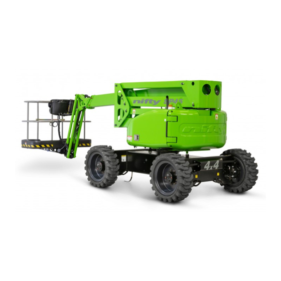
Driven from the basket, the Niftylift SP45 or SP50 is an extremely versatile articulated boom platform of unique and simple design. The SP45 can place two men and their tools at a height of 50ft 10in or an outreach of 30ft. -
Page 6: General Specification
SP Series Operating & Safety Instructions GENERAL SPECIFICATION FEATURE SP45 SP50 MAXIMUM HEIGHT - WORKING 51ft 6in 56ft 1in MAXIMUM HEIGHT - BASKET 45ft 1in 49ft 9in MAXIMUM OUTREACH 30ft 6in MAXIMUM HEIGHT – STOWED 6ft 9in MAXIMUM WIDTH 6ft 7in MAXIMUM LENGTH –... -
Page 7: Identification (Usa Plate)
SP Series Operating & Safety Instructions IDENTIFICATION (USA PLATE) This manufacturer’s plate is attached to the chassis on each machine at the time of manufacture on every Niftylift. Please ensure all sections have been stamped and are legible. USA – 11/14 Original instructions... -
Page 8: Safety
SP Series Operating & Safety Instructions Safety MANDATORY PRECAUTIONS When operating your Niftylift, your safety is of utmost concern. In order to fully appreciate all aspects of the machines operation it should be ensured that each operator has READ and fully UNDERSTOOD the relevant manual covering machine use, maintenance and servicing. - Page 9 SP Series Operating & Safety Instructions 2.1.8 This machine contains several hazardous substances such as but not limited to: Battery acid, Hydraulic Fluid, Engine Coolant, Antifreeze, LPG, Diesel Fuel, Engine Oil, Grease, Gasoline. 2.1.9 Covers and canopies should remain closed when the machine is in operation. Only trained personnel should carry out maintenance on the machine, ensuring at all times they protect themselves from electrical, heat and mechanical hazards.
- Page 10 SP Series Operating & Safety Instructions 2.1.20 Stunt driving and horseplay, on or around the Niftylift, shall not be permitted. 2.1.21 When other moving equipment and vehicles are present, special precautions shall be taken to comply with local ordinances or safety standards established for the work place. Warnings, such as but not limited to, flags, roped off areas, flashing lights and barricades shall be used.
-
Page 11: Environmental Limitations
SP Series Operating & Safety Instructions 2.1.37 The engine must be shut down while fuel tanks are being filled. Fuelling must be done in a well- ventilated area free of flame, sparks or any other hazard that may cause fire or explosion. GASOLINE , LIQUID PROPANE AND DIESEL FUELS ARE FLAMMABLE. -
Page 12: Noise And Vibration
SP Series Operating & Safety Instructions NOISE AND VIBRATION The airborne noise emission on the SP range of machines does not exceed 79dB(A), measured at a perpendicular distance of 12 feet, under equivalent continuous A-weighted sound pressure test conditions. This was based on a Diesel powered machine, working on high throttle, and under load. All other models will exhibit significantly lower emissions than this figure, dependant on power option. -
Page 13: Preparation And Inspection
SP Series Operating & Safety Instructions Preparation and Inspection UNPACKING Since the manufacturer has no direct control over the shipping or carriage of any Niftylift it is the responsibility of the dealer and/or owner and/or lessee to ensure the Niftylift has not been damaged in transit and a Pre-operational Report has been carried out by a qualified engineer before the Niftylift is put into service. -
Page 14: Pre-Operational Safety Check Schedules
SP Series Operating & Safety Instructions PRE-OPERATIONAL SAFETY CHECK SCHEDULES Before use each day and at the beginning of each shift the Niftylift shall be given a visual inspection and functional test including, but not limited to, the following: It is recommended that these be performed at regular intervals as indicated on each checklist. - Page 15 SP Series Operating & Safety Instructions 3.3.3 MONTHLY SAFETY CHECKS Check the engine oil level (if applicable). Check wheel nuts are secured (torque 110ft lbs / 150Nm). Check that the rotation worm is secured and correctly in mesh. Clean and re-grease. Check the track rod linkage.
- Page 16 SP Series Operating & Safety Instructions USA (SOUTH STATES), SOUTH AMERICA, AUSTRALIA (VICTORIA, NEW SOUTH WALES) 7.5 years USA (WEST STATES), SOUTH AFRICA, INDIA, PAKISTAN, IRAN, AUSTRALIA (WESTERN, 7 years SOUTH, QUEENSLAND) NORTH AFRICA, SAUDI, DUBAI, AUSTRALIA (NORTHERN TERRITORY) 6 years Note: The date of manufacture of the toughcage floor is located on its underside.
-
Page 17: Placard, Decals & Installation
SP Series Operating & Safety Instructions PLACARD, DECALS & INSTALLATION ITEM DESCRIPTION NUMBER Serial Plate P15383 Travel Direction P27047 No Step P14785 Charger Socket 240V P26425 P14697 P17124 Noise Warning 85dB General crush hazard P24914 Gearbox Disengage P18811 ‘Fitted with SiOPS’ P22820 Clunk Click P19961... - Page 18 Basket Tie-down Warning P21404 Level Sensor testing P23801 Logo - HR15 P24953 Logo - HR17 P24954 Power to basket socket 240V P26427 Point Load (HR15/SP45) 27.8kN P25881 Point Load (HR17/SP50) 30.2kN P25880 Tier 4/EU Stage IIIB P25407 Exhaust purification P25490...
- Page 19 SP Series Operating & Safety Instructions USA – 11/14 Original instructions...
-
Page 20: Torque Requirements
SP Series Operating & Safety Instructions TORQUE REQUIREMENTS BOLT QUALITY/SIZE Tightening torque in lbs ft (Nm) Plated Unplated Grade 10.9 12.9 10.9 12.9 5 (7) 8 (10) 9 (12) 6 (8) 8 (11) 10 (13) 13 (17) 18 (25) 22 (29) 14 (19) 20 (27) 23 (32) -
Page 21: Operation
SP Series Operating & Safety Instructions Operation CONTROL CIRCUIT COMPONENTS 4.1.1 GROUND CONTROLS MASTER PROGRAMMEABLE LOGIC CONTROLLER (PLC): - Situated under the ground controls canopy, behind the Ground Controls Station is the Master PLC. The main purpose of the Master PLC is to process signals received from all areas of the control circuit on the machine and where appropriate output these to a series of smaller digital modules to operate the relevant machine functions. - Page 22 SP Series Operating & Safety Instructions 4.1.2 BASKET BASKET PROGRAMMEABLE LOGIC CONTROLLER (PLC): - Situated in the basket is the Basket Control Station. Behind the basket control panel is the Basket PLC. The purpose of the Basket PLC is to interpret signals received from the Basket Control Station and convert them to a digital signal, which is then output to the Master PLC for processing.
- Page 23 SP Series Operating & Safety Instructions 4.1.5 FUSES & TRIP SWITCHES: - Power Tray 35A Circuit breaker inside ABS box 15A Circuit breaker inside ABS box Ground Control Station Basket Control Station 125A Fuse under Ground Control box 2 x 15A blade fuses behind Control Panel 2 x 15A blade fuses inside Ground Control Box 2 x 2A blade fuses behind Control Panel 1 x 2A blade fuse inside Ground Control Box...
-
Page 24: Ground Control Operation
SP Series Operating & Safety Instructions GROUND CONTROL OPERATION 4.2.1 GROUND CONTROL FUNCTIONS 1 Emergency Stop Push to Stop Operation Twist to Enable Operation 2 Green Power Button Push and hold for Power Release to Cease operation Indicates Safe Working Load limit or Maximum Tilt Angle exceeded. - Page 25 SP Series Operating & Safety Instructions Base Levers 1 Operates Basket Levelling Up for Backward ** Down for Forward ** 2 Operates the Flyboom Up for Up Down for Down 3 Operates Telescoping Up for Out Down for In 4 Operates the Link Booms Up for Up Down for Down 5 Operates the Upper Boom...
- Page 26 SP Series Operating & Safety Instructions ALL MODELS Push and hold green power button on the base control panel. Select a function or functions and operate the appropriate hydraulic levers in full accordance with manufacturers operating and safety manual. (Refer to Section 4.2.1) Note: Move lever until resistance is felt, then push/pull harder to activate function.
-
Page 27: Basket Control Operation
SP Series Operating & Safety Instructions BASKET CONTROL OPERATION 4.3.1 BASKET CONTROL FUNCTIONS Engine Glow/Start/Stop Anti-clockwise hold for Glow Clockwise to Start/Stop engine Speed Selector Anti-clockwise to decrease Clockwise to increase speed Basket rotation RH for Anti-clockwise LH for Clockwise Horn Press &... - Page 28 SP Series Operating & Safety Instructions 4.3.2 BASKET DISPLAY UNIT Situated on the Basket Control Panel, this gauge provides a warning indication for a range of functions. For further information refer to Section 4.3.3 ‘Information Icons’ on Page 27. During machine operation the gauge displays current fuel level, basket load status (if fitted), current boom/drive speed setting and usage hours.
- Page 29 SP Series Operating & Safety Instructions 4.3.3 INFORMATION ICONS Safety Critical Safe Working Load exceeded:- The alarm sounds and the display alternates between the images shown here. The Maximum SWL (500lbs) has been exceeded. Immediately remove any unnecessary items from the basket in a safe manner to restore machine functions.
- Page 30 SP Series Operating & Safety Instructions Diesel Engine Power Machine is in operation using engine power. Oil Pressure/Water Temperature Low engine oil pressure or high water temperature. Top-up may be necessary. Refer to Niftylift Service Manual for further information. Machine Usage Hours To access this screen, press button 2 (refer to Section 4.3.2).
- Page 31 SP Series Operating & Safety Instructions 4.3.4 OPERATION NEVER START THE NIFTYLIFT IF YOU SMELL GASOLINE, LIQUID PROPANE OR DIESEL. THESE FUELS ARE FLAMMABLE. BEFORE OPERATING THE NIFTYLIFT ENSURE THAT EACH OPERATOR HAS READ AND FULLY UNDERSTOOD THE OPERATING MANUAL. FAILURE TO DO SO MAY RESULT IN DEATH OR SERIOUS INJURY.
- Page 32 SP Series Operating & Safety Instructions 4.3.5 SiOPS - LOAD SENSING CONSOLE (If fitted) WHEN OPERATING THIS MACHINE THE USER MUST BE AWARE OF ANY OVERHEAD OBSTRUCTIONS. This machine incorporates a load sensing basket console that senses if the operator has been pushed or has fallen against the console.
-
Page 33: Driving Controls
Off-road (High Gradeability) - gives low speed, high engine revs and high gradeability. Note; High Drive Speed is only available when the booms are in the stowed position. The SP45/50 will default to Low Drive speed whenever the booms are elevated. If the machine is driven on slopes exceeding 10 it automatically reverts to Off-road speed (High Gradeability). -
Page 34: Basket Weigh System (If Fitted)
4.5.1 LOAD CELL VERSION The Niftylift SP45/50 is fitted with an electronic load cell. This load cell is a moment-independent, redundant design. This means that independent of the load position inside the machine basket, the actual load is measured and if pre-configured limit values are exceeded, warnings will be activated. -
Page 35: Transporting, Towing, Craneage, Storage And Setting To Work
SP Series Operating & Safety Instructions TRANSPORTING, TOWING, CRANEAGE, STORAGE AND SETTING TO WORK 4.6.1 TRANSPORTING If a Niftylift is to be moved over a longer distance, whether the machine is trailer mounted, vehicle mounted, self propelled or tracked, the following procedure should be read before restraints are attached to the machine. - Page 36 IDENTIFYING GEARBOX TYPE In order to safely tow the SP45/50, the drive mechanism will need to be bypassed. Identify the type of gearbox fitted to the machine then refer to the relevant procedure for disengagement of the gearboxes.
- Page 37 SP Series Operating & Safety Instructions GEARBOX DISENGAGEMENT (TYPE 2) The drive gearboxes located on the front and rear wheel hubs must be disengaged as follows; Remove both retaining bolts that secure the cover disc to the centre of the wheel hub. Partially screw one of the retaining bolts into the end of the central disengage pin and pull the pin out fully, ensuring the recess on the pin is visible.
- Page 38 SP Series Operating & Safety Instructions 4.6.4 STORAGE If being stored for any length of time without use, then the machine should be thoroughly inspected for the following:- Grease all bearings /slides, worm drives, etc. If machine is to be left on an incline, chock wheels to prevent creep. If machine is to be left outside or in a hostile environment, cover with suitable weatherproof media to prevent deterioration.
-
Page 39: Emergency Controls
SP Series Operating & Safety Instructions Emergency Controls GENERAL CHECKING THE OPERATION OF THE EMERGENCY CONTROLS EVERY DAY AND/OR BEFORE EACH SHIFT IS AN ESSENTIAL PART OF THE OPERATOR'S DUTIES The operator and all ground personnel must be thoroughly familiar with the location and operation of the emergency controls. -
Page 40: Responsibilities
SP Series Operating & Safety Instructions Responsibilities CHANGES IN OWNERSHIP When a change of ownership of a Niftylift occurs, it shall be the responsibility of the seller to notify Niftylift directly of the unit, model and serial number and the name and address of the new owner within 60 days. -
Page 41: Inspection/Service/Pre-Hire Check List
SP Series Operating & Safety Instructions INSPECTION/SERVICE/PRE-HIRE CHECK LIST MACHINE SERIAL NO TOWING PASS FAIL Machine secured on trailer Straps correctly positioned and tightened Wheels chocked if necessary AXLES, WHEELS AND BRAKES Wheels are secure, tire condition acceptable Wheel bearings O.K. Brake linkages and cables secure Brake shoe wear not excessive Machine climbs slope... - Page 42 SP Series Operating & Safety Instructions TILT ALARM PASS FAIL Booms raised on slope - drive disabled, siren tone constant Boom operation unaffected Booms lowered - drive restored INTERNAL (POWER PACK) Power pack and all components secure All cables and terminals secure All hose connections secure Hoses not kinked or fouled Charger/control box secure...
- Page 43 SP Series Operating & Safety Instructions Appendix A Code Fault Description Action Open circuit or short circuit of Check wiring to the base sounder Sounder Error the base sounder Check bulb is fitted. Open circuit or short circuit of Base Green Button, Bulb Error Check wiring to the base green the base green button bulb button bulb...
- Page 44 SP Series Operating & Safety Instructions Code Fault Description Action Check wiring from the debug core of the Error of the corresponding programming port. Debug Error digital input during PLC start up check - Reset power Check wiring from the 'base' side of the Error of the corresponding Key switch Base Switch key switch.
- Page 45 SP Series Operating & Safety Instructions Code Fault Description Action Check that there is around 60Ohms between CANH and CANL anywhere on the network The control system has Check there are no short circuits detected an error in the ERROR_CAN_SAFETY between CANH and CANL anywhere on communication between the the network...
- Page 46 SP Series Operating & Safety Instructions Code Fault Description Action Check paddle analogue voltages Paddle analogue outputs are Links Paddle Error Use another paddle to check inputs to not within spec of each other control system Check paddle analogue voltages Paddle analogue outputs are Luffing Paddle Error Use another paddle to check inputs to...
Need help?
Do you have a question about the SP45 and is the answer not in the manual?
Questions and answers