Table of Contents
Advertisement
Quick Links
Advertisement
Table of Contents

Related Manuals for Iluminarc LOGIC


Summary of Contents for Iluminarc LOGIC
- Page 1 Wall Panel 16-Port User Manual Model ID: LOGICWALLPANEL16PORT...
- Page 2 Chauvet has no obligation to make, and does not commit to make, any such revisions. Document Revision Go to www.iluminarc.com for the latest version. Revision Date Description 02/2024 Initial release.
-
Page 3: Table Of Contents
Rigging ....................... Wall Mounting ....................Rack mounting......................14 Panel Installation ..................... 14 Wall/Surface Mounting ..................Mounting Diagram ....................17 Knockouts ..................... Logic Wall Panel Expansion Kit 8-Port............Installation Instructions.................. Step 1......................... Step 2......................... Step 3......................... Step 4......................... Step 5......................... Step 6......................... - Page 4 Table of Contents Finished......................4. Operation ..................Control Panel Description ................Programming....................Password ......................Menu Map ..................... RDM Chart ....................Home Screen ....................Control Protocol .................... Local......................Output Status ..................... Net Switch ......................Universe ......................Password Lock ....................Priority ........................ History ........................
- Page 5 Table of Contents By date ........................42 By week ........................42 Enable Clock ...................... Fade In and Fade Out ..................Web Server ....................Home........................Status ......................... Fixture List......................Settings ......................Administrator Settings ..................Firmware Update ..................... 46 5. Maintenance................Product Maintenance ..................6.
-
Page 6: Before You Begin
Before You Begin 1. Before You Begin What Is Included • LΩGIC Wall Panel 16- Port • LΩGIC Wall Controller • Door keys (X2) • Quick Reference Guide Claims Carefully unpack the product immediately and check the container to make sure all the parts are in the package and are in good condition. -
Page 7: Safety Notes
Before You Begin Safety Notes These Safety Notes include important information about installation, use, and maintenance of the LΩGIC Wall Panel 16- Port. This product contains no user-serviceable parts. Any reference to servicing in this User Manual will only apply to properly trained, certified technicians. Do not open the housing or attempt any repairs. -
Page 8: Fcc Statement Of Compliance
Before You Begin FCC Statement of Compliance This device complies with Part 15 Part B of the FCC rules. Operation is subject to the following two conditions: 1. This device may not cause harmful interference, and 2. This device must accept any interference received, including interference that may cause undesired operation. -
Page 9: Introduction
92.5 W/port. The Wall Panel can be expanded up to 32-ports using the 8- port expansion kits. The LΩGIC Wall Panel 16- Port includes one LOGIC Wall Con, which is a single gang wall controller that can recall up to 8 recorded scenes from the Wall Panel. Additional Wall Cons may be added to the system, up to 32 pcs on a single controller to have multiple control locations. -
Page 10: Product Overview
Push to enable the currently displayed menu option or set the currently selected value into the selected function. <BACK> button Exits the current menu or function LOGIC FIXTURE IEEE 802.3bt POE RJ45 connector for output LΩGIC products OUTPUTS 5 WALL CON OUTPUT 1/ RJ12 connectors for LΩGIC Wall Controller... -
Page 11: Side Overview
Introduction Side Overview 2 in 51 mm 1.75 in 44 mm 1.5 in 38 mm 1.25 in 32 mm 1 in 25 mm knockout dimensions LΩGIC Wall Panel 16- Port User Manual Rev. 1... -
Page 12: Product Dimensions
Introduction Product Dimensions 8.78 in 20.63 in 223 mm 524 mm 17.32 in 440 mm 35.43 in 900 mm 8.66 in 220 mm LΩGIC Wall Panel 16- Port User Manual Rev. 1... -
Page 13: Setup
Setup 3. Setup AC Power The LΩGIC Wall Panel 16- Port has an auto-ranging power supply and it can work with an input voltage range of 200 to 240 VAC, 50/60 Hz. To determine the product’s power requirements (circuit breaker, power outlet, and wiring), use the current value listed on the label affixed to the product’s back panel, or refer to the Technical Specifications. -
Page 14: Lωgic Wall Controller
Setup LΩGIC Wall Controller Each LΩGIC Wall Panel 16- Port comes with a LΩGIC Wall Controller which can plug into the RJ12 connector on the back of the product. • Buttons 1–8 trigger playback of the corresponding recorded scenes (see Record). •... -
Page 15: Signal Connections
For more information about DMX standards or the DMX cables needed to link this product to a DMX controller, download the DMX Primer from the Chauvet website: www.iluminarc.com. DMX Linking The LΩGIC Wall Panel 16- Port will work with a DMX controller using a 5-pin phoenix connector. For more information about DMX, read the DMX primer at: https://www.chauvetprofessional.com/wp-content/... -
Page 16: Art-Net™ Connection
Art-Net™ is an Ethernet protocol that uses UDP/IP which transfers a large amount of DMX512 data using an ethernet connection over a large network. An Art-Net™ protocol document is available from www.iluminarc.com. Art-Net™ designed by and copyright Artistic Licence Holdings Ltd. -
Page 17: Lωgic Product Chaining
Setup LΩGIC Product Chaining The LΩGIC Wall Panel 16- Port powers and controls each connected LΩGIC product via a Power Over Ethernet (POE) connection. When linking LΩGIC products to the LΩGIC Wall Panel 16- Port, there is a set maximum number of each LΩGIC product which can be powered by a single port. Power Consumption Product Capacity per Port/POE... -
Page 18: Mixing Lωgic Products
THRU: for long-distance transmission. Outputs only the control signal from the LΩGIC Wall Panel 16- Port, no power. A POE injector must be used BEFORE the first LOGIC product in the chain to power it and further products connected to this port. -
Page 19: Mounting
Setup Mounting Before mounting the product, read and follow the safety recommendations indicated in the Safety Notes. Orientation Always mount this product in a safe position, making sure there is adequate room for ventilation, configuration, and maintenance. Rigging Chauvet recommends using the following general guidelines when mounting this product. •... - Page 20 Setup 3. Carefully insert the LΩGIC Wall Panel 16- Port into the rack mount. More than one person should participate in moving the panel onto the rack mount. Attempts to do so alone may result in damage to the product and/or serious injury. 4.
- Page 21 Setup 5. Holding the LΩGIC Wall Panel 16- Port firmly in place, attach the product to the rack mount with 1/ 4 in, 3/8 in, or 5/16 in screws/bolts. Ensure that the enclosure sits level and can support the weight of the product. Failure to do so may result in damage to the product and/or serious injury.
-
Page 22: Wall/Surface Mounting
Setup Wall/Surface Mounting The LΩGIC Wall Panel 16- Port may be directly attached to a wall/surface. To mount the product directly to a wall/surface: For maximum security, it is recommended to place the mounting hardware so they are at an equal height and the spacing between them is horizontal. 1. -
Page 23: Knockouts
Setup Knockouts The LΩGIC Wall Panel 16- Port has numerous knockouts. Knockouts are partially stamped removable openings in electrical enclosures and boxes. Knockouts are pre-designed and can be removed in order to allow electrical wiring to run through the enclosure. To remove a knockout from the LΩGIC Wall Panel 16- Port: 1. -
Page 24: Logic Wall Panel Expansion Kit 8-Port
Logic Wall Panel Expansion Kit 8-Port The Logic Wall Panel Expansion Kit 8-Port allows users to add 8 output ports to the LΩGIC Wall Panel 16- Port. A maximum of 2 Expansion Kits may be added to the LΩGIC Wall Panel 16- Ports in a single box. -
Page 25: Step 2
Setup Step 2 1. Carefully remove the breaker cover and open the service access panel. Breaker cover Service access panel 2. Remove the applicable plugs from the breaker cover and service access panel. First Expand Kit plugs Second Expand Kit First Expand Kit plug plug... -
Page 26: Step 3
Setup Step 3 1. Use a #2 Phillips-head screwdriver to install the 8-port POE output board with the 6 screws. Master control board 8-port POE output board (in the first Expand Kit slot) 2. Use a #2 Phillips-head screwdriver to install the output board power cables. •... -
Page 27: Step 4
Setup Step 4 1. Identify the ribbon cable port on the master control board which corresponds with the Expand Kit slot. 2. Open the applicable ribbon cable ports on the 8-port POE output board and on the master control board. First Expand Kit ribbon cable port Second Expand Kit... -
Page 28: Step 5
Setup Step 5 1. Use a #2 Phillips-head screwdriver to install the power supply with the 4 screws. 2. Use a #2 Phillips-head screwdriver to install the AC power cables on the left of the power supply. • Connect the white cable to the terminal marked “AC/N”. •... -
Page 29: Step 6
Setup Step 6 1. Use a #2 Phillips-head screwdriver to loosen the left-most rail clamp and slide it off the rail. 2. Slide the Expand Kit DIN rail breaker onto the rail until it is up against the adjacent DIN rail breaker. -
Page 30: Step 7
Setup Step 7 1. Carefully fit the breaker cover over the DIN rail breakers and close the service access panel. 2. Use a #2 Phillips-head screwdriver and a 2.5 mm hex wrench to install the previously removed screws. LΩGIC Wall Panel 16- Port User Manual Rev. 1... -
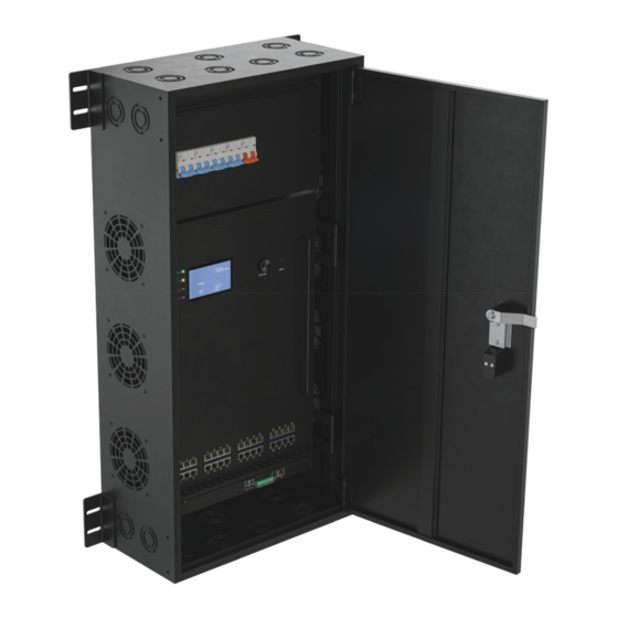
Page 31: Finished
Setup Finished 1 LOGIC Wall Panel Expansion Kit8 has been installed in the above image. It is possible to install up to 2 LOGIC Wall Panel Expansion Kit8 products in each LΩGIC Wall Panel 16- Port. LΩGIC Wall Panel 16- Port User Manual Rev. 1... -
Page 32: Operation
Password After being prompted to enter the password, use the <MENU> knob to select and enter 123456. Menu Map Refer to the LΩGIC Wall Panel 16- Port product page on www.iluminarc.com for the latest menu maps and software. Main Programming Levels... - Page 33 Shows length of time product _ _minutes Hours has been on _ _ seconds Label LOGIC Wall Panel Shows device label Device UID _ _ _ _ _ _-_ _ _ _ _ _ _ _ Shows device UID MAC Address...
- Page 34 Operation Main Programming Levels Description Level Displays order of connected Order 1- _ fixtures Output 1-32 Displays fixture port Model _ _ _ _ _ Displays fixture name 1-channel: dimmer (red only) GREEN 1-channel: dimmer (green only) BLUE 1-channel: dimmer (blue only) WHITE 1-channel: dimmer 2-channel, Tunable White:...
- Page 35 Operation Main Programming Levels Description Level Turn on Turn off Schedules daily times to turn on Everyday and off (stackable with other 00–23:00–59:00–59 schedule options) Turn on Turn off Month:01 Month:01–12 –12 Schedules a date and time to By date turn on and off (stackable with Day:01–...
-
Page 36: Rdm Chart
URE_FIXED; 4, Software Version ID; 5, DMX512 Footprint; 6, DMX512 Personality; Product 7, DMX512 Start Address; Information 8, Sensor Count; PRODUCT_DETAIL_ID_LIST 0x0070 DEVICE_MODEL_DESCRIPTION 0x0080 LOGIC WALL PANEL MANUFACTURER_LABEL 0x0081 ILUMINARC DEVICE_LABEL 0x0082 LOGIC WALL PANEL 0x00C SOFTWARE_VERSION_LABEL V_._... -
Page 37: Home Screen
LΩGIC products, IP address, and date as set on the internal calendar. The home screen will also indicate if the System Clock has placed the product in Shut off mode. To see the home screen, press <ESC/BACK> repeatedly until it shows on the display. Illuminarc Control Protocol Logic Wall Panel 1/17/2024 IP: 2.101.0.48 12:08:55 Online:... -
Page 38: Priority
Operation Priority To select whether input from a LΩGIC Wall Controller or input from a control signal (DMX, Art-Net™, or sACN) will take priority over the other: 1. Go to the Local main menu. 2. Select the Priority option. 3. Select from Control Panel or Signal. The selected option will have priority. History The LΩGIC Wall Panel 16- Port keeps a record of all LΩGIC products to which it has linked. -
Page 39: Linked Fixture
4. Select the desired LΩGIC product. The selected product will flash its LEDs for the duration it is being accessed. Refer to the LΩGIC Wall Panel 16- Port product page and the product page for the selected for the latest menu maps and software. LΩGIC product on www.iluminarc.com Main Level Programming Levels Description Dmx Address 001–512... -
Page 40: Individual Lωgic Product Configuration
Operation Individual LΩGIC Product Configuration Individual Control Personality To set the control personality individually for the selected LΩGIC product: 1. From the menu of the selected LΩGIC product, select the Personality option. 2. Select the desired personality, from RED, GREEN, BLUE, WHITE, TW, RGB, RGBW, RGBW+D, or FULL. -
Page 41: Renew
Operation Renew To re-scan for connected LΩGIC products: 1. Go to the Linked Fixture main menu. 2. Select Status. 3. Select Renew. 4. Select from No (cancel) or Yes (renew). Control Personality (Global) To set the control personality of all connected LΩGIC products at once: 1. -
Page 42: Control Channel Assignments And Values
Operation Control Channel Assignments and Values FULL (10 Channels) Channel Function Value Percent/Setting Dimmer 000 255 0–100% 000 255 0–100% Green 000 255 0–100% Blue 000 255 0–100% White 000 255 0–100% 000 010 No function 011 ... -
Page 43: Rgbw+D (5 Channels)
Operation RGBW+D (5 Channels) Channel Function Value Percent/Setting Dimmer 000 255 0–100% 000 255 0–100% Green 000 255 0–100% Blue 000 255 0–100% White 000 255 0–100% RGBW (4 Channels) Channel Function Value Percent/Setting 000 255 0–100% Green 000 ... -
Page 44: White (1 Channel)
Operation WHITE (1 Channel) Channel Function Value Percent/Setting Dimmer 000 255 White only, 0–100% BLUE (1 Channel) Channel Function Value Percent/Setting Dimmer 000 255 Blue only, 0–100% GREEN (1 Channel) Channel Function Value Percent/Setting Dimmer 000 255 Green only, 0–100% RED (1 Channel) Channel Function... -
Page 45: Record
Operation Record The LΩGIC Wall Panel 16- Port can record control signal input (DMX, Art-Net™, or sACN) for later playback through the display menu or by a connected LΩGIC Wall Controller. The LΩGIC Wall Panel 16- Port has 64 recording slots. When a scene is triggered for playback, it will play continuously until it is stopped or another recording is triggered. -
Page 46: Erase Recording
Operation Erase Recording To erase a recording slot: 1. Go to the Record main menu. 2. Select the Record Erase option. 3. Select the desired recording slot, from Record1–8 Clr. 4. Select from No (cancel) or Yes (erase the selected recording slot). System Clock The system clock functions allow the LΩGIC Wall Panel 16- Port to place itself in or out of Shut off mode on a set schedule. -
Page 47: By Date
Operation By date To set specific dates to turn on and off: 1. Go to the System Clock main menu. 2. Select the Schedule option. 3. Select the By date option. 4. Review the current settings. To begin editing them, press the <MENU> knob. After setting each option, press the <MENU>... -
Page 48: Web Server
Operation Web Server The LΩGIC Wall Panel 16- Port web server can be accessed by any computer on the same network as the product. It allows network access to system information, settings such as product addressing, static color testing, and calendar triggers, as well as firmware updates for both the LΩGIC Wall Panel 16- Port and any connected LΩGIC products. -
Page 49: Status
Operation Status The STATUS screen displays the information available in the Local Information Output Status sections of the display menu. Fixture List The FIXTURE LIST screen displays information for each connected LΩGIC product which has been detected by the LΩGIC Wall Panel 16- Port and provides the following control options: •... -
Page 50: Settings
Operation Settings The SETTINGS screen displays and provides 5 types of control options: • Basic: displays and sets the control Protocol, the first value of the IP address (Net switch) for the LΩGIC Wall Panel 16- Port, the control Personality, and the Universe address if applicable. Click Save to send any changed settings to the LΩGIC Wall Panel 16- Port. -
Page 51: Administrator Settings
The procedure for updating the firmware of the LΩGIC Wall Panel 16- Port is identical to the procedure for updating the firmware of connected LΩGIC products. 1. Download the latest firmware files from www.iluminarc.com. 2. Access the web server for LΩGIC Wall Panel 16- Port according to the instructions under Server. -
Page 52: Maintenance
Maintenance 5. Maintenance Product Maintenance Dust build-up reduces light output performance and can cause overheating. This can lead to reduction of the light source’s life and/or mechanical wear. To maintain optimum performance and minimize wear, clean all lighting products at least twice a month. However, be aware that usage and environmental conditions could be contributing factors to increase the cleaning frequency. -
Page 53: Technical Specifications
Technical Specifications 6. Technical Specifications Dimensions and Weight Length Width Height Weight 10.31 in (479 mm) 18.86 in (245 mm) 1.73 in (44 mm) 75 lb (34 kg) Note: Dimensions in inches are rounded. Power Power Supply Type Range Voltage Selection Switching (internal) 200 to 240 VAC, 50/60 Hz Auto-ranging... -
Page 54: Contact Us
Contact Us Contact Us General Information Technical Support Chauvet World Headquarters Address: 3360 Davie Rd., Suite 509 Voice: (844) 393-7575 Davie, FL 33314 Fax: (954) 756-8015 Voice: (954) 577-4455 Email: chauvetcs@chauvetlighting.com Fax: (954) 929-5560 Toll Free: (800) 762-1084 Website: www.chauvetprofessional.com Chauvet U.K.
Need help?
Do you have a question about the LOGIC and is the answer not in the manual?
Questions and answers