
Related Manuals for Beckhoff EP4378-1022


Summary of Contents for Beckhoff EP4378-1022
- Page 1 Documentation | EN EP4378-1022 EtherCAT Box with 4 analog inputs, 4 analog outputs, 8 digital inputs/ outputs 2024-03-08 | Version: 1.4...
-
Page 3: Table Of Contents
Analog outputs .......................... 56 5.3.1 Signal flow........................ 56 5.3.2 Output signal range...................... 57 5.3.3 Behavior in case of a communication interruption: Watchdog ......... 58 5.3.4 Calibration and scaling..................... 61 Restore the delivery state ....................... 64 Decommissioning .......................... 65 EP4378-1022 Version: 1.4... - Page 4 Version identification of EtherCAT devices .................. 75 7.4.1 General notes on marking.................... 75 7.4.2 Version identification of IP67 modules ................ 76 7.4.3 Beckhoff Identification Code (BIC) ................... 77 7.4.4 Electronic access to the BIC (eBIC)................. 79 Support and Service........................ 81 Version: 1.4 EP4378-1022...
-
Page 5: Foreword
All the components are supplied in particular hardware and software configurations appropriate for the application. Modifications to hardware or software configurations other than those described in the documentation are not permitted, and nullify the liability of Beckhoff Automation GmbH & Co. KG. Personnel qualification This description is only intended for trained specialists in control, automation and drive engineering who are familiar with the applicable national standards. -
Page 6: Notes On The Documentation
, XTS and XPlanar are registered trademarks of and licensed by Beckhoff Automation GmbH. Other designations used in this publication may be trademarks whose use by third parties for their own purposes could violate the rights of the owners. Patent Pending... -
Page 7: Documentation Issue Status
YY - year of production 10 - year of production 2010 FF - firmware version 02 - firmware version 02 HH - hardware version 01 - hardware version 01 Further information on this topic: Version identification of EtherCAT devices [} 75]. EP4378-1022 Version: 1.4... -
Page 8: Ethercat Box - Introduction
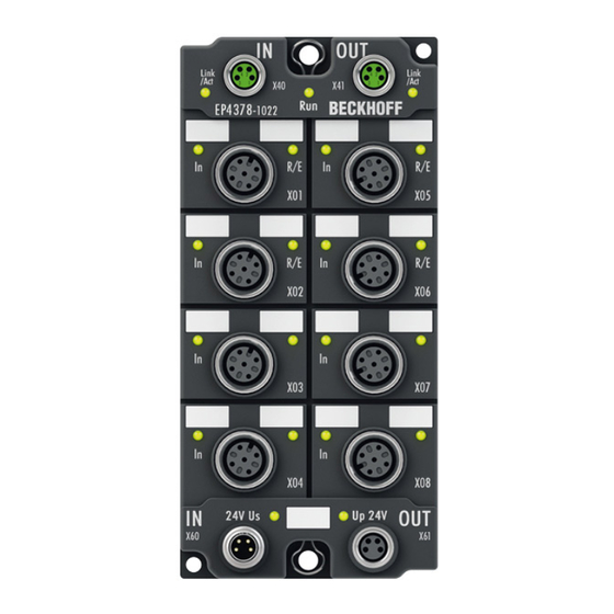
• digital outputs with 0.5 or 2 A output current • analog inputs and outputs with 16 bit resolution • Thermocouple and RTD inputs • Stepper motor modules XFC (eXtreme Fast Control Technology) modules, including inputs with time stamp, are also available. Version: 1.4 EP4378-1022... - Page 9 Fig. 3: EtherCAT Box with M12 connections for sensors/actuators Basic EtherCAT documentation You will find a detailed description of the EtherCAT system in the Basic System Documentation for EtherCAT, which is available for download from our website (www.beckhoff.com) under Downloads. EP4378-1022 Version: 1.4...
-
Page 10: Product Overview
EP4378-1022 | 4+4-channel analog input/output, U/I parameterisable, + 8-channel digital input/output, 24 V DC/3.0 ms The EP4378-1022 EtherCAT Box provides a combination of four analog inputs and four analog outputs as well as eight digital inputs/outputs. The analog channels can be individually parameterised so that they process/generate signals either in the ±10 V or the 0/4 to 20 mA range. - Page 11 Product overview Quick links Technical data [} 12] Process image [} 23] Dimensions [} 26] Connector overview [} 28] Analog inputs [} 42] Analog outputs [} 56] EP4378-1022 Version: 1.4...
-
Page 12: Technical Data
EN 60068-2-6 / EN 60068-2-27 Additional tests [} 13] EMC immunity / emission conforms to EN 61000-6-2 / EN 61000-6-4 Protection class IP65, IP66, IP67 (conforms to EN 60529) Approvals/markings Approvals/markings CE, cURus [} 39] *) Real applicable approvals/markings see type plate on the side (product marking). Version: 1.4 EP4378-1022... -
Page 13: Analog Inputs
Output error < 0.1% (ambient temperature 0 ... +55°C) < 0.2% (ambient temperature < 0°C and > 55°C) of the full scale value of the signal range. Load resistor / load Voltage output: min. 5 kΩ Current output: max. 350 Ω Short-circuit proof EP4378-1022 Version: 1.4... -
Page 14: Digital Inputs/Outputs
Similar to type 3 according to EN 61131-2, compatible with type 1 Input filter 3.0 ms Input current 3 mA at 24 V Output specification Load type ohmic, inductive, lamp load Output voltage 24 V from the peripheral voltage U Output current max. 0.5 A per output, short-circuit proof max. 4 A in total Version: 1.4 EP4378-1022... -
Page 15: Measuring Ranges
Optional: "Legacy Range" mode Calculated resolution: 305.19 µV /Step -10 V +10 V -32768 +32767 (0x8000) (0x0000) (0x7FFF) negative Range positive Range Range Error Range Error Limit (² Limit (² Underrange Overrange Limit (¹ Limit (¹ Nominal / Technical Range EP4378-1022 Version: 1.4... - Page 16 ² Range Error: Error Bit + Error LED (detection level adjustabel by user, default: technical range) Optional: "Legacy Range" mode Calculated resolution: 305.19 µV /Step +10 V +32767 (0x0000) (0x7FFF) positive Range Range Error Range Error Limit (² Limit (² Underrange Overrange Limit (¹ Limit (¹ Nominal / Technical Range Version: 1.4 EP4378-1022...
- Page 17 Calculated resolution: 610.37 nA /Step -20 mA 0 mA +20 mA -32768 +32767 (0x8000) (0x0000) (0x7FFF) negative Range positive Range Range Error Range Error Limit (² Limit (² Underrange Overrange Limit (¹ Limit (¹ Nominal / Technical Range EP4378-1022 Version: 1.4...
- Page 18 ² Range Error: Error Bit + Error LED (detection level adjustabel by user, default: technical range) Optional: "Legacy Range" mode Calculated resolution: 610.37 nA /Step 0 mA +20 mA +32767 (0x0000) (0x7FFF) positive Range Range Error Range Error Limit (² Limit (² Underrange Overrange Limit (¹ Limit (¹ Nominal / Technical Range Version: 1.4 EP4378-1022...
- Page 19 ² Range Error: Error Bit + Error LED (detection level adjustabel by user, default: technical range) Optional: "Legacy Range" mode Calculated resolution: 488.30 nA /Step +4 mA +20 mA +32767 (0x0000) (0x7FFF) positive Range Range Error Range Error Limit (² Limit (² Underrange Overrange Limit (¹ Limit (¹ Nominal / Technical Range EP4378-1022 Version: 1.4...
-
Page 20: Output Signal Ranges
Output signal range 0...10 V Full scale value of the signal range 10 V PDO resolution 16-bit, including sign PDO LSB 305.19 µV Calculated resolution: 305.19 µV /Step +10 V +32767 (0x0000) (0x7FFF) positive Range Nominal / Technical Range Version: 1.4 EP4378-1022... - Page 21 Output signal range 4...20 mA Full scale value of the signal range 20 mA PDO resolution 16-bit, including sign PDO LSB 488.30 nA Calculated resolution: 488.30 nA /Step 4 mA +20 mA +32767 (0x0000) (0x7FFF) positive Range Nominal / Technical Range EP4378-1022 Version: 1.4...
-
Page 22: Scope Of Supply
Scope of supply Make sure that the following components are included in the scope of delivery: • 1x EtherCAT Box EP4378-1022 • 2x protective cap for EtherCAT socket, M8, green (pre-assembled) • 1x protective cap for supply voltage input, M8, transparent (pre-assembled) •... -
Page 23: Process Image
The process image contains a process data object for each input and each output. The designation of each process data object contains the name of the socket and the pin number of the corresponding input or output. See Connector overview [} 28]. Fig. 4: EP4378-1022 process image „DI“: Process data of the digital inputs Input Digital input. - Page 24 "Value" is invalid. • TxPDO Toggle The box inverts this bit every time it updates the measured value "Value" in the process data. Value The current measured value. Data type: INT. Data format: ajustable [} 47] (factory setting: Signed Integer) Version: 1.4 EP4378-1022...
- Page 25 Product overview „DO“: Process data of the digital outputs Output Digital output. Data type: BIT. „AO“: Process data of the analog outputs Analog output Analog output. Data type: INT. EP4378-1022 Version: 1.4...
-
Page 26: Mounting And Connection
Metal parts brass, nickel-plated Contacts CuZn, gold-plated Installation position variable Protection class IP65, IP66, IP67 (conforms to EN 60529) when screwed together Dimensions (H x W x D) approx. 126 x 60 x 26.5 mm (without connectors) Version: 1.4 EP4378-1022... -
Page 27: Fixing
The Fixing [} 27] also serve as connections for the functional earth (FE). Make sure that the box is earthed with low impedance via both fastening screws. You can achieve this, for example, by mounting the box on a grounded machine bed. EP4378-1022 Version: 1.4... -
Page 28: Connections
Supply voltage input [} 31] M8 socket 0.4 Nm Supply voltage downstream connection [} 31] Mount plugs on these connectors using a torque wrench, e.g. ZB8801 from Beckhoff. Protective caps • Seal unused connectors with protective caps. • Ensure the correct seating of pre-assembled protective caps. -
Page 29: Ethercat
For standardization, the core colors of the ZB9030, ZB9032 and ZK1090-3xxx-xxxx cables have been changed to the EN61918 core colors: yellow, orange, white, blue. So there are different color codes in circulation. The electrical properties of the cables have been retained when the core colors were changed. EP4378-1022 Version: 1.4... - Page 30 (CAT5) according to EN 50173 or ISO/IEC 11801 should be used. EtherCAT uses four wires for signal transmission. Thanks to automatic line detection ("Auto MDI-X"), both symmetrical (1:1) or cross-over cables can be used between Beckhoff EtherCAT. Detailed recommendations for the cabling of EtherCAT devices Version: 1.4...
-
Page 31: Supply Voltages
In some types of EtherCAT Box modules the ground potentials GND and GND are connected. • If several EtherCAT Box modules are supplied with the same electrically isolated voltages, check whether there is an EtherCAT Box among them in which the ground potentials are connected. EP4378-1022 Version: 1.4... - Page 32 Brown Peripheral voltage White GND to U Blue GND to U Black The core colors apply to cables of the type: Beckhoff ZK2020-3xxx-xxxx 4.2.3.2 Status LEDs Fig. 10: Status LEDs for the supply voltages Display Meaning (control voltage) The supply voltage U is not available.
- Page 33 Vert. Faktor: 0,45 cm / V Vert. Faktor: 0,4 0.34 mm² Vert. Faktor: 0,45 cm / V Vert. Faktor: 0.5 mm² 0.25 mm² 0.34 mm² 0.75 mm² 0.5 mm² 0.75 mm² Cable length (m) Cable length (m) EP4378-1022 Version: 1.4...
-
Page 34: Signal Inputs And Outputs
M12 sockets NOTICE Risk of confusion The M12 sockets of the EP4378-1022 are configured differently. Defects are possible due to confusing the M12 sockets. EMC shield clamp Depending on the application it may be necessary to additionally attach the shield of the sensor cables at the signal inputs of the box with shield clamps ZB8513-0002. - Page 35 Pin 1 AOUT Pin 5 Pin 3 If the actuator has separate connections for supply GND and signal GND, connect the two GNDs with each other. This connection is shown by the dashed line in the figure. EP4378-1022 Version: 1.4...
- Page 36 Mounting and connection 4.2.4.4 Digital sensors, connection examples Two-wire connection 24 V Pin 1 Pin 4 Three-wire connection 24 V Pin 1 Pin 4 Pin 3 4.2.4.5 Digital actuators, connection examples Two-wire connection Pin 2 Pin 3 Version: 1.4 EP4378-1022...
- Page 37 Mounting and connection Three-wire connection 24 V Pin 1 Pin 4 Pin 3 EP4378-1022 Version: 1.4...
- Page 38 The measured value of the analog input is outside of the error thresholds. The analog output cannot drive the specified current. Possible reasons: • Wire breakage. • The load is too high. Permissible load: See Technical data for the output signal range [} 20]. x = no meaning Version: 1.4 EP4378-1022...
-
Page 39: Ul Requirements
To meet the UL requirements, EtherCAT Box Modules has to be operated only at an ambient temperature range of -25 °C to +55 °C! Marking for UL All EtherCAT Box Modules certified by UL (Underwriters Laboratories) are marked with the following label. Fig. 12: UL label EP4378-1022 Version: 1.4... -
Page 40: Disposal
Products marked with a crossed-out wheeled bin shall not be discarded with the normal waste stream. The device is considered as waste electrical and electronic equipment. The national regulations for the disposal of waste electrical and electronic equipment must be observed. Version: 1.4 EP4378-1022... -
Page 41: Commissioning And Configuration
Commissioning and configuration Commissioning and configuration Integrating into a TwinCAT project The procedure for integration in a TwinCAT project is described in this Quick start guide. EP4378-1022 Version: 1.4... -
Page 42: Analog Inputs
0x81n0:0E 0xA1n0:01 Measuring Limit value ADC raw value range monitoring monitoring Signal Vendor User User Filter Formatting conditioning calibration calibration scale 0x81n0:0A 0x81n0:01 0x81n0:06 0x81n0:02 0x81n0:0B 0x81nD:11 0x81n0:17 0x81n0:11 0x81n0:15 0x81nD:12 0x81nF:xx 0x81n0:18 0x81n0:12 Fig. 13: Signal flow Version: 1.4 EP4378-1022... -
Page 43: Measuring Range
Measuring range (factory setting) -10 … +10 V 0 … 10 V -20 … +20 mA 0 … 20 mA 4 … 20 mA The specifications for the individual measuring ranges can be found in the Technical Data [} 12]. Example Fig. 14: "Input Type" CoE parameter for the analog input at connection X01 EP4378-1022 Version: 1.4... - Page 44 Scaler Possible values Value Enum Description 0 (factory setting) „Extended Range“ Measuring range = technical measuring range „Legacy Range“ Measuring range = nominal measuring range Example Fig. 15: "Scaler" CoE parameter for the analog input at connection X01 Version: 1.4 EP4378-1022...
- Page 45 If the status bit “Error” is set: • The current measured value is smaller than the lower error threshold [} 46] or larger than the upper error threshold [} 46]. • The LED “A” [} 38]lights up red. It is linked to the status bit “Error”. EP4378-1022 Version: 1.4...
- Page 46 Upper error threshold Connection CoE object Parameter 810D AI Advanced Settings Ch.1 High Range Error 811D AI Advanced Settings Ch.2 High Range Error 812D AI Advanced Settings Ch.3 High Range Error 813D AI Advanced Settings Ch.4 High Range Error Version: 1.4 EP4378-1022...
-
Page 47: Data Format Of The Measured Values
Only positive measured values are displayed. The MSB is always 0. "Absolute MSB sign" Display as absolute value with the MSB as the sign bit. Example Fig. 16: "Presentation" CoE parameter for the analog input at connection X01 EP4378-1022 Version: 1.4... -
Page 48: Filter
• If all filters are disabled, the device runs in the synchronization mode "Synchron with SM event" • If one or more filters are enabled, the device runs in the synchronization mode "Free Run". Example Fig. 17: "Enable filter" CoE parameter for the analog input at connection X01 Version: 1.4 EP4378-1022... - Page 49 The filter with IIR characteristics is a discrete time, linear, time invariant filter that can be set to eight levels (level 1 = weak recursive filter, up to level 8 = strong recursive filter) The IIR can be understood to be a moving average value calculation after a low-pass filter. EP4378-1022 Version: 1.4...
- Page 50 Commissioning and configuration Example Fig. 18: "Filter settings" CoE parameter for the analog input at connection X01 Version: 1.4 EP4378-1022...
-
Page 51: Limit Value Monitoring
AI Settings Ch.1 Enable limit 1 Enable limit 2 8110 AI Settings Ch.2 Enable limit 1 Enable limit 2 8120 AI Settings Ch.3 Enable limit 1 Enable limit 2 8130 AI Settings Ch.4 Enable limit 1 Enable limit 2 EP4378-1022 Version: 1.4... - Page 52 "Swap limit bits" is a CoE parameter. "Swap limit bits" is FALSE in the factory setting. Connection CoE object Parameter 8100 AI Settings Ch.1 Swap limit bits 8110 AI Settings Ch.2 Swap limit bits 8120 AI Settings Ch.3 Swap limit bits 8130 AI Settings Ch.4 Swap limit bits Version: 1.4 EP4378-1022...
-
Page 53: Calibration And Scaling
Set the following CoE parameters to FALSE to disable the vendor calibration for the respective input. Connection CoE object Parameter 8100 AI Settings Ch.1 Enable vendor calibration 8110 AI Settings Ch.2 Enable vendor calibration 8120 AI Settings Ch.3 Enable vendor calibration 8130 AI Settings Ch.4 Enable vendor calibration EP4378-1022 Version: 1.4... - Page 54 AI Settings Ch.1 User calibration offset User calibration gain 8110 AI Settings Ch.2 User calibration offset User calibration gain 8120 AI Settings Ch.3 User calibration offset User calibration gain 8130 AI Settings Ch.4 User calibration offset User calibration gain Version: 1.4 EP4378-1022...
- Page 55 AI Settings Ch.1 User scale offset User scale gain 8110 AI Settings Ch.2 User scale offset User scale gain 8120 AI Settings Ch.3 User scale offset User scale gain 8130 AI Settings Ch.4 User scale offset User scale gain EP4378-1022 Version: 1.4...
-
Page 56: Analog Outputs
Commissioning and configuration Analog outputs 5.3.1 Signal flow 0xA1n0:01 DAC raw value User User Vendor Signal scale calibration calibration conditioning 0x81n0:01 0x81n0:07 0x81n0:08 0x81nD:11 0x81n0:11 0x81n0:15 0x81nF:xx 0x81n0:12 0x81n0:16 Version: 1.4 EP4378-1022... -
Page 57: Output Signal Range
AO Advanced Settings Ch.3 Output Type 817D AO Advanced Settings Ch.4 Output Type Possible values Value Output signal range (factory setting) -10 … +10 V 0 … 10 V 0 … 20 mA 4 … 20 mA Example Fig. 19: "Output Type" CoE parameter for the analog output at connection X01 EP4378-1022 Version: 1.4... -
Page 58: Behavior In Case Of A Communication Interruption: Watchdog
CAUTION Actuators may start to move unexpectedly if a Watchdog is active Injuries are possible. 1. Click the IO module EP4378-1022 under the entry "I/O" in the Solution Explorer. 2. Select the "EtherCAT" tab. 3. Click the "Advanced Settings" button. - Page 59 Select reaction times that are long enough to prevent the watchdogs from reacting even to very short, temporary communication interruptions. The reaction times are calculated with this equation: : Reaction time of a watchdog : Watchdog multiplier : Base multiplier (factory setting: 2498 EP4378-1022 Version: 1.4...
- Page 60 Time in ms until the default value is reached. current default ramp : the last output value that was received by the current controller before the communication interruption. : Default value (CoE parameter 81n0:13). default : Ramp speed in digits/ms (CoE parameter ramp 81n0:14). Version: 1.4 EP4378-1022...
-
Page 61: Calibration And Scaling
If you use the user calibration [} 62], it may be a good idea to disable the vendor calibration. Set the relevant "Enable vendor calibration" CoE parameters to FALSE to disable the vendor calibration for the respective output. Connection "Enable vendor calibration" 0x8130:08 0x8140:08 EP4378-1022 Version: 1.4... - Page 62 AO Settings Ch.1 User calibration offset User calibration gain 8150 AO Settings Ch.2 User calibration offset User calibration gain 8160 AO Settings Ch.3 User calibration offset User calibration gain 8170 AO Settings Ch.4 User calibration offset User calibration gain Version: 1.4 EP4378-1022...
- Page 63 AO Settings Ch.1 User scale offset User scale gain 8150 AO Settings Ch.2 User scale offset User scale gain 8160 AO Settings Ch.3 User scale offset User scale gain 8170 AO Settings Ch.4 User scale offset User scale gain EP4378-1022 Version: 1.4...
-
Page 64: Restore The Delivery State
ð All backup objects are reset to the delivery state. Alternative restore value With some older modules the backup objects can be changed with an alternative restore value: Decimal value: 1819238756 Hexadecimal value: 0x6C6F6164 An incorrect entry for the restore value has no effect. Version: 1.4 EP4378-1022... -
Page 65: Decommissioning
Commissioning and configuration Decommissioning WARNING Risk of electric shock! Bring the bus system into a safe, de-energized state before starting disassembly of the devices! EP4378-1022 Version: 1.4... -
Page 66: Coe Parameters
Accessing CoE parameters with TwinCAT Fig. 20: Accessing CoE parameters with TwinCAT ü Requirement: EP4378-1022 exists as an IO module in the Solution Explorer under the menu item "IO". 1. Click the IO module of the EP4378-1022 in the "Solution Explorer". -
Page 67: Object Directory
1C12 RxPDO assign 1C13 TxPDO assign 1C32 SM output parameter 1C33 SM input parameter 6000 DI Inputs 6020 AI Inputs Ch.1 6030 AI Inputs Ch.2 6040 AI Inputs Ch.3 6050 AI Inputs Ch.4 (Continued on next page) EP4378-1022 Version: 1.4... - Page 68 AI Diag data Ch.4 A060 AO Diag data Ch.1 A070 AO Diag data Ch.2 A080 AO Diag data Ch.3 A090 AO Diag data Ch.4 F000 Modular device profile F008 Code word F010 Module list F083 FB00 Command Version: 1.4 EP4378-1022...
-
Page 69: Object Description
The Process image [} 24] is set if the measured value is smaller than this parameter. High Range Error INT32 32767 Error thresholds [} 46]. The Process image [} 24] is set if the measured value is smaller than this parameter. EP4378-1022 Version: 1.4... - Page 70 AO Advanced Settings Ch.3: Settings for the analog output at X05 • 817D AO Advanced Settings Ch.4: Settings for the analog output at X06 Access rights: read/write Subindex Name Description Unit Data type Default (hex) Output type UINT Output signal range [} 57] Version: 1.4 EP4378-1022...
-
Page 71: Standard Objects
Firmware version [} 7] of the EtherCAT device Index 1018 Identity Access rights: read only Subindex Name Description Data type Value (hex) Vendor ID Vendor identifier (2: Beckhoff Automation) UDINT Product code Product code UDINT 111A4052 Revision Bit 0 … 15: Index number of the product version UDINT Bit 0 … 15: 1022 Bit 16 … 31: Revision of the device description (ESI) -
Page 72: Appendix
(ph value > 12) unstable > 40 °C Acetic acid unstable Argon (technically pure) stable • resistant: Lifetime several months • non inherently resistant: Lifetime several weeks • not resistant: Lifetime several hours resp. early decomposition Version: 1.4 EP4378-1022... -
Page 73: Accessories
Torque cable key for M12 / wrench size 13 for ZB8801-0000 ZB8801-0003 Torque cable key for M12 field assembly / wrench size 18 for ZB8801-0000 Further accessories Further accessories can be found in the price list for fieldbus components from Beckhoff and online at https://www.beckhoff.com. EP4378-1022 Version: 1.4... -
Page 74: Continuative Documentation For I/O Components With Analog In And Outputs
I/O Analog Manual Notes on I/O components with analog inputs and outputs, which is available in the Beckhoff Information-System and for download on the Beckhoff web page www.beckhoff.com on the respective product pages! It explains the basics of sensor technology and contains notes on analog measured values. -
Page 75: Version Identification Of Ethercat Devices
Associated and synonymous with each revision there is usually a description (ESI, EtherCAT Slave Information) in the form of an XML file, which is available for download from the Beckhoff web site. From 2014/01 the revision is shown on the outside of the IP20 terminals, see Fig. “EL5021 EL terminal, standard IP20 IO device with batch number and revision ID (since 2014/01)”. -
Page 76: Version Identification Of Ip67 Modules
Version identification of IP67 modules The serial number/ data code for Beckhoff IO devices is usually the 8-digit number printed on the device or on a sticker. The serial number indicates the configuration in delivery state and therefore refers to a whole production batch, without distinguishing the individual modules of a batch. -
Page 77: Beckhoff Identification Code (Bic)
7.4.3 Beckhoff Identification Code (BIC) The Beckhoff Identification Code (BIC) is increasingly being applied to Beckhoff products to uniquely identify the product. The BIC is represented as a Data Matrix Code (DMC, code scheme ECC200), the content is based on the ANSI standard MH10.8.2-2016. - Page 78 Fig. 23: Example DMC 1P072222SBTNk4p562d71KEL1809 Q1 51S678294 An important component of the BIC is the Beckhoff Traceability Number (BTN, position 2). The BTN is a unique serial number consisting of eight characters that will replace all other serial number systems at Beckhoff in the long term (e.g.
-
Page 79: Electronic Access To The Bic (Ebic)
Electronic access to the BIC (eBIC) Electronic BIC (eBIC) The Beckhoff Identification Code (BIC) is applied to the outside of Beckhoff products in a visible place. If possible, it should also be electronically readable. The interface that the product can be electronically addressed by is crucial for the electronic readout. - Page 80 • The following auxiliary functions are available for processing the BIC/BTN data in the PLC in Tc2_Utilities as of TwinCAT 3.1 build 4024.24 ◦ F_SplitBIC: The function splits the Beckhoff Identification Code (BIC) sBICValue into its components using known identifiers and returns the recognized substrings in the ST_SplittedBIC structure as a return value ◦...
-
Page 81: Support And Service
Please contact your Beckhoff branch office or representative for local support and service on Beckhoff products! The addresses of Beckhoff's branch offices and representatives round the world can be found on her internet pages: www.beckhoff.com You will also find further documentation for Beckhoff components there. - Page 83 More Information: www.beckhoff.com/ep4378-1022/ Beckhoff Automation GmbH & Co. KG Hülshorstweg 20 33415 Verl Germany Phone: +49 5246 9630 info@beckhoff.com www.beckhoff.com...
Need help?
Do you have a question about the EP4378-1022 and is the answer not in the manual?
Questions and answers