
Related Manuals for Beckhoff EPP2 Series


Summary of Contents for Beckhoff EPP2 Series
- Page 1 Documentation | EN EPP2xxx EtherCAT P Box modules with digital outputs 2023-02-09 | Version: 1.6...
-
Page 3: Table Of Contents
Table of contents Table of contents 1 Foreword .............................. 7 Notes on the documentation ...................... 7 Safety instructions .......................... 8 Documentation issue status ...................... 9 2 Product group: EtherCAT P Box modules.................... 10 3 Product overview ............................ 11 Module overview .......................... 11 EPP2008-000x .......................... 13 3.2.1 Introduction ........................ - Page 4 Table of contents 3.9.1 Introduction ........................ 48 3.9.2 Technical data........................ 49 3.9.3 Scope of supply........................ 50 3.9.4 Process image ......................... 51 3.10 EPP2338-000x .......................... 52 3.10.1 Introduction ........................ 52 3.10.2 Technical data........................ 54 3.10.3 Scope of supply........................ 55 3.10.4 Process image ......................... 56 3.11 EPP2338-x100 ..........................
- Page 5 Table of contents 3.18.2 Technical data........................ 91 3.18.3 Scope of supply........................ 92 3.18.4 Process image ......................... 93 3.18.5 Status LEDs ........................ 95 3.19 EPP2816-0010 .......................... 96 3.19.1 Introduction ........................ 96 3.19.2 Technical data........................ 97 3.19.3 Scope of supply........................ 98 3.19.4 Process image .........................
- Page 6 Version identification of EtherCAT devices ................... 145 6.3.1 General notes on marking.................... 145 6.3.2 Version identification of EP/EPI/EPP/ER/ERI boxes............ 146 6.3.3 Beckhoff Identification Code (BIC) ................. 147 6.3.4 Electronic access to the BIC (eBIC)................ 149 Support and Service........................ 151 Version: 1.6 EPP2xxx...
-
Page 7: Foreword
, XTS and XPlanar are registered trademarks of and licensed by Beckhoff Automation GmbH. Other designations used in this publication may be trademarks whose use by third parties for their own purposes could violate the rights of the owners. Patent Pending... -
Page 8: Safety Instructions
All the components are supplied in particular hardware and software configurations appropriate for the application. Modifications to hardware or software configurations other than those described in the documentation are not permitted, and nullify the liability of Beckhoff Automation GmbH & Co. KG. Personnel qualification This description is only intended for trained specialists in control, automation and drive engineering who are familiar with the applicable national standards. -
Page 9: Documentation Issue Status
Foreword Documentation issue status Version Comment • EtherCAT P status LEDs updated • Technical data updated • Structure update • EPP2338-2002 added • Technical data updated • Dimensions updated • UL requirements updated • Front page updated • Structure update • EPP2817-0008: Pin assignment corrected •... -
Page 10: Product Group: Ethercat P Box Modules
Product group: EtherCAT P Box modules Product group: EtherCAT P Box modules EtherCAT P EtherCAT P supplements the EtherCAT technology with a process in which communication and supply voltages are transmitted on a common line. All EtherCAT properties are retained with this process. Two supply voltages are transmitted per EtherCAT P line. The supply voltages are electrically isolated from each other and can therefore be switched individually. -
Page 11: Product Overview
Product overview Product overview Module overview The following tables show the products described in this documentation and the main distinguishing features. Digital outputs Module Signal Number of Output current Diagnosis Distributed Clocks connection outputs per channel 8 x M8 0.5 A EPP2008-0001 [} 13] 4 x M12 0.5 A... - Page 12 Product overview Digital inputs/outputs Module Signal Number of Output current Diagnos- Input filter connection inputs/out- per channel tics puts 4 x M8 0.5 A 10 µs EPP2334-0061 [} 48] 8 x M8 0.5 A 10 µs EPP2338-0001 [} 52] 4 x M12 0.5 A 10 µs EPP2338-0002 [} 52] 8 x M8 0.5 A 3.0 ms...
-
Page 13: Epp2008-000X
Product overview EPP2008-000x 3.2.1 Introduction EPP2008-0001 Tx+ / GND EtherCAT P EtherCAT P Rx+ / GND input downstream connection Rx- / U Tx- / U +24 V U Digital outputs Output EPP2008-0002 Tx+ / GND EtherCAT P EtherCAT P Rx+ / GND input downstream connection Rx- / U Tx- / U +24 V U... -
Page 14: Technical Data
Product overview 3.2.2 Technical data All values are typical values over the entire temperature range, unless stated otherwise. EtherCAT P Connection 2 x M8 socket, 4-pin, P-coded, red Supply voltages Connection See EtherCAT P connection nominal voltage 24 V (-15 % / +20 %) sum current: I max. 3 A S,sum Current consumption from U 100 mA... -
Page 15: Scope Of Supply
Product overview Additional tests The devices have undergone the following additional tests: Test Explanation Vibration 10 frequency sweeps in 3 axes 5 Hz < f < 60 Hz displacement 0.35 mm, constant amplitude 60.1 Hz < f < 500 Hz acceleration 5 g, constant amplitude Shocks 1000 shocks in each direction, in 3 axes 35 g, 11 ms 3.2.3 Scope of supply... -
Page 16: Process Image
Product overview 3.2.4 Process image EPP2008-0001 Process image in TwinCAT Connector Contact Output variable Channel 1 Output Channel 2 Output Channel 3 Output Channel 4 Output Channel 5 Output Channel 6 Output Channel 7 Output Channel 8 Output EPP2008-0002 Process image in TwinCAT Connector Contact Output variable... -
Page 17: Epp2008-0022
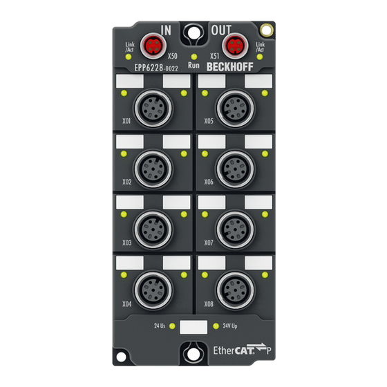
Product overview EPP2008-0022 3.3.1 Introduction Tx+ / GND Rx+ / GND EtherCAT P EtherCAT P Rx- / U input downstream connection Tx- / U +24 V U n.c. Output Digital n.c. outputs 8 digital outputs The EPP2008-0022 EtherCAT P Box with digital outputs connects binary control signals from the controller to the actuators at the process level. -
Page 18: Technical Data
Product overview 3.3.2 Technical data All values are typical values over the entire temperature range, unless stated otherwise. EtherCAT P Connection 2 x M8 socket, 4-pin, P-coded, red Supply voltages Connection See EtherCAT P connection nominal voltage 24 V (-15 % / +20 %) sum current: I max. 3 A S,sum Current consumption from U 100 mA... -
Page 19: Scope Of Supply
Product overview Additional tests The devices have undergone the following additional tests: Test Explanation Vibration 10 frequency sweeps in 3 axes 5 Hz < f < 60 Hz displacement 0.35 mm, constant amplitude 60.1 Hz < f < 500 Hz acceleration 5 g, constant amplitude Shocks 1000 shocks in each direction, in 3 axes 35 g, 11 ms 3.3.3 Scope of supply... -
Page 20: Process Image
Product overview 3.3.4 Process image Process image in TwinCAT Connector Contact Output variable Channel 1 Output Channel 2 Output Channel 3 Output Channel 4 Output Channel 5 Output Channel 6 Output Channel 7 Output Channel 8 Output Version: 1.6 EPP2xxx... -
Page 21: Epp2028-000X
Product overview EPP2028-000x 3.4.1 Introduction EPP2028-0001 Tx+ / GND EtherCAT P EtherCAT P Rx+ / GND input downstream connection Rx- / U Tx- / U +24 V U Digital outputs Output EPP2028-0002 Tx+ / GND EtherCAT P EtherCAT P Rx+ / GND input downstream connection Rx- / U Tx- / U +24 V U... -
Page 22: Technical Data
Product overview 3.4.2 Technical data All values are typical values over the entire temperature range, unless stated otherwise. EtherCAT P Connection 2 x M8 socket, 4-pin, P-coded, red Supply voltages Connection See EtherCAT P connection nominal voltage 24 V (-15 % / +20 %) sum current: I max. 3 A S,sum Current consumption from U 100 mA... -
Page 23: Scope Of Supply
Product overview Additional tests The devices have undergone the following additional tests: Test Explanation Vibration 10 frequency sweeps in 3 axes 5 Hz < f < 60 Hz displacement 0.35 mm, constant amplitude 60.1 Hz < f < 500 Hz acceleration 5 g, constant amplitude Shocks 1000 shocks in each direction, in 3 axes 35 g, 11 ms 3.4.3 Scope of supply... -
Page 24: Process Image
Product overview 3.4.4 Process image EPP2028-0001 Process image in TwinCAT Connector Contact Output variable Channel 1 Output Channel 2 Output Channel 3 Output Channel 4 Output Channel 5 Output Channel 6 Output Channel 7 Output Channel 8 Output EPP2028-0002 Process image in TwinCAT Connector Contact Output variable... -
Page 25: Epp2038-000X
Product overview EPP2038-000x 3.5.1 Introduction EPP2038-0001 Tx+ / GND EtherCAT P EtherCAT P Rx+ / GND input downstream connection Rx- / U Tx- / U +24 V U Digital outputs Output EPP2038-0002 Tx+ / GND EtherCAT P EtherCAT P Rx+ / GND input downstream connection Rx- / U Tx- / U +24 V U... - Page 26 Product overview Quick links Technical data [} 27] Process image [} 29] Signal connection M8 [} 121] Signal connection M12 [} 122] Version: 1.6 EPP2xxx...
-
Page 27: Technical Data
Product overview 3.5.2 Technical data All values are typical values over the entire temperature range, unless stated otherwise. EtherCAT P Connection 2 x M8 socket, 4-pin, P-coded, red Supply voltages Connection See EtherCAT P connection nominal voltage 24 V (-15 % / +20 %) sum current: I max. 3 A S,sum Current consumption from U 100 mA... -
Page 28: Scope Of Supply
Product overview Additional tests The devices have undergone the following additional tests: Test Explanation Vibration 10 frequency sweeps in 3 axes 5 Hz < f < 60 Hz displacement 0.35 mm, constant amplitude 60.1 Hz < f < 500 Hz acceleration 5 g, constant amplitude Shocks 1000 shocks in each direction, in 3 axes 35 g, 11 ms 3.5.3 Scope of supply... -
Page 29: Process Image
Product overview 3.5.4 Process image EPP2038-0001 Process image in TwinCAT Connector Contact Output variable Diagnostic bit Channel 1 Diag Channel 1 Output Input Channel 2 Diag Channel 2 Output Input Channel 3 Diag Channel 3 Output Input Channel 4 Diag Channel 4 Output Input Channel 5... -
Page 30: Epp2308-000X, Epp2318-000X
Product overview EPP2308-000x, EPP2318-000x 3.6.1 Introduction EPP2308-0001, EPP2318-0001 Tx+ / GND EtherCAT P EtherCAT P Rx+ / GND input downstream connection Rx- / U Tx- / U Digital +24 V U inputs Input +24 V U Digital outputs Output EPP2308-0002, EPP2318-0002 Tx+ / GND EtherCAT P EtherCAT P Rx+ / GND... - Page 31 Product overview Digital inputs M12 [} 116] Digital outputs M8 [} 121] Digital outputs M12 [} 122] EPP2xxx Version: 1.6...
-
Page 32: Technical Data
Product overview 3.6.2 Technical data All values are typical values over the entire temperature range, unless stated otherwise. EtherCAT P Connection 2 x M8 socket, 4-pin, P-coded, red Supply voltages Connection See EtherCAT P connection nominal voltage 24 V (-15 % / +20 %) sum current: I max. 3 A S,sum Current consumption from U 100 mA... -
Page 33: Scope Of Supply
Product overview Environmental conditions Ambient temperature during operation -25 … +60 °C -25 … +55 °C according to cULus Ambient temperature during storage -40 … +85 °C Vibration resistance, shock resistance conforms to EN 60068-2-6 / EN 60068-2-27 Additional checks [} 33] EMC immunity / emission conforms to EN 61000-6-2 / EN 61000-6-4 Protection class IP65, IP66, IP67 (conforms to EN 60529) Approvals / markings... -
Page 34: Process Image
Product overview 3.6.4 Process image EPP2308-0001, EPP2318-0001 Process image in TwinCAT Connector Contact Variable Channel 1 Input Channel 2 Input Channel 3 Input Channel 4 Input Channel 5 Output Channel 6 Output Channel 7 Output Channel 8 Output EPP2308-0002, EPP2318-0002 Process image in TwinCAT Connector Contact... -
Page 35: Epp2328-000X
Product overview EPP2328-000x 3.7.1 Introduction EPP2328-0001 Tx+ / GND EtherCAT P EtherCAT P Rx+ / GND input downstream connection Rx- / U Tx- / U Digital +24 V U inputs Input +24 V U Digital outputs Output EPP2328-0002 Tx+ / GND EtherCAT P EtherCAT P Rx+ / GND input... - Page 36 Product overview Digital inputs M12 [} 116] Digital outputs M8 [} 121] Digital outputs M12 [} 122] Version: 1.6 EPP2xxx...
-
Page 37: Technical Data
Product overview 3.7.2 Technical data All values are typical values over the entire temperature range, unless stated otherwise. EtherCAT P Connection 2 x M8 socket, 4-pin, P-coded, red Supply voltages Connection See EtherCAT P connection nominal voltage 24 V (-15 % / +20 %) sum current: I max. 3 A S,sum Current consumption from U 100 mA... -
Page 38: Scope Of Supply
Product overview Environmental conditions Ambient temperature during operation -25 … +60 °C -25 … +55 °C according to cULus Ambient temperature during storage -40 … +85 °C Vibration resistance, shock resistance conforms to EN 60068-2-6 / EN 60068-2-27 Additional checks [} 38] EMC immunity / emission conforms to EN 61000-6-2 / EN 61000-6-4 Protection class IP65, IP66, IP67 (conforms to EN 60529) Approvals / markings... -
Page 39: Process Image
Product overview 3.7.4 Process image EPP2328-0001 Process image in TwinCAT Connector Contact Variable Channel 1 Input Channel 2 Input Channel 3 Input Channel 4 Input Channel 5 Output Channel 6 Output Channel 7 Output Channel 8 Output EPP2328-0002 Process image in TwinCAT Connector Contact Variable... -
Page 40: Epp2316-000X
Product overview EPP2316-000x 3.8.1 Introduction EPP2316-0003 Tx+ / GND EtherCAT P EtherCAT P Rx+ / GND Rx- / U input downstream connection Tx- / U Input 1 Input 2 Input 3 Input 4 Digital inputs Input 5 Input 6 Input 7 Input 8 1-wire 2-wire... - Page 41 Product overview Quick links Technical data [} 42] Process image [} 44] ZS2001 digital inputs [} 117] Digital inputs D-sub 25 [} 119] ZS2001 digital outputs [} 127] Digital outputs D-sub 25 [} 125] EPP2xxx Version: 1.6...
-
Page 42: Technical Data
Product overview 3.8.2 Technical data All values are typical values over the entire temperature range, unless stated otherwise. EtherCAT P Connection 2 x M8 socket, 4-pin, P-coded, red Supply voltages Connection See EtherCAT P connection nominal voltage 24 V (-15 % / +20 %) sum current: I max. 3 A S,sum Current consumption from U 100 mA... -
Page 43: Scope Of Supply
Product overview Housing data Dimensions W x H x D 30 mm x 126 mm x 26.5 mm (without connectors) Weight approx. 165 g Installation position variable Material PA6 (polyamide) Technical data EPP2316-0003 EPP2316-0008 Ambient temperature during operation -25 … +60 °C -25 … +60 °C -25 … +55 °C according to cULus Ambient temperature during storage -40 … +85 °C Vibration / shock resistance conforms to EN 60068-2-6 / EN 60068-2-27;... -
Page 44: Process Image
Product overview 3.8.4 Process image EPP2316-0003 Process image in TwinCAT Connector Contact Variable Diagnostic bit DIG Inputs Input 1 DIG Inputs Input 2 DIG Inputs Input 3 DIG Inputs Input 4 DIG Inputs Input 5 DIG Inputs Input 6 DIG Inputs Input 7 DIG Inputs Input 8... - Page 45 Product overview EPP2316-0008 Process image in TwinCAT Connector Contact Variable Diagnostic bit DIG Inputs Input 1 DIG Inputs Input 2 DIG Inputs Input 3 DIG Inputs Input 4 DIG Inputs Input 5 DIG Inputs Input 6 DIG Inputs Input 7 DIG Inputs Input 8 DIG Outputs...
- Page 46 Pre-Operational (PRE-OP) and Operational (OP), but not in the network state INIT. Error channel X Indicates an error on channel X. Sync Error See EtherCAT system documentation. The EtherCAT system documentation is available on the Beckhoff homepage under Downloads. TxPDO Toggle See EtherCAT system documentation. Version: 1.6...
-
Page 47: Status Leds
Product overview DIG Outputs Device You will find the module's control outputs under DIG Outputs Device. Fig. 2: EPP2316-0008, DIG Outputs Device Set safe state Sets the module to the safe state. Reset outputs Resets the error bits "Error channel X" of the module. The outputs are reactivated. 3.8.5 Status LEDs Fig. 3: EPP2316-0008 - Status LEDs... -
Page 48: Epp2334-0061
Product overview EPP2334-0061 3.9.1 Introduction Tx+ / GND EtherCAT P EtherCAT P Rx+ / GND input downstream connection Rx- / U Tx- / U Digital +24 V U inputs/outputs In-/Output Combined digital inputs and outputs The EPP2334-0061 EtherCAT P Box has four digital channels, which can each be operated as an input or output. -
Page 49: Technical Data
Product overview 3.9.2 Technical data All values are typical values over the entire temperature range, unless stated otherwise. EtherCAT P Connection 2 x M8 socket, 4-pin, P-coded, red Supply voltages Connection See EtherCAT P connection nominal voltage 24 V (-15 % / +20 %) sum current: I max. 3 A S,sum Current consumption from U 100 mA... -
Page 50: Scope Of Supply
Product overview Environmental conditions Ambient temperature during operation -25 … +60 °C -25 … +55 °C according to cULus Ambient temperature during storage -40 … +85 °C Vibration resistance, shock resistance conforms to EN 60068-2-6 / EN 60068-2-27 Additional checks [} 50] EMC immunity / emission conforms to EN 61000-6-2 / EN 61000-6-4 Protection class IP65, IP66, IP67 (conforms to EN 60529) Approvals / markings... -
Page 51: Process Image
Product overview 3.9.4 Process image Process image in TwinCAT Connector Contact Input variable Output variable Channel 1 Channel 5 Input Output Channel 2 Channel 6 Input Output Channel 3 Channel 7 Input Output Channel 4 Channel 8 Input Output EPP2xxx Version: 1.6... -
Page 52: Epp2338-000X
Product overview 3.10 EPP2338-000x 3.10.1 Introduction EPP2338-0001 Tx+ / GND EtherCAT P EtherCAT P Rx+ / GND input downstream connection Rx- / U Tx- / U +24 V U Digital inputs/outputs In-/Output EPP2338-0002 Tx+ / GND EtherCAT P EtherCAT P Rx+ / GND input downstream connection Rx- / U Tx- / U... - Page 53 Product overview Supply of the connected sensors from U , not from U In contrast to many other modules, the EPP2338-000x EtherCAT P Box modules supply digital sen- sors from the peripheral voltage U , rather than from the control voltage U .
-
Page 54: Technical Data
Product overview 3.10.2 Technical data All values are typical values over the entire temperature range, unless stated otherwise. EtherCAT P Connection 2 x M8 socket, 4-pin, P-coded, red Supply voltages Connection See EtherCAT P connection nominal voltage 24 V (-15 % / +20 %) sum current: I max. 3 A S,sum Current consumption from U 100 mA... -
Page 55: Scope Of Supply
Product overview Environmental conditions Ambient temperature during operation -25 … +60 °C -25 … +55 °C according to cULus Ambient temperature during storage -40 … +85 °C Vibration resistance, shock resistance conforms to EN 60068-2-6 / EN 60068-2-27 Additional checks [} 55] EMC immunity / emission conforms to EN 61000-6-2 / EN 61000-6-4 Protection class IP65, IP66, IP67 (conforms to EN 60529) Approvals / markings... -
Page 56: Process Image
Product overview 3.10.4 Process image EPP2338-0001 Process image in TwinCAT Connector Contact Input variable Output variable Channel 1 Channel 9 Input Output Channel 2 Channel 10 Input Output Channel 3 Channel 11 Input Output Channel 4 Channel 12 Input Output Channel 5 Channel 13 Input... -
Page 57: Epp2338-X100
Product overview 3.11 EPP2338-x100 3.11.1 Introduction EPP2338-1001 Tx+ / GND EtherCAT P EtherCAT P Rx+ / GND input downstream connection Rx- / U Tx- / U +24 V U Digital inputs/outputs In-/Output EPP2338-1002 Tx+ / GND EtherCAT P EtherCAT P Rx+ / GND input downstream connection Rx- / U Tx- / U... - Page 58 Product overview Supply of the connected sensors from U , not from U In contrast to many other modules, the EPP2338-100x EtherCAT P Box modules supply digital sen- sors from the peripheral voltage U , rather than from the control voltage U .
-
Page 59: Technical Data
Product overview 3.11.2 Technical data All values are typical values over the entire temperature range, unless stated otherwise. EtherCAT P Connection 2 x M8 socket, 4-pin, P-coded, red Supply voltages Connection See EtherCAT P connection nominal voltage 24 V (-15 % / +20 %) sum current: I max. 3 A S,sum Current consumption from U 100 mA... -
Page 60: Scope Of Supply
Product overview Environmental conditions Ambient temperature during operation -25 … +60 °C -25 … +55 °C according to cULus Ambient temperature during storage -40 … +85 °C Vibration resistance, shock resistance conforms to EN 60068-2-6 / EN 60068-2-27 Additional checks [} 60] EMC immunity / emission conforms to EN 61000-6-2 / EN 61000-6-4 Protection class IP65, IP66, IP67 (conforms to EN 60529) Approvals / markings... -
Page 61: Process Image
Product overview 3.11.4 Process image EPP2338-1001 Process image in TwinCAT Connector Contact Input variable Output variable Channel 1 Channel 9 Input Output Channel 2 Channel 10 Input Output Channel 3 Channel 11 Input Output Channel 4 Channel 12 Input Output Channel 5 Channel 13 Input... -
Page 62: Epp2338-2002
Product overview 3.12 EPP2338-2002 3.12.1 Introduction Tx+ / GND EtherCAT P EtherCAT P Rx+ / GND input downstream connection Rx- / U Tx- / U +24 V U In-/Output B Digital In-/Output A inputs/outputs n.c. Combined digital inputs and outputs The EPP2338-2002 EtherCAT P Box has eight digital channels, which can each be operated as an input or output. -
Page 63: Technical Data
Product overview 3.12.2 Technical data All values are typical values over the entire temperature range, unless stated otherwise. EtherCAT P Connection 2 x M8 socket, 4-pin, P-coded, red Supply voltages Connection See EtherCAT P connection nominal voltage 24 V (-15 % / +20 %) sum current: I max. 3 A S,sum Current consumption from U 100 mA... -
Page 64: Scope Of Supply
Product overview Environmental conditions Ambient temperature during operation -25 … +60 °C -25 … +55 °C according to cULus Ambient temperature during storage -40 … +85 °C Vibration resistance, shock resistance conforms to EN 60068-2-6 / EN 60068-2-27 Additional checks [} 64] EMC immunity / emission conforms to EN 61000-6-2 / EN 61000-6-4 Protection class IP65, IP66, IP67 (conforms to EN 60529) Approvals / markings... -
Page 65: Process Image
Product overview 3.12.4 Process image EPP2338-x001 Process image in TwinCAT Connector Contact Input variable Output variable Channel 1 Channel 9 Input Output Channel 2 Channel 10 Input Output Channel 3 Channel 11 Input Output Channel 4 Channel 12 Input Output Channel 5 Channel 13 Input... -
Page 66: Epp2339-0003
Product overview 3.13 EPP2339-0003 3.13.1 Introduction Tx+ / GND EtherCAT P EtherCAT P Rx+ / GND input downstream connection Rx- / U Tx- / U +24 V U In-/Output 1 In-/Output 2 In-/Output 3 Digital In-/Output 4 inputs/outputs In-/Output 5 In-/Output 6 In-/Output 7 In-/Output 8 16-channel digital input or output 24 V... -
Page 67: Technical Data
Product overview 3.13.2 Technical data All values are typical values over the entire temperature range, unless stated otherwise. EtherCAT P Connection 2 x M8 socket, 4-pin, P-coded, red Supply voltages Connection See EtherCAT P connection nominal voltage 24 V (-15 % / +20 %) sum current: I max. 3 A S,sum Current consumption from U 100 mA... -
Page 68: Scope Of Supply
Product overview Environmental conditions Ambient temperature during operation -25…+60 °C Ambient temperature during storage -40 … +85 °C Vibration / shock resistance conforms to EN 60068-2-6 / EN 60068-2-27 EMC immunity / emission conforms to EN 61000-6-2 / EN 61000-6-4 Protection rating IP20 Approvals/markings Approvals/markings *) Real applicable approvals/markings see type plate on the side (product marking). Additional tests The devices have undergone the following additional tests: Test... -
Page 69: Process Image
Product overview 3.13.4 Process image Process image in TwinCAT Connec- Con- Input variable Output variable tact DI Inputs Channel 1 DO Outputs Channel 1 Input 1 Output 1 DI Inputs Channel 1 DO Outputs Channel 1 Input 2 Output 2 DI Inputs Channel 1 DO Outputs Channel 1 Input 3... -
Page 70: Epp2339-002X, Epp2349-002X
Product overview 3.14 EPP2339-002x, EPP2349-002x 3.14.1 Introduction EPP2339-0021, EPP2349-0021 Tx+ / GND Rx+ / GND EtherCAT P EtherCAT P Rx- / U input downstream connection Tx- / U +24 V U Digital In-/Output inputs/outputs EPP2339-0022, EPP2349-0022 Tx+ / GND Rx+ / GND EtherCAT P EtherCAT P Rx- / U... - Page 71 Product overview The signal state is indicated by means of LEDs. Sensors are supplied from the peripheral voltage U Quick links Technical data [} 72] Process image [} 74] Signal connection M8 [} 129] Signal connection M12 [} 130] EPP2xxx Version: 1.6...
-
Page 72: Technical Data
Product overview 3.14.2 Technical data All values are typical values over the entire temperature range, unless stated otherwise. EtherCAT P Connection 2 x M8 socket, 4-pin, P-coded, red Supply voltages Connection See EtherCAT P connection nominal voltage 24 V (-15 % / +20 %) sum current: I max. 3 A S,sum Current consumption from U 100 mA... -
Page 73: Scope Of Supply
Product overview Environmental conditions Ambient temperature during operation -25 … +60 °C -25 … +55 °C according to cULus Ambient temperature during storage -40 … +85 °C Vibration resistance, shock resistance conforms to EN 60068-2-6 / EN 60068-2-27 Additional checks [} 73] EMC immunity / emission conforms to EN 61000-6-2 / EN 61000-6-4 Protection class IP65, IP66, IP67 (conforms to EN 60529) Approvals / markings... -
Page 74: Process Image
Product overview 3.14.4 Process image EPP23x9-0021 Process image in TwinCAT Connector Contact Input variable Output variable Channel 1 Channel 17 Input Output Channel 2 Channel 18 Input Output Channel 3 Channel 19 Input Output Channel 4 Channel 20 Input Output Channel 5 Channel 21 Input... - Page 75 Product overview EPP23x9-0022 Process image in TwinCAT Connector Contact Input variable Output variable X01 / X02 Channel 2 Channel 18 Input Output Channel 1 Channel 17 Input Output X03 / X04 Channel 4 Channel 20 Input Output Channel 3 Channel 19 Input Output X05 / X06...
-
Page 76: Epp2624-0002
Product overview 3.15 EPP2624-0002 3.15.1 Introduction Tx+ / GND EtherCAT P EtherCAT P Rx+ / GND input downstream connection Rx- / U Tx- / U +24 V U Relay outputs n.c. 4 potential-free relay outputs The EPP2624-0002 EtherCAT P Box has four relays, each with a single contact. The relay contact can be used up to 25 V or 30 V . -
Page 77: Technical Data
Product overview 3.15.2 Technical data All values are typical values over the entire temperature range, unless stated otherwise. EtherCAT P Connection 2 x M8 socket, 4-pin, P-coded, red Supply voltages Connection See EtherCAT P connection nominal voltage 24 V (-15 % / +20 %) sum current: I max. 3 A S,sum Current consumption from U 100 mA... -
Page 78: Scope Of Supply
Product overview Test Explanation Vibration 10 frequency sweeps in 3 axes 5 Hz < f < 60 Hz displacement 0.35 mm, constant amplitude 60.1 Hz < f < 500 Hz acceleration 5 g, constant amplitude Shocks 1000 shocks in each direction, in 3 axes 35 g, 11 ms 3.15.3 Scope of supply Make sure that the following components are included in the scope of delivery: •... -
Page 79: Process Image
Product overview 3.15.4 Process image Process image in TwinCAT Connector Contact Output variable 2 , 4 Channel 1 Output 2 , 4 Channel 2 Output 2 , 4 Channel 3 Output 2 , 4 Channel 4 Output EPP2xxx Version: 1.6... -
Page 80: Epp2809-002X
Product overview 3.16 EPP2809-002x 3.16.1 Introduction EPP2809-0021 Tx+ / GND Rx+ / GND EtherCAT P EtherCAT P Rx- / U input downstream connection Tx- / U +24 V U Digital Output outputs EPP2809-0022 Tx+ / GND Rx+ / GND EtherCAT P EtherCAT P Rx- / U input... - Page 81 Product overview Quick links Technical data [} 82] Process image [} 84] Signal connection M8 [} 129] Signal connection M12 [} 130] EPP2xxx Version: 1.6...
-
Page 82: Technical Data
Product overview 3.16.2 Technical data All values are typical values over the entire temperature range, unless stated otherwise. EtherCAT P Connection 2 x M8 socket, 4-pin, P-coded, red Supply voltages Connection See EtherCAT P connection nominal voltage 24 V (-15 % / +20 %) sum current: I max. 3 A S,sum Current consumption from U 100 mA... -
Page 83: Scope Of Supply
Product overview Additional tests The devices have undergone the following additional tests: Test Explanation Vibration 10 frequency sweeps in 3 axes 5 Hz < f < 60 Hz displacement 0.35 mm, constant amplitude 60.1 Hz < f < 500 Hz acceleration 5 g, constant amplitude Shocks 1000 shocks in each direction, in 3 axes 35 g, 11 ms 3.16.3 Scope of supply... -
Page 84: Process Image
Product overview 3.16.4 Process image EPP2809-0021 Process image in TwinCAT Connector Contact Output variable Channel 1 Output Channel 2 Output Channel 3 Output Channel 4 Output Channel 5 Output Channel 6 Output Channel 7 Output Channel 8 Output Channel 9 Output Channel 10 Output... - Page 85 Product overview EPP2809-0022 Process image in TwinCAT Connector Contact Output variable X01 / X02 Channel 2 Output Channel 1 Output X03 / X04 Channel 4 Output Channel 3 Output X05 / X06 Channel 6 Output Channel 5 Output X07 / X08 Channel 8 Output Channel 7...
-
Page 86: Epp2816-0004
Product overview 3.17 EPP2816-0004 3.17.1 Introduction Tx+ / GND EtherCAT P EtherCAT P Rx+ / GND input downstream connection Rx- / U Tx- / U A … L | Output 1 … 11 N … S | Output 12 … 16 Digital outputs | n.c. -
Page 87: Technical Data
Product overview 3.17.2 Technical data All values are typical values over the entire temperature range, unless stated otherwise. EtherCAT P Connection 2 x M8 socket, 4-pin, P-coded, red Distributed Clocks Supply voltages Connection See EtherCAT P connection nominal voltage 24 V (-15 % / +20 %) sum current: I max. -
Page 88: Scope Of Supply
Product overview Test Explanation Vibration 10 frequency sweeps in 3 axes 5 Hz < f < 60 Hz displacement 0.35 mm, constant amplitude 60.1 Hz < f < 500 Hz acceleration 5 g, constant amplitude Shocks 1000 shocks in each direction, in 3 axes 35 g, 11 ms 3.17.3 Scope of supply Make sure that the following components are included in the scope of delivery: •... -
Page 89: Process Image
Product overview 3.17.4 Process image Process image in TwinCAT Connector Contact Output variable Diagnostic bit DIG Outputs Channel 1 DIG Diag Inputs Channel 1 Output 1 Diag Input 1 DIG Outputs Channel 1 DIG Diag Inputs Channel 1 Output 2 Diag Input 2 DIG Outputs Channel 1 DIG Diag Inputs Channel 1... -
Page 90: Epp2816-0008
Product overview 3.18 EPP2816-0008 3.18.1 Introduction Tx+ / GND EtherCAT P EtherCAT P Rx+ / GND input downstream connection Rx- / U Tx- / U 1 … 16 | Output 1 … 16 17 … 22 | +24 V U Digital outputs 23 …... -
Page 91: Technical Data
Product overview 3.18.2 Technical data All values are typical values over the entire temperature range, unless stated otherwise. EtherCAT P Connection 2 x M8 socket, 4-pin, P-coded, red Distributed Clocks Supply voltages Connection See EtherCAT P connection nominal voltage 24 V (-15 % / +20 %) sum current: I max. -
Page 92: Scope Of Supply
Product overview Additional tests The devices have undergone the following additional tests: Test Explanation Vibration 10 frequency sweeps in 3 axes 5 Hz < f < 60 Hz displacement 0.35 mm, constant amplitude 60.1 Hz < f < 500 Hz acceleration 5 g, constant amplitude Shocks 1000 shocks in each direction, in 3 axes 35 g, 11 ms 3.18.3 Scope of supply... -
Page 93: Process Image
Product overview 3.18.4 Process image Process image in TwinCAT Connector Contact Output variable Diagnostic bit DIG Outputs Channel 1 DIG Diag Inputs Channel 1 Output 1 Diag Input 1 DIG Outputs Channel 1 DIG Diag Inputs Channel 1 Output 2 Diag Input 2 DIG Outputs Channel 1 DIG Diag Inputs Channel 1... - Page 94 Pre-Operational (PRE-OP) and Operational (OP), but not in the network state INIT. Error channel X Indicates an error on channel X. Sync Error See EtherCAT system documentation. The EtherCAT system documentation is available on the Beckhoff homepage under Downloads. TxPDO Toggle See EtherCAT system documentation. Version: 1.6...
-
Page 95: Status Leds
Product overview DIG Outputs Device You will find the module's control outputs under DIG Outputs Device. Fig. 5: EPP2816-0008, DIG Outputs Device Set safe state Sets the module to the safe state. Reset outputs Resets the error bits "Error channel X" of the module. The outputs are reactivated. 3.18.5 Status LEDs Fig. 6: EPP2816-0008 - Status LEDs... -
Page 96: Epp2816-0010
Product overview 3.19 EPP2816-0010 3.19.1 Introduction Tx+ / GND EtherCAT P EtherCAT P Rx+ / GND input downstream connection Rx- / U Tx- / U 1 … 8 | Output | GND Digital outputs Digital output The EPP2816-0010 EtherCAT P Box is designed for processing digital/binary signals. It connects the binary control signals from the automation device on to the actuators at the process level. -
Page 97: Technical Data
Product overview 3.19.2 Technical data All values are typical values over the entire temperature range, unless stated otherwise. EtherCAT P Connection 2 x M8 socket, 4-pin, P-coded, red Distributed Clocks Supply voltages Connection See EtherCAT P connection nominal voltage 24 V (-15 % / +20 %) sum current: I max. -
Page 98: Scope Of Supply
Product overview Test Explanation Vibration 10 frequency sweeps in 3 axes 5 Hz < f < 60 Hz displacement 0.35 mm, constant amplitude 60.1 Hz < f < 500 Hz acceleration 5 g, constant amplitude Shocks 1000 shocks in each direction, in 3 axes 35 g, 11 ms 3.19.3 Scope of supply Make sure that the following components are included in the scope of delivery: •... -
Page 99: Process Image
Product overview 3.19.4 Process image Process image in TwinCAT Connector Contact Output variable Diagnostic bit DIG Outputs Channel 1 DIG Diag Inputs Channel 1 Output 1 Diag Input 1 DIG Outputs Channel 1 DIG Diag Inputs Channel 1 Output 2 Diag Input 2 DIG Outputs Channel 1 DIG Diag Inputs Channel 1... -
Page 100: Epp2817-0008
Product overview 3.20 EPP2817-0008 3.20.1 Introduction Tx+ / GND EtherCAT P EtherCAT P Rx+ / GND input downstream connection Rx- / U Tx- / U 1 … 12 | Output | GND Digital outputs 14 … 25 | Output Digital output The EPP2817-0008 EtherCAT P Box is designed for processing digital/binary signals. It connects the binary control signals from the automation device on to the actuators at the process level. -
Page 101: Technical Data
Product overview 3.20.2 Technical data All values are typical values over the entire temperature range, unless stated otherwise. EtherCAT P Connection 2 x M8 socket, 4-pin, P-coded, red Distributed Clocks Supply voltages Connection See EtherCAT P connection nominal voltage 24 V (-15 % / +20 %) sum current: I max. -
Page 102: Scope Of Supply
Product overview Additional tests The devices have undergone the following additional tests: Test Explanation Vibration 10 frequency sweeps in 3 axes 5 Hz < f < 60 Hz displacement 0.35 mm, constant amplitude 60.1 Hz < f < 500 Hz acceleration 5 g, constant amplitude Shocks 1000 shocks in each direction, in 3 axes 35 g, 11 ms 3.20.3 Scope of supply... -
Page 103: Process Image
Product overview 3.20.4 Process image Process image in TwinCAT Connector Contact Output variable Diagnostic bit DIG Output Channel 1 DIG Diag Inputs Channel 1 Output 1 Diag Input 1 DIG Output Channel 1 DIG Diag Inputs Channel 1 Output 3 Diag Input 3 DIG Output Channel 1 DIG Diag Inputs Channel 1... - Page 104 Product overview DIG Output Channel 2 DIG Diag Inputs Channel 2 Output 4 Diag Input 4 DIG Output Channel 2 DIG Diag Inputs Channel 2 Output 6 Diag Input 6 DIG Output Channel 2 DIG Diag Inputs Channel 2 Output 8 Diag Input 8 DIG Output Channel 3 DIG Diag Inputs Channel 3...
-
Page 105: Mounting And Cabling
Mounting and cabling Mounting and cabling Mounting 4.1.1 Dimensions Housing -000x and -0010 26.5 Ø 3.5 13.5 All dimensions are given in millimeters. The drawing is not true to scale. Housing features Housing material PA6 (polyamide) Sealing compound polyurethane Mounting two mounting holes Ø... - Page 106 Mounting and cabling Housing -002x 26.5 Ø 4.5 All dimensions are given in millimeters. The drawing is not true to scale. Housing features Housing material PA6 (polyamide) Sealing compound polyurethane Mounting two mounting holes Ø 4.5 mm for M4 Metal parts brass, nickel-plated Contacts CuZn, gold-plated...
- Page 107 Mounting and cabling Housing -0061 Ø 3.5 Ø 3.5 All dimensions are given in millimeters. The drawing is not true to scale. Housing features Housing material PA6 (polyamide) Sealing compound polyurethane Mounting two mounting holes Ø 3.5 mm for M3 Metal parts brass, nickel-plated Contacts...
-
Page 108: Fixing
Mounting and cabling 4.1.2 Fixing Protection of connectors against contamination! While mounting the modules, protect all connectors, against contamination! Only with connected ca- bles or plugs the protection class IP67 is guaranteed! Unused connectors have to be protected with the right plugs! See for plug sets in the catalogue. Modules with narrow housing are mounted with two M3 bolts. -
Page 109: Functional Earth (Fe)
Fig. 9: Connection for functional earth (FE) 4.1.4 Tightening torques for plug connectors Screw connectors tight with a torque wrench. (e.g. ZB8801 from Beckhoff) Connector diameter Tightening torque 0.4 Nm 0.6 Nm... -
Page 110: Ethercat P
Mounting and cabling EtherCAT P WARNING Power supply from SELV/PELV power supply unit! SELV/PELV circuits (Safety Extra Low Voltage, Protective Extra Low Voltage) according to IEC 61010-2-201 must be used to supply the EtherCAT P Power Sourcing Device (PSD). Notes: • SELV/PELV circuits may give rise to further requirements from standards such as IEC 60204-1 et al, for example with regard to cable spacing and insulation. -
Page 111: Connectors
Core color Tx + yellow Rx + white Rx - : peripheral voltage, +24 V blue Tx - : control voltage, +24 V orange Housing Shield Shield Shield The core colors apply to EtherCAT P cables and ECP cables from Beckhoff. EPP2xxx Version: 1.6... -
Page 112: Status Leds
Mounting and cabling 4.2.2 Status LEDs 4.2.2.1 Supply voltage EtherCAT P Box modules indicate the status of the supply voltages via two status LEDs. The status LEDs are labeled with the designations of the supply voltages: Us and Up. Display Meaning not present. green illuminated present. -
Page 113: Conductor Losses
Mounting and cabling 4.2.3 Conductor losses Take into account the voltage drop on the supply line when planning a system. Avoid the voltage drop being so high that the supply voltage at the box lies below the minimum nominal voltage. Variations in the voltage of the power supply unit must also be taken into account. -
Page 114: Supply And Connection Of Sensor/Actuator To Epp Boxes
Mounting and cabling Supply and connection of sensor/actuator to EPP boxes NOTE Supply and connection of sensors and actuators to EtherCAT P Box modules The connected sensors and actuators must be supplied by an EtherCAT P Box. GND and GND from one of the M8 / M12 signal connections of an EtherCAT P Box must not be connected to the machine bed. Supply of externally powered sensors or actuators If the sensors and actuators cannot be supplied from the EtherCAT P Box, the supply of externally powered sensors and actuators must be electrically isolated. -
Page 115: Digital Inputs
Mounting and cabling Digital inputs 4.4.1 Digital inputs M8 Fig. 12: M8 socket, 3-pin Symbol Description +24 V Us Sensor supply: 24 V from U Input Digital input Use the output voltage at pin 1 as supply voltage for sensors. Make sure that the sum of the supply currents of all connected sensors does not exceed the sum current of 0.5 A. -
Page 116: Digital Inputs M12
Mounting and cabling 4.4.2 Digital inputs M12 Fig. 13: M12 socket, 5-pin Symbol Description +24 V Us Sensor supply: 24 V from U Input B Digital input Input A Digital input n.c. Use the output voltage at pin 1 as supply voltage for sensors. Make sure that the sum of the supply currents of all connected sensors does not exceed the sum current of 0.5 A. -
Page 117: Zs2001 Digital Inputs
Mounting and cabling 4.4.3 ZS2001 digital inputs GNDs GNDs GNDs GNDs EPP2316-0003 ... with ZS2001-0001 ... with ZS2001-0002 ... with ZS2001-0004 The ZS2001 connectors are not included in the scope of delivery. See chapter Accessories [} 144]. NOTE Different pin numbering GNDp GNDp GNDp... - Page 118 Mounting and cabling Connection examples ZS2001-0001 ZS2001-0004 ZS2001-0002 The diagram shows the connection of 8 sensors in single-wire technology and one sensor each in two-wire and three-wire technology. Please note for connector ZS2001-0004: two bridges (24 V and 0 V) are required to supply the terminal points for two-wire and three-wire connection technology.
-
Page 119: Digital Inputs D-Sub 25
Mounting and cabling 4.4.4 Digital inputs D-sub 25 Fig. 14: D-sub socket, 25-pin EPP2316-0008 Input 1 Input 2 Input 3 Input 4 Input 5 Input 6 Input 7 Input 8 Output 1 Output 2 Output 3 Output 4 Output 5 Output 6 Output 7 Output 8 EPP2xxx... - Page 120 Mounting and cabling Connection example for EPP2316-0008 Version: 1.6 EPP2xxx...
-
Page 121: Digital Outputs
Mounting and cabling Digital outputs 4.5.1 Digital outputs M8 Fig. 15: M8 socket, 3-pin Symbol Description +24 V Up Auxiliary voltage output: 24 V from U GNDp Output Digital output The outputs are short-circuit proof and protected against inverse connection. LEDs indicate the signal state of the outputs. Connection examples Output Pin 4... -
Page 122: Digital Outputs M12
Mounting and cabling 4.5.2 Digital outputs M12 Fig. 16: M12 socket Symbol Description +24 V Up Auxiliary voltage output: 24 V from U Output B Digital output GNDp Output A Digital output n.c. The outputs are short-circuit proof and protected against inverse connection. LEDs indicate the signal state of the outputs. Connection examples Output B Pin 2... -
Page 123: M16 Sockets
Mounting and cabling 4.5.3 M16 sockets Pin assignment Description Channel 1, Output 1 Channel 1, Output 2 Channel 1, Output 3 Channel 1, Output 4 Channel 1, Output 5 Channel 1, Output 6 Channel 1, Output 7 Channel 1, Output 8 Channel 2, Output 1 Channel 2, Output 2 Channel 2, Output 3 Channel 2, Output 4 Channel 2, Output 5 Channel 2, Output 6 Channel 2, Output 7 Channel 2, Output 8 EPP2xxx Version: 1.6... -
Page 124: Digital Outputs D-Sub 9
Mounting and cabling 4.5.4 Digital outputs D-sub 9 Fig. 17: D-sub socket, 9-pin Description Output 1 Output 2 Output 3 Output 4 Output 5 Output 6 Output 7 Output 8 Version: 1.6 EPP2xxx... -
Page 125: Digital Outputs D-Sub 25
Mounting and cabling 4.5.5 Digital outputs D-sub 25 Fig. 18: D-sub socket, 25-pin EPP2316-0008 EPP2816-0008 EPP2817-0008 Input 1 Channel 1, Output 1 Channel 1, Output 1 Input 2 Channel 1, Output 2 Channel 1, Output 3 Input 3 Channel 1, Output 3 Channel 1, Output 5 Input 4 Channel 1, Output 4... - Page 126 Mounting and cabling 4.5.5.1 Connection examples EPP2316-0008 EPP2816-0008 Version: 1.6 EPP2xxx...
-
Page 127: Zs2001 Digital Outputs
Mounting and cabling 4.5.6 ZS2001 digital outputs GNDs GNDs GNDs GNDs GNDp GNDp GNDp GNDp EPP2316-0003 ... with ZS2001-0001 ... with ZS2001-0002 ... with ZS2001-0004 The ZS2001 connectors are not included in the scope of delivery. See chapter Accessories [} 144]. NOTE Different pin numbering Danger of confusion: The pins are numbered differently on the box than on the ZS2001. - Page 128 Mounting and cabling Connection examples ZS2001-0001 ZS2001-0004 ZS2002-0002 The diagram shows the connection of 8 actuators in 1-wire technique and one actuator each in 2-wire and 3- wire technique. Please note for connector ZS2001-0004: two bridges (24 V and 0 V) are required to supply the terminal points for 2-wire and 3-wire connection technology.
-
Page 129: Digital Inputs/Outputs
Mounting and cabling Digital inputs/outputs The EPP2334, EPP2338, EPP2339 and EPP2349 have digital channels which can be operated as inputs or outputs. If the channels are operated as digital inputs, the modules record the binary control signals from the process level and transport them to the higher-level automation device. -
Page 130: Digital Inputs/Outputs M12
Mounting and cabling 4.6.2 Digital inputs/outputs M12 Fig. 20: M12 socket, 5-pin EPP2338-0xxx EPP2338-2002 Description EPP2338-1xxx +24 V Up +24 V Us Sensor supply: 24 V Input/output B Input/output B Digital input or output Input/output A Input/output A Digital input or output n.c. n.c. Use the output voltage at pin 1 as supply voltage for sensors. -
Page 131: Digital Inputs/Outputs Zs2001
Mounting and cabling 4.6.3 Digital inputs/outputs ZS2001 GNDp GNDp GNDp GNDp GNDp GNDp GNDp GNDp EPP2339-0003 ... with 2x ZS2001-0001 ... with 2x ZS2001-0002 ... with 2x ZS2001-0004 The ZS2001 connectors are not included in the scope of delivery. See chapter Accessories [} 144]. NOTE Different pin numbering Danger of confusion: The pins are numbered differently on the box than on the ZS2001. - Page 132 Mounting and cabling ZS2001-0004 has three rows with ten terminal contacts each. The first row is occupied as shown in the table. The second and third rows are designed to distribute the supply voltage and ground. See connection examples [} 132]. Connection examples: Inputs ZS2001-0001 ZS2001-0004...
-
Page 133: Relay
Relay connection 14 black grey The core colors apply to M12 cables from Beckhoff: • ZK2000-5xxx • ZK2000-6xxx • ZK2000-7xxx Status LEDs There are two LEDs next to each M12 socket. The LED on the left turns green when the relay contact is closed. -
Page 134: Ul Requirements
Mounting and cabling UL Requirements The installation of the EtherCAT Box Modules certified by UL has to meet the following requirements. Supply voltage CAUTION CAUTION! This UL requirements are valid for all supply voltages of all marked EtherCAT Box Modules! For the compliance of the UL requirements the EtherCAT Box Modules should only be supplied •... -
Page 135: Disposal
Mounting and cabling Disposal Products marked with a crossed-out wheeled bin shall not be discarded with the normal waste stream. The device is considered as waste electrical and electronic equipment. The national regulations for the disposal of waste electrical and electronic equipment must be observed. EPP2xxx Version: 1.6... -
Page 136: Commissioning/Configuration
Commissioning/Configuration Commissioning/Configuration Integrating into a TwinCAT project The procedure for integration in a TwinCAT project is described in these Quick start guide. Version: 1.6 EPP2xxx... -
Page 137: Behavior Of The Outputs In Case Of A Fault (Epp2316 And Epp281X Only)
Commissioning/Configuration Behavior of the outputs in case of a fault (EPP2316 and EPP281x only) EPP2316 and EPP281x have diagnostic functions. They can detect faults and automatically react to them. The following chapters describe the configuration of the behavior in case of various types of fault. 5.2.1 Behavior in case of network failure You can use bit 8000:0n (Safe State Active) to specify whether channel n should assume a certain value... - Page 138 Commissioning/Configuration 8001:01 to 8001:08 - DIG Safe state value Ch.1, Output 1 to Output 8 (default: FALSE) Specifies what the safe state is. Value Meaning FALSE Output switched off TRUE Output switched on Version: 1.6 EPP2xxx...
-
Page 139: Behavior In Case Of Short Circuit
Commissioning/Configuration 5.2.2 Behavior in case of short circuit You can set the behavior of the outputs in case of short circuit in the CoE object F800 "DO Settings". F800:0 - DO Settings (Safe State Value) Table 1: F800:01 - Disable shut off (default: FALSE) Value Meaning FALSE... -
Page 140: Behavior In Case Of Lack Of Supply Voltage
Commissioning/Configuration 5.2.3 Behavior in case of lack of supply voltage The digital outputs are supplied from the supply voltage U . If the supply voltage U is not present, the digital outputs cannot output a high level. If an output is set and does not output a high level, this is detected as a fault. On expiry of the fault reaction time, the fault is reported in the process data: •... -
Page 141: Restore The Delivery State
Commissioning/Configuration Restore the delivery state You can restore the delivery state of the backup objects as follows: 1. Ensure that TwinCAT is running in Config mode. 2. In CoE object 1011:0 "Restore default parameters" select parameter 1011:01 "Subindex 001". 3. Double-click on "Subindex 001". ð... -
Page 142: Decommissioning
Commissioning/Configuration Decommissioning WARNING Risk of electric shock! Bring the bus system into a safe, de-energized state before starting disassembly of the devices! Version: 1.6 EPP2xxx... -
Page 143: Appendix
Appendix Appendix General operating conditions Protection degrees (IP-Code) The standard IEC 60529 (DIN EN 60529) defines the degrees of protection in different classes. 1. Number: dust protection and Definition touch guard Non-protected Protected against access to hazardous parts with the back of a hand. Protected against solid foreign objects of Ø 50 mm Protected against access to hazardous parts with a finger. -
Page 144: Accessories
Torque cable key for M12 / wrench size 13 for ZB8801-0000 ZB8801-0003 Torque cable key for M12 field assembly / wrench size 18 for ZB8801-0000 Further accessories Further accessories can be found in the price list for fieldbus components from Beckhoff and online at https://www.beckhoff.com. Version: 1.6 EPP2xxx... -
Page 145: Version Identification Of Ethercat Devices
Associated and synonymous with each revision there is usually a description (ESI, EtherCAT Slave Information) in the form of an XML file, which is available for download from the Beckhoff web site. From 2014/01 the revision is shown on the outside of the IP20 terminals, see Fig. “EL5021 EL terminal, standard IP20 IO device with batch number and revision ID (since 2014/01)”. -
Page 146: Version Identification Of Ep/Epi/Epp/Er/Eri Boxes
Version identification of EP/EPI/EPP/ER/ERI boxes The serial number/ data code for Beckhoff IO devices is usually the 8-digit number printed on the device or on a sticker. The serial number indicates the configuration in delivery state and therefore refers to a whole production batch, without distinguishing the individual modules of a batch. -
Page 147: Beckhoff Identification Code (Bic)
6.3.3 Beckhoff Identification Code (BIC) The Beckhoff Identification Code (BIC) is increasingly being applied to Beckhoff products to uniquely identify the product. The BIC is represented as a Data Matrix Code (DMC, code scheme ECC200), the content is based on the ANSI standard MH10.8.2-2016. - Page 148 Fig. 27: Example DMC 1P072222SBTNk4p562d71KEL1809 Q1 51S678294 An important component of the BIC is the Beckhoff Traceability Number (BTN, position 2). The BTN is a unique serial number consisting of eight characters that will replace all other serial number systems at Beckhoff in the long term (e.g.
-
Page 149: Electronic Access To The Bic (Ebic)
Electronic access to the BIC (eBIC) Electronic BIC (eBIC) The Beckhoff Identification Code (BIC) is applied to the outside of Beckhoff products in a visible place. If possible, it should also be electronically readable. Decisive for the electronic readout is the interface via which the product can be electronically addressed. - Page 150 Appendix ◦ The device must be in PREOP/SAFEOP/OP for access: ◦ the object 0x10E2 will be introduced into stock products in the course of a necessary firmware revision. ◦ From TwinCAT 3.1. build 4024.24 the functions FB_EcCoEReadBIC and FB_EcCoEReadBTN for reading into the PLC and further eBIC auxiliary functions are available in the Tc2_EtherCAT Library from v3.3.19.0.
-
Page 151: Support And Service
Please contact your Beckhoff branch office or representative for local support and service on Beckhoff products! The addresses of Beckhoff's branch offices and representatives round the world can be found on her internet pages: www.beckhoff.com You will also find further documentation for Beckhoff components there. - Page 153 Beckhoff Automation GmbH & Co. KG Hülshorstweg 20 33415 Verl Germany Phone: +49 5246 9630 info@beckhoff.com www.beckhoff.com...
Need help?
Do you have a question about the EPP2 Series and is the answer not in the manual?
Questions and answers