
Related Manuals for Beckhoff EP8309-1022


Summary of Contents for Beckhoff EP8309-1022
- Page 1 Documentation for EP8309-1022 Multi functional I/O Box Version: 2.0.0 Date: 2017-11-07...
-
Page 3: Table Of Contents
Object overview........................ 71 5.7.3 Object description and parameterization ................. 79 Restoring the delivery state ...................... 98 6 Diagnostics ............................ 100 7 Appendix .............................. 101 General operating conditions...................... 101 Firmware Update EL/ES/EM/EPxxxx.................. 102 7.2.1 Device description ESI file/XML .................. 103 7.2.2 Firmware explanation..................... 106 EP8309-1022 Version: 2.0.0... - Page 4 Table of contents 7.2.3 Updating controller firmware *.efw ................. 107 7.2.4 FPGA firmware *.rbf ....................... 108 7.2.5 Simultaneous updating of several EtherCAT devices ............ 112 EtherCAT Box- / EtherCAT P Box - Accessories................ 113 Support and Service ........................ 114 Version: 2.0.0 EP8309-1022...
-
Page 5: Foreword
The TwinCAT Technology is covered, including but not limited to the following patent applications and patents: EP0851348, US6167425 with corresponding applications or registrations in various other countries. ® EtherCAT is registered trademark and patented technology, licensed by Beckhoff Automation GmbH, Germany Copyright © Beckhoff Automation GmbH & Co. KG, Germany. -
Page 6: Safety Instructions
All the components are supplied in particular hardware and software configurations appropriate for the application. Modifications to hardware or software configurations other than those described in the documentation are not permitted, and nullify the liability of Beckhoff Automation GmbH & Co. KG. Personnel qualification This description is only intended for trained specialists in control, automation and drive engineering who are familiar with the applicable national standards. -
Page 7: Documentation Issue Status
FF - firmware version HH - hardware version Example with D-no.: 25 13 06 03: 25 - week of production 25 13 - year of production 2013 06 - firmware version 06 03 - hardware version 03 EP8309-1022 Version: 2.0.0... -
Page 8: Product Overview
• digital outputs with 0.5 or 2 A output current • analog inputs and outputs with 16 bit resolution • Thermocouple and RTD inputs • Stepper motor modules XFC (eXtreme Fast Control Technology) modules, including inputs with time stamp, are also available. Version: 2.0.0 EP8309-1022... -
Page 9: Fig. 2 Ethercat Box With M8 Connections For Sensors/Actuators
EtherCAT, which is available for download from our website (www.beckhoff.com) Note under Downloads. XML files You will find XML files (XML Device Description Files) for Beckhoff EtherCAT modules on our website (www.beckhoff.com) under Downloads, in the Configuration Files area. Note EP8309-1022... -
Page 10: Ep8309 - Introduction
A PWMi output is integrated for connecting a proportional valve. For valves with integrated electronics, this output can alternatively be operated as an analog current output with continuous 24V supply for the valve. Quick links • Installation [} 27] • Configuration [} 48] • UL requirements [} 44] Version: 2.0.0 EP8309-1022... -
Page 11: Ep8309 - Technical Data
0.5 A per channel for sockets 4 and 5 max. 1.0 A per channel for sockets 6 and 7 Short circuit current typically 1.5 A Output driver supply from load voltage Up Output driver current consumption typically 8 mA per channel EP8309-1022 Version: 2.0.0... - Page 12 Number of analog outputs (alternatively PWMi output) 1 M12 sockets Output connections [} 43] Signal type 0…20 mA or 4…20 mA (can be set for each CoE) Load < 500 Ω Resolution 12 bit Conversion time approx. 40 µs Measuring error < 0,3 % (relative to full scale value) Version: 2.0.0 EP8309-1022...
-
Page 13: Ep8309 - Process Image
1: value less than limit 2 (set in object 0x8000:14 [} 80]) 2: value greater than limit 2 (set in object 0x8000:14 [} 80]) 3: value equal to limit 2 (set in object 0x8000:14 [} 80]) Error: This bit is set if over- or under-range was detected. EP8309-1022 Version: 2.0.0... - Page 14 The diagnostic data for the two voltages Us and Up can be found under DEV Inputs. TRUE = voltage <= approx. 18 V ..TACHO Output Channel 1 The control data for the tacho input can be found under TACHO Output Channel 1. Reset Error - error reset Version: 2.0.0 EP8309-1022...
-
Page 15: Pulse Width Modulation (Pwm)
Analog Output - output value Pulse width modulation (PWM) The Beckhoff terminals and box modules integrate compact PWM output stages in the smallest of designs. PWM output stages control the output current through pulse width modulation (PWM) of the supply voltage. -
Page 16: Influencing Of The Pwmi Output Value By The Parameters
1 mH is not recommended, Note since the intermittent current flow prevents reference between the set value and the arith- metic mean of the current. Influencing of the PWMi output value by the parameters Fig. 7: Influencing of the PWMi output value Version: 2.0.0 EP8309-1022... -
Page 17: Basics Of Ethercat
The PDI watchdog can be used to monitor this communication for failure. The PDI watchdog monitors correct and timely process data communication with the ESC but from the application side. The SM and PDI watchdogs should be set separately for each slave in the TwinCAT System Manager: EP8309-1022 Version: 2.0.0... -
Page 18: Fig. 8 Ethercat Tab --> Advanced Settings --> Behavior --> Watchdog
1 to 65535, this covers a watchdog period of 0 to ~170 seconds. Calculation Multiplier = 2498 → watchdog base time = 1 / 25 MHz * (2498 + 2) = 0.0001 seconds = 100 µs SM watchdog = 10000 → 10000 * 100 µs = 1 second watchdog monitoring time Version: 2.0.0 EP8309-1022... - Page 19 (e.g. OFF), depending on the SAFEOP and OP settings, and depending on the device Note and its settings. If this is prevented due to deactivation of watchdog monitoring in the mod- ule, outputs can be switched or remain set in device state SAFEOP. EP8309-1022 Version: 2.0.0...
-
Page 20: Ethercat State Machine
Before it acknowledges the change of state, the EtherCAT slave copies current input data into the associated DP- RAM areas of the EtherCAT slave controller (ECSC). Version: 2.0.0 EP8309-1022... - Page 21 In the Boot state the slave firmware can be updated. The Boot state can only be reached via the Init state. In the Boot state mailbox communication via the file access over EtherCAT (FoE) protocol is possible, but no other mailbox communication and no process data communication. EP8309-1022 Version: 2.0.0...
-
Page 22: Coe Interface
CoE list. Note If a device has a CoE list, it is shown in the TwinCAT System Manager as a separate tab with a listing of the elements: Version: 2.0.0 EP8309-1022... -
Page 23: Fig. 10 Coe-Online Tab
Startup list Changes in the local CoE list of the terminal are lost if the terminal is replaced. If a termi- nal is replaced with a new Beckhoff terminal, it will have the factory settings. It is therefore Note advisable to link all changes in the CoE list of an EtherCAT slave with the Startup list of the slave, which is processed whenever the EtherCAT fieldbus is started. -
Page 24: Fig. 11 Startup List In The Twincat System Manager
• the offline list from the ESI file is displayed. In this case modifications are not meaningful or possible. • the configured status is shown under Identity • no firmware or hardware version is displayed, since these are features of the physical device. • Offline is shown in red Version: 2.0.0 EP8309-1022... -
Page 25: Fig. 12 Offline List
• the actual current slave directory is read. This may take several seconds, depending on the size and cycle time. • the actual identity is displayed • the firmware and hardware version of the equipment according to the electronic information is displayed. • Online is shown in green Fig. 13: Online list EP8309-1022 Version: 2.0.0... - Page 26 • Channel 1: parameter range x8010:00 ... x801F:255 • Channel 2: parameter range x8020:00 ... x802F:255 • … This is generally written as x80n0. Detailed information on the CoE interface can be found in the EtherCAT system documentation on the Beckhoff website. Version: 2.0.0 EP8309-1022...
-
Page 27: Mounting And Cabling
IP65, IP66, IP67 (conforms to EN 60529) when screwed together Dimensions (H x W x D) ca. 126 x 30 x 26,5 mm ca. 126 x 60 x 26,5 mm Weight approx. 125 g, depending on module type approx. 250 g, depending on module type EP8309-1022 Version: 2.0.0... -
Page 28: Fixing
The mounting rail ZS5300-0011 (500 mm x 129 mm) has in addition to the M3 treads also pre-made M4 treads to fix 60 mm wide modules via their middle holes. Up to 14 narrow or 7 wide modules may be mixed mounted. Version: 2.0.0 EP8309-1022... -
Page 29: Cabling
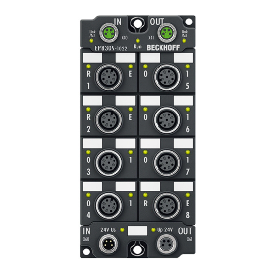
• digital In/Out channel 4 • digital In channel 2 / Tacho input 2 Socket 4: Socket 8: • digital In/Out channel 3 • pulse width current output • digital In/Out channel 4 • analog output Power In Power Out EP8309-1022 Version: 2.0.0... -
Page 30: Nut Torque For Connectors
ZB8800 is also a max. torque of 0.5 Nm permissible. Fig. 16: EtherCAT Box with M8 connectors M12 connectors It is recommended to pull the M12 connectors tight with a nut torque of 0.6 Nm. Fig. 17: EtherCAT Box with M8 and M12 connectors Version: 2.0.0 EP8309-1022... -
Page 31: Fig. 18 7/8" Plug Connectors
We recommend fastening the 7/8" plug connectors with a torque of 1.5 Nm. Fig. 18: 7/8" plug connectors Torque socket wrenches Fig. 19: ZB8801 torque socket wrench Ensure the right torque Use the torque socket wrenches available by Beckhoff to pull the connectors tight (ZB8800, ZB8801-0000)! Note EP8309-1022 Version: 2.0.0... -
Page 32: Ethercat
• the EtherCAT Box (EPxxxx) has two M8 sockets, marked in green • the Coupler Box (FBB-x110) has two M12 sockets Fig. 20: EtherCAT Box: M8 (30 mm housing) Fig. 21: EtherCAT Box: M8 60 mm housing (EP9214 for example ) Version: 2.0.0 EP8309-1022... -
Page 33: Fig. 22 Coupler Box: M12
M8 connectors were changed to the colors of EN61918 (yel- low, orange, white, blue).So different color coding exists. But the electrical properties are absolutely identical. EtherCAT connectors The following connectors can be supplied for use in Beckhoff EtherCAT systems. EP8309-1022 Version: 2.0.0... -
Page 34: Fig. 23 Ethercat-Leds
Status of the EtherCAT module is operational EtherCAT statuses The various statuses in which an EtherCAT module may be found are described in the Ba- sic System Documentation for EtherCAT, which is available for download from our website Note (www.beckhoff.com) under Downloads. Version: 2.0.0 EP8309-1022... -
Page 35: Power Connection
EtherCAT Box Modules! This can damage the modules! Attention Control voltage Us: 24 V Power is supplied to the fieldbus, the processor logic, the inputs and the sensors from the 24 V control voltage Us. The control voltage is electrically isolated from the fieldbus circuitry. EP8309-1022 Version: 2.0.0... - Page 36 Us and Up can thus easily be transferred from EtherCAT Box to EtherCAT Box. Pay attention to the maximum permissible current! Pay attention also for the redirection of the supply voltages Us and Up, the maximum per- missible current for M8 connectors of 4 A must not be exceeded! Attention Version: 2.0.0 EP8309-1022...
-
Page 37: Fig. 26 Ep92X4-0023, Connectors For Power In And Power Out
EP9214 or EP9224 (with integrated data logging, see www.beckhoff.com/EP9224) is recommended. With these modules intelligent power distribution concepts with up to 2 x 16 A and a maximum of 2.5 mm²... -
Page 38: Fig. 28 Status Leds For Power Supply
Because of overload (current > 0.5 A) the sensor supply generated from power supply voltage Us was switched off for all sensors fed from this. Up (Auxiliary voltage) The power supply voltage Up is not present green illuminated The power supply voltage Up is present Version: 2.0.0 EP8309-1022... -
Page 39: Fig. 29 Power Cable Conductor Losses
ZK2020-3334-0010 1.00 m ZK2020-3334-0020 2.00 m ZK2020-3334-0050 5.00 m Further available power cables and the associated data sheets can be found in the Beckhoff catalogue or on our website (http://www.beckhoff.de). Technical Data Data Rated voltage according to IEC61076-2-101 30 V Contamination level according to IEC 60 664-1 Insulation resistance IEC 60 512-2 >10... - Page 40 8 m power cable with 0.34 mm² cross-section has a voltage drop of 3.2 V at 4 A. EP92x4 Power Distribution Modules With EP9214 and EP9224 Power Distribution Modules intelligent concepts for voltage sup- ply are available. Further information may be found under www.beckhoff.com/EP9224. Note Version: 2.0.0...
-
Page 41: Signal Connection
The signals are connected via M12 connectors. Fig. 30: Digital inputs M12 The sensors are supplied with a common maximum current of 0.5 A from the control voltage Us. Light emitting diodes indicate the signal state of the inputs. EP8309-1022 Version: 2.0.0... -
Page 42: Fig. 31 Digital Inputs/Outputs M12
The analog signal inputs pick up analog control signals from the process level and transmit them to the higher-level automation device. The signals are connected via M12 connectors. Fig. 32: Analog inputs M12 The sensors are supplied with a common maximum current of 0.5 A from the control voltage Us. LEDs indicate the status of the inputs. Version: 2.0.0 EP8309-1022... -
Page 43: Fig. 33 Analog Output And Pwmi Output M12
Correct function is indicated if the green Run LED is on and the red Error LED is off. Status LEDs at the M12 connections Connection Display Meaning M12 socket digital left / Input / output off or Low inputs/outputs right green Input / output on or High EP8309-1022 Version: 2.0.0... -
Page 44: Ul Requirements
To meet the UL requirements, EtherCAT Box Modules has to be operated only at an ambi- ent temperature range of 0 to 55°C! CAUTION Marking for UL All EtherCAT Box Modules certified by UL (Underwriters Laboratories) are marked with the following label. Fig. 35: UL label Version: 2.0.0 EP8309-1022... -
Page 45: Commissioning And Configuration
Note elconfg.htm?id=1983920606140) and installed according to the installation instructions. At the Beckhoff TwinCAT System Manager the configuration tree can be build in two different ways: • by scanning [} 45] for existing hardware (called "online") and • by manual inserting/appending [} 45] of fieldbus devices, couplers and slaves. -
Page 46: Fig. 37 Appending A New I/O Device (I/O Devices -> Right-Click -> Append Device
Fig. 38: Selecting the device EtherCAT • Append a new box. Fig. 39: Appending a new box (Device -> right-click -> Append Box...) • In the dialog that appears select the desired box (e.g. EP2816-0008), and confirm with OK. Version: 2.0.0 EP8309-1022... -
Page 47: Fig. 40 Selecting A Box (E.g. Ep2816-0008)
Commissioning and Configuration Fig. 40: Selecting a Box (e.g. EP2816-0008) Fig. 41: Appended Box in the TwinCAT tree EP8309-1022 Version: 2.0.0... -
Page 48: Configuration Via Twincat
EtherCAT device type Comment Here you can add a comment (e.g. regarding the system). Disabled Here you can deactivate the EtherCAT device. Create symbols Access to this EtherCAT slave via ADS is only available if this checkbox is activated. Version: 2.0.0 EP8309-1022... -
Page 49: Fig. 44 Ethercat Tab
Indicates the configuration of the process data. The input and output data of the EtherCAT slave are represented as CANopen process data objects (PDO). The user can select a PDO via PDO assignment and modify the content of the individual PDO via this dialog, if the EtherCAT slave supports this function. EP8309-1022 Version: 2.0.0... - Page 50 (not selected and greyed out), this indicates that the input is excluded from the PDO assignment. In order to be able do select a greyed out PDO, the currently selected PDO has to be deselected first. Version: 2.0.0 EP8309-1022...
- Page 51 (CoE) or Servo drive over EtherCAT protocol. This tab indicates which download requests are sent to the mailbox during startup. It is also possible to add new mailbox requests to the list display. The download requests are sent to the slave in the same order as they are shown in the list. EP8309-1022 Version: 2.0.0...
- Page 52 (CoE) protocol. This dialog lists the content of the object directory of the slave (SDO upload) and enables the user to modify the content of an object from this list. Details for the objects of the individual EtherCAT devices can be found in the device-specific object descriptions. Version: 2.0.0 EP8309-1022...
- Page 53 The Update list button updates all objects in the displayed list Auto Update If this check box is selected, the content of the objects is updated automatically. Advanced The Advanced button opens the Advanced Settings dialog. Here you can specify which objects are displayed in the list. EP8309-1022 Version: 2.0.0...
- Page 54 Offline If this option button is selected, the list of the objects included in the object - via EDS file directory is read from an EDS file provided by the user. Online tab Fig. 49: Online tab Version: 2.0.0 EP8309-1022...
- Page 55 A carrier signal is available at the port, but the port is closed. File Access over EtherCAT Download With this button a file can be written to the EtherCAT device. Upload With this button a file can be read from the EtherCAT device. EP8309-1022 Version: 2.0.0...
-
Page 56: Tacho Analysis
The velocity is lower than the limit in CoE 0x8020:12 Rotational Speed Threshold or = 0 threshold Rotational Speed Rotational speed and frequency, shown as a function of CoE object 0x80x0:15 Rotation Direction 0: rising edge of input A occurs before rising edge of input B Version: 2.0.0 EP8309-1022... - Page 57 Fig. 51: Tacho evaluation - display of the rotational speed Dual Shaft Mode The input PDOs 0x1A03 and 0x1A04 activate the two dual-shaft process data. The output data are always set. Fig. 52: Tacho evaluation - dual shaft mode EP8309-1022 Version: 2.0.0...
- Page 58 Reversion of rotation display in Rotation direction 80x0:11 No. of Targets Number of "cams" on the shaft/axis 80x0:12 Rotational Speed Threshold Limit value below which the corresponding status bit is set 80x0:15 Presentation Display of the measured value in RPM, Hz, … Version: 2.0.0 EP8309-1022...
-
Page 59: Switching Between Pwmi And Analog Output
The different modes are activated via the PDO assignment. PWMi mode The output PDO 0x1602 activates the PWMi mode. Fig. 54: Switching the PWMi/analog output - PWMi mode Analog mode The output PDO 0x1603 activates the analog mode. EP8309-1022 Version: 2.0.0... -
Page 60: Quick Start
Via the info data objects additional information can be transferred synchronously. For each channel two of these objects are available. The synchronous info data can be activated in the TwinCAT System Manager via the "Process Data" tab (0x1A07). Version: 2.0.0 EP8309-1022... - Page 61 Fig. 56: Info data objects - activation of the synchronous info data Objects 0x8060:21 [} 80] and 0x8060:22 [} 80] can be used to set the value to be transferred synchronously. Fig. 57: Info data objects – selection of the value to be transmitted EP8309-1022 Version: 2.0.0...
- Page 62 327 ms (32767/100) for the output value to change from the maximum value (32767) to the default value in the event of a fault. 2: Last output value active In the event of a fault (watchdog drop) the last process data is issued. Version: 2.0.0 EP8309-1022...
- Page 63 Optimized parameters (20 ms/div) EP8309 standard parameters (20 ms/div) Green: Set current Green: Set current Red: Actual current Red: Actual current The required step response can be set using the parameters K , and K (0x8060:12 [} 83] to 0x8060:14 [} 83]). EP8309-1022 Version: 2.0.0...
- Page 64 The controller has 5 ms for compensating a current pulse of 10 %. The steepness of the current rise is limited by the controller parameters and the inductance. The actual current should follow the set current. This is enabled through suitable settings of the controller and dither parameters (frequency and amplitude). Version: 2.0.0 EP8309-1022...
-
Page 65: Range Settings For Inputs And Outputs
Object 0xF800:0 [} 84] contains the range settings for the inputs and outputs of channels 1 to 4. Fig. 61: CoE-Online tab Click on objects 0xF800:01 to 0xF800:04 to change the settings. EP8309-1022 Version: 2.0.0... -
Page 66: Coe Objects
• x4000: In some EtherCAT devices the channel parameters are stored here (as an alternative to the x8000 range). • x6000: Input PDOs ("input" from the perspective of the EtherCAT master) • x7000: Output PDOs ("output" from the perspective of the EtherCAT master) Version: 2.0.0 EP8309-1022... - Page 67 Data management If CoE parameters on the slave are changed online, this is saved fail-safe in the device (EEPROM) in Beckhoff devices. This means that the changed CoE parameters are still re- Note tained after a restart. The situation may be different with other manufacturers.
- Page 68 Startup list Changes in the local CoE list of the terminal are lost if the terminal is replaced. If a termi- nal is replaced with a new Beckhoff terminal, it will have the factory settings. It is therefore Note advisable to link all changes in the CoE list of an EtherCAT slave with the Startup list of the slave, which is processed whenever the EtherCAT fieldbus is started.
- Page 69 • the actual current slave directory is read. This may take several seconds, depending on the size and cycle time. • the actual identity is displayed • the firmware and hardware version of the equipment according to the electronic information is displayed. • Online is shown in green Fig. 66: Online list EP8309-1022 Version: 2.0.0...
- Page 70 • Channel 1: parameter range x8010:00 ... x801F:255 • Channel 2: parameter range x8020:00 ... x802F:255 • … This is generally written as x80n0. Detailed information on the CoE interface can be found in the EtherCAT system documentation on the Beckhoff website. Version: 2.0.0 EP8309-1022...
-
Page 71: Object Overview
EtherCAT XML Device Description The display matches that of the CoE objects from the EtherCAT XML Device Description. We recommend downloading the latest XML file from the download area of the Beckhoff Note website and installing it according to installation instructions. - Page 72 0x6037:05, 1 1A02:06 SubIndex 006 0x0000:00, 3 1A02:07 SubIndex 007 0x0000:00, 3 1A02:08 SubIndex 008 0x6037:0C, 1 1A02:09 SubIndex 009 0x0000:00, 3 1A02:0A SubIndex 010 0x6037:10, 1 1A02:0B SubIndex 011 0x6037:11, 16 1A02:0C SubIndex 012 0x6037:12, 16 Version: 2.0.0 EP8309-1022...
- Page 73 SubIndex 001 0x6060:11, 16 [} 90]:0 1A07:02 SubIndex 002 0x6060:12, 16 Subindex Sync manager type 0x04 (4 1C00 [} 90]:0 1C00:01 SubIndex 001 0x01 (1 1C00:02 SubIndex 002 0x02 (2 1C00:03 SubIndex 003 0x03 (3 1C00:04 SubIndex 004 0x04 (4 EP8309-1022 Version: 2.0.0...
- Page 74 0x00000000 (0 1C33:08 Command 0x0000 (0 1C33:09 Maximum delay time 0x00000000 (0 1C33:0B SM event missed counter 0x0000 (0 1C33:0C Cycle exceeded counter 0x0000 (0 1C33:0D Shift too short counter 0x0000 (0 1C33:20 Sync error 0x00 (0 Version: 2.0.0 EP8309-1022...
- Page 75 0x00 (0 6040:02 Digital Input X4 Pin2 0x00 (0 6040:03 Digital Input X6 Pin4 0x00 (0 6040:04 Digital Input X6 Pin2 0x00 (0 6040:05 Digital Input X7 Pin4 0x00 (0 6040:06 Digital Input X7 Pin2 0x00 (0 EP8309-1022 Version: 2.0.0...
- Page 76 8000:14 Limit 2 0x0000 (0 8000:15 Filter settings 0x0000 (0 8000:17 User calibration offset 0x0000 (0 8000:18 User calibration gain 0x4000 (16384 Subindex AI Internal data Ch.1 0x01 (1 800E [} 96]:0 800E:01 ADC raw value 0x0000 (0 Version: 2.0.0 EP8309-1022...
- Page 77 TACHO Settings Single Shaft Mode 0x15 (21 8031 8031:0B Enable Error Detection 0x01 (1 [} 82]:0 8031:0C Reversion of Rotation 0x00 (0 8031:11 No. of Targets 0x0001 (1 8031:12 Input Signal Timeout 0x0064 (100 8031:15 Presentation 0x0000 (0 EP8309-1022 Version: 2.0.0...
- Page 78 PWM Diag data 0x06 (6 A060 A060:02 Overtemperature 0x00 (0 [} 97]:0 A060:06 Short circuit 0x00 (0 Subindex Modular device profile 0x02 (2 F000 [} 97]:0 F000:01 Module index distance 0x0010 (16 F000:02 Maximum number of modules 0x0008 (8 Version: 2.0.0 EP8309-1022...
-
Page 79: Object Description And Parameterization
EtherCAT XML Device Description The display matches that of the CoE objects from the EtherCAT XML Device Description. We recommend downloading the latest XML file from the download area of the Beckhoff Note website and installing it according to installation instructions. - Page 80 60 Hz FIR IIR 1 IIR 2 IIR 3 IIR 4 IIR 5 IIR 6 IIR 7 IIR 8 8000:17 User calibration offset User calibration: Offset INT16 0x0000 (0 8000:18 User calibration gain User calibration: Gain INT16 0x4000 (16384 Version: 2.0.0 EP8309-1022...
- Page 81 Input Signal Timeout The process record <Speed Below Threshold> is set af- UINT16 0x0064 ter x msec without signal change at the input. (100 8030:15 Presentation Display of the measured value in RPM, Hz, … UINT16 0x0001 (1 EP8309-1022 Version: 2.0.0...
- Page 82 False 8040:05 X6 Pin2 Delay in msec after communication is canceled UINT16 False 8040:07 X7 Pin4 Delay in msec after communication is canceled UINT16 False 8040:08 X7 Pin2 Delay in msec after communication is canceled UINT16 False Version: 2.0.0 EP8309-1022...
- Page 83 0x0A (10 current (rated box current * 0x8pp0:10) 8060:21 Select info data 1 Selection of synchronous info data (s. 0x6pp0:11) UINT8 0x00 (0 8060:22 Select info data 2 Selection of synchronous info data (s. 0x6pp0:12) UINT8 0x00 (0 EP8309-1022 Version: 2.0.0...
- Page 84 UINT16 0x0001 (1 F800:02 Input type Ch2 Select input type for Ch2 UINT16 0x0001 (1 F800:08 Output type Select input type for Ch1 UINT16 0x0001 (1 5.7.3.2 Objects for regular operation The EP8309 has no such objects. Version: 2.0.0 EP8309-1022...
- Page 85 Index (hex) Name Meaning Data type Flags Default 1008:0 Device name Device name of the EtherCAT slave STRING EP8309-1022 Index 1009 Hardware version Index (hex) Name Meaning Data type Flags Default 1009:0 Hardware version Hardware version of the EtherCAT slave...
- Page 86 SubIndex 005 5. PDO Mapping entry (object 0x7050 (DO Outputs), en- UINT32 0x0000:00, 9 try 0x0E (Output 14)) 1602:06 SubIndex 006 6. PDO Mapping entry (object 0x7050 (DO Outputs), en- UINT32 0x7060:11, 16 try 0x0E (Output 15)) Version: 2.0.0 EP8309-1022...
- Page 87 1A00:09 SubIndex 009 9. PDO Mapping entry (object 0x6000 (AI Inputs Ch.1), UINT32 0x6000:10, 1 entry 0x10 (TxPDO Toggle)) 1A00:0A SubIndex 010 10. PDO Mapping entry (object 0x6000 (AI Inputs Ch.1), UINT32 0x6000:11, 16 entry 0x11 (Value)) EP8309-1022 Version: 2.0.0...
- Page 88 11. PDO Mapping entry (object 0x6027 (TACHO Single UINT32 0x6037:11, 16 Shaft Mode Input), entry 0x11 (Rotational Speed)) 1A02:0C SubIndex 012 12. PDO Mapping entry (object 0x6027 (TACHO Single UINT32 0x6037:12, 16 Shaft Mode Input), entry 0x12 (Rotation Direction)) Version: 2.0.0 EP8309-1022...
- Page 89 0x6040:05, 1 Ch.1), entry 0x07 (Error)) 1A05:06 SubIndex 006 6. PDO Mapping entry (8 bits align) UINT32 0x6040:06, 1 1A05:07 SubIndex 007 7. PDO Mapping entry (object 0x6020 (PM Inputs Ch.1), UINT32 0x0000:00, 10 entry 0x10 (TxPDO Toggle)) EP8309-1022 Version: 2.0.0...
- Page 90 Subindex 003 3rd allocated RxPDO (contains the index of the associ- UINT16 0x1602 ated RxPDO mapping object) (5634 1C12:04 Subindex 004 4th allocated RxPDO (contains the index of the associ- UINT16 0x0000 (0 ated RxPDO mapping object) Version: 2.0.0 EP8309-1022...
- Page 91 Subindex 006 6th allocated TxPDO (contains the index of the associ- UINT16 0x0000 (0 ated TxPDO mapping object) 1C13:07 Subindex 007 7th allocated TxPDO (contains the index of the associ- UINT16 0x0000 (0 ated TxPDO mapping object) EP8309-1022 Version: 2.0.0...
- Page 92 Shift too short counter Number of occasions that the interval between SYNC0 UINT16 0x0000 (0 and SYNC1 event was too short (DC mode only) 1C32:20 Sync error The synchronization was not correct in the last cycle BOOLEAN 0x00 (0 (outputs were output too late; DC mode only) Version: 2.0.0 EP8309-1022...
- Page 93 UINT16 0x0000 (0 as 0x1C32:11 [} 92] counter 1C33:0C Cycle exceeded UINT16 0x0000 (0 as 0x1C32:12 [} 92] counter 1C33:0D Shift too short counter as 0x1C32:13 [} 92] UINT16 0x0000 (0 1C33:20 Sync error BOOLEAN 0x00 (0 as 0x1C32:32 [} 92] EP8309-1022 Version: 2.0.0...
- Page 94 Flags Default 6030:0 TACHO Dual Shaft UINT8 0x11 (17 Mode Input Ch.2 6030:01 Digital input BOOLEAN 0x00 (0 6030:0C Speed Below Thresh- BOOLEAN 0x00 (0 6030:10 TxPDO Toggle BOOLEAN 0x00 (0 6030:11 Rotational Speed INT16 0x0000 (0 Version: 2.0.0 EP8309-1022...
- Page 95 Digital Output X5 Pin2 BOOLEAN 0x00 (0 7050:05 Digital Output X6 Pin4 BOOLEAN 0x00 (0 7050:06 Digital Output X6 Pin2 BOOLEAN 0x00 (0 7050:07 Digital Output X7 Pin4 BOOLEAN 0x00 (0 7050:08 Digital Output X7 Pin2 BOOLEAN 0x00 (0 EP8309-1022 Version: 2.0.0...
- Page 96 Index 806F PWM Vendor data Index (hex) Name Meaning Data type Flags Default 806F:0 PWM Vendor data UINT8 0x02 (2 806F:01 Offset Vendor calibration for +/-10 V INT16 0x0000 (0 806F:02 Gain Vendor calibration for +/-10 V INT16 0x4000 (16384 Version: 2.0.0 EP8309-1022...
- Page 97 (300 F010:03 SubIndex 003 UINT32 0x00000208 (520 F010:04 SubIndex 004 UINT32 0x00000208 (520 F010:05 SubIndex 005 UINT32 0x00000064 (100 F010:06 SubIndex 006 UINT32 0x000000C8 (200 F010:07 SubIndex 007 UINT32 0x000000FA (250 F010:08 SubIndex 008 UINT32 0x00000190 (400 EP8309-1022 Version: 2.0.0...
-
Page 98: Restoring The Delivery State
Double-click on SubIndex 001 to enter the Set Value dialog. Enter the value 1684107116 in the field Dec or alternatively the value 0x64616F6C in the field Hex and confirm with OK. All backup objects are reset to the delivery state. Version: 2.0.0 EP8309-1022... - Page 99 Fig. 68: Entering a restore value in the Set Value dialog Alternative restore value With some older modules the backup objects can be changed with an alternative restore value: Note Decimal value: 1819238756 Hexadecimal value: 0x6C6F6164 An incorrect entry for the restore value has no effect. EP8309-1022 Version: 2.0.0...
-
Page 100: Diagnostics
Control voltage (Us) and peripheral voltage (Up) of the EP8309 Fig. 69: Diagnostic control voltage (Us) and peripheral voltage (Up) of the EP8309 DEV input process data Meaning Undervoltage Us Warning below 18 V Undervoltage Up Warning below 18 V Version: 2.0.0 EP8309-1022... -
Page 101: Appendix
Character Resistance Steam at temperatures >100°C: not resistant Sodium base liquor at room temperature: resistant (ph-Value > 12) > 40°C: not resistant Acetic acid not resistant Argon (technical clean) resistant EP8309-1022 Version: 2.0.0... -
Page 102: Firmware Update El/Es/Em/Epxxxx
Lifetime several hours resp. early decomposition Firmware Update EL/ES/EM/EPxxxx This section describes the device update for Beckhoff EtherCAT slaves from the EL/ES, EM, EK and EP series. A firmware update should only be carried out after consultation with Beckhoff support. -
Page 103: Device Description Esi File/Xml
Corresponding updates Note should only be carried out in consultation with Beckhoff support. Display of ESI slave identifier The simplest way to ascertain compliance of configured and actual device description is to scan the... - Page 104 In this example in Fig. Change dialog, an EL3201-0000-0017 was found, while an EL3201-0000-0016 was configured. In this case the configuration can be adapted with the Copy Before button. The Extended Information checkbox must be set in order to display the revision. Version: 2.0.0 EP8309-1022...
- Page 105 Most EtherCAT devices read a modified ESI description immediately or after startup from the INIT. Some communication settings such as distributed clocks are only read during Note power-on. The EtherCAT slave therefore has to be switched off briefly in order for the change to take effect. EP8309-1022 Version: 2.0.0...
-
Page 106: Firmware Explanation
This CoE directory can only be displayed if a slave is connected and operational. • offline: The EtherCAT Slave Information ESI/XML may contain the default content of the CoE. This CoE directory can only be displayed if it is included in the ESI (e.g. "Beckhoff EL5xxx.xml"). -
Page 107: Updating Controller Firmware *.Efw
Switch to the Online tab to update the controller firmware of a slave, see Fig. Firmware Update. Fig. 77: Firmware Update Proceed as follows, unless instructed otherwise by Beckhoff support. Valid for TwinCAT 2 and 3 as EtherCAT master. • Switch TwinCAT system to ConfigMode/FreeRun with cycle time >= 1 ms (default in ConfigMode is 4 ms). -
Page 108: Fpga Firmware *.Rbf
The TwinCAT System Manager indicates the FPGA firmware version. Click on the Ethernet card of your EtherCAT strand (Device 2 in the example) and select the Online tab. The Reg:0002 column indicates the firmware version of the individual EtherCAT devices in hexadecimal and decimal representation. Version: 2.0.0 EP8309-1022... - Page 109 Fig. 79: Context menu Properties The Advanced Settings dialog appears where the columns to be displayed can be selected. Under Diagnosis/Online View select the '0002 ETxxxx Build' check box in order to activate the FPGA firmware version display. EP8309-1022 Version: 2.0.0...
- Page 110 Older firmware versions can only be updated by the manufacturer! Updating an EtherCAT device The following sequence order have to be met if no other specifications are given (e.g. by the Beckhoff support): • Switch TwinCAT system to ConfigMode/FreeRun with cycle time >= 1 ms (default in ConfigMode is 4 ms).
- Page 111 • In the TwinCAT System Manager select the terminal for which the FPGA firmware is to be updated (in the example: Terminal 5: EL5001) and click the Advanced Settings button in the EtherCAT tab: • The Advanced Settings dialog appears. Under ESC Access/E²PROM/FPGA click on Write FPGA button: EP8309-1022 Version: 2.0.0...
-
Page 112: Simultaneous Updating Of Several Ethercat Devices
The firmware and ESI descriptions of several devices can be updated simultaneously, provided the devices have the same firmware file/ESI. Fig. 81: Multiple selection and firmware update Select the required slaves and carry out the firmware update in BOOTSTRAP mode as described above. Version: 2.0.0 EP8309-1022... -
Page 113: Ethercat Box- / Ethercat P Box - Accessories
M12/wrench size 13, for torque wrench ZB8801-0000 ZB8801-0003 torque cable key, M12 field assembly/wrench size 13, for torque wrench ZB8801-0000 Further accessories Further accessories may be found at the price list for Beckhoff fieldbus components and at the internet under www.beckhoff.com. Note EP8309-1022 Version: 2.0.0... -
Page 114: Support And Service
Beckhoff's branch offices and representatives Please contact your Beckhoff branch office or representative for local support and service on Beckhoff products! The addresses of Beckhoff's branch offices and representatives round the world can be found on her internet pages: http://www.beckhoff.com You will also find further documentation for Beckhoff components there. - Page 115 Fig. 40 Selecting a Box (e.g. EP2816-0008) ................... Fig. 41 Appended Box in the TwinCAT tree .................... Fig. 42 Branch of the EtherCAT box to be configured ................Fig. 43 General tab ..........................Fig. 44 EtherCAT tab ..........................EP8309-1022 Version: 2.0.0...
- Page 116 Fig. 77 Firmware Update ......................... 107 Fig. 78 FPGA firmware version definition ....................109 Fig. 79 Context menu Properties ......................109 Fig. 80 Dialog Advanced Settings ......................110 Fig. 81 Multiple selection and firmware update ..................112 Version: 2.0.0 EP8309-1022...
Need help?
Do you have a question about the EP8309-1022 and is the answer not in the manual?
Questions and answers