
Related Manuals for Beckhoff EL3751


Summary of Contents for Beckhoff EL3751
- Page 1 Short documentation | EN EL3751 1-channel multi-functional input for measurement technology, 24 bit, 10 ksps 2023-06-15 | Version: 3.9...
- Page 3 1.5.3 Beckhoff Identification Code (BIC) ................... 12 1.5.4 Electronic access to the BIC (eBIC)................. 13 1.5.5 BIC within CoE of EL3751.................... 16 2 Product overview ............................ 17 Description ............................ 17 Technical data .......................... 18 2.2.1 Common technical data .................... 18 2.2.2...
- Page 4 Sample program 8 (FB for real time diagnosis) ............. 128 3.3.8 Sample program 9 (R/W signature of calibration) ............ 131 4 EL3751 Features............................ 133 5 Commissioning on EtherCAT Master.................... 134 General Commissioning Instructions for an EtherCAT Slave ............ 134 TwinCAT Quick Start........................ 142 5.2.1...
- Page 5 Firmware compatibility - passive terminals ................... 260 Restoring the delivery state...................... 260 7.10 Notes on analog aspects to EL3751/ ELM3xxx ................ 261 7.11 Continuative documentation for I/O components with analog in and outputs ....... 262 7.12 Support and Service........................ 263 7.13 Reshipment and return........................
- Page 6 Table of contents Version: 3.9 EL3751...
- Page 7 , XTS and XPlanar are registered trademarks of and licensed by Beckhoff Automation GmbH. Other designations used in this publication may be trademarks whose use by third parties for their own purposes could violate the rights of the owners. Patent Pending...
- Page 8 All the components are supplied in particular hardware and software configurations appropriate for the application. Modifications to hardware or software configurations other than those described in the documentation are not permitted, and nullify the liability of Beckhoff Automation GmbH & Co. KG. Personnel qualification This description is only intended for trained specialists in control, automation and drive engineering who are familiar with the applicable national standards.
- Page 9 Foreword Documentation Issue Status Version Comment • “Guide through documentation“ within foreword added • Chapter “Product overview” and subchapter “Mounting and wiring”/ “LED indicators – mean- ings” updated • Subchapter “Commissioning”/ “CoE overview” updated EL3751 Version: 3.9...
- Page 10 Further components of documentation This documentation describes device-specific content. It is part of the modular documentation concept for Beckhoff I/O components. For the use and safe operation of the device / devices described in this documentation, additional cross-product descriptions are required, which can be found in the following table.
- Page 11 Version identification of EL terminals The serial number/ data code for Beckhoff IO devices is usually the 8-digit number printed on the device or on a sticker. The serial number indicates the configuration in delivery state and therefore refers to a whole production batch, without distinguishing the individual modules of a batch.
-
Page 12: Fig. 1 El2872 With Revision 0022 And Serial Number 01200815
1.5.3 Beckhoff Identification Code (BIC) The Beckhoff Identification Code (BIC) is increasingly being applied to Beckhoff products to uniquely identify the product. The BIC is represented as a Data Matrix Code (DMC, code scheme ECC200), the content is based on the ANSI standard MH10.8.2-2016. -
Page 13: Fig. 3 Example Dmc 1P072222Sbtnk4P562D71Kel1809 Q1 51S678294
Fig. 3: Example DMC 1P072222SBTNk4p562d71KEL1809 Q1 51S678294 An important component of the BIC is the Beckhoff Traceability Number (BTN, position 2). The BTN is a unique serial number consisting of eight characters that will replace all other serial number systems at Beckhoff in the long term (e.g. - Page 14 EtherCAT master. See the corresponding chapter in the EtherCAT system manual (Link) for the relationships. The eBIC is also stored in the ESI‑EEPROM. The eBIC was introduced into the Beckhoff I/O production (terminals, box modules) from 2020; widespread implementation is expected in 2021.
- Page 15 EtherCAT, the eBIC of the top-level device is located in the CoE object directory 0x10E2:01 and the eBICs of the sub-devices follow in 0x10E2:nn. PROFIBUS, PROFINET, DeviceNet devices etc. Currently, no electronic storage and readout is planned for these devices. EL3751 Version: 3.9...
- Page 16 Foreword 1.5.5 BIC within CoE of EL3751 Overview of BIC support: CoE object 0x10E2 (BIC) has been included since FW13. For unique identification, the object 0x10E2 is to be used instead of the 0xF083, which was previously partially available. Version: 3.9...
-
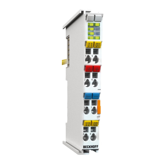
Page 17: Fig. 4 El3751, El3751-0004, El3751-0024; Leds, Connections And Assignment
The nominal measuring range referred to above is part of the total available and usable technical measuring range, which for the EL3751 is approx. ±107%, depending on the measuring range. The "extended range" property can be disabled, in order to make the behavior compatible with the EL30/31/36xx "legacy range". - Page 18 Non-linear characteristic sensor curves can be corrected flexibly through an integrated sampling points table. Simple mathematical operations are also possible. Each terminal has a unique ID number, which is printed and electronically readable. The optionally available factory calibration certificate (EL3751-0020, EL3751-0024) can be assigned via this ID number; re-calibration is possible. Technical data 2.2.1...
- Page 19 Product overview Technical data EL3751 • Voltage between every contact point and SGND (shield, mounting rail): see information to electrical isolation Note: -U , corresponds to internal GND Recommended operation voltage range to max. permitted voltage during specified normal compliance with specification (U...
-
Page 20: Fig. 5 Basic Range Of A Process Data Value
The channel for this terminal features an option to set the measuring range either to the conventional Beckhoff type, up until now: "nominal full-scale value = PDO end value: LegacyRange" or the new method "technical full-scale value = PDO end value: ExtendedRange". - Page 21 ◦ Overrange/Underrange, Error bit and Error LED are set simultaneously if the nominal/technical measuring range is exceeded or not met. ◦ can be optionally activated in the terminal. ◦ this mode is defined by an integer end value; assuming that the LSB step is no longer a whole number. EL3751 Version: 3.9...
- Page 22 Depending on the work involved, the measurement/measured value is subject to a random measuring error that cannot be eliminated. With its practically determined specification data, Beckhoff provides an approach that can be used to calculate the residual measurement uncertainty in the individual case. The following paragraphs elucidate this.
- Page 23 The independent specification data can be divided into two groups: • the data on offset/gain deviation, non-linearity, and repeatability, whose effect on the measurement cannot be influenced by the user. These are summarized by Beckhoff according to the calculation below, at "basic accuracy at 23°C".
- Page 24 Total measurement accuracy = basic accuracy & noise & temperature values according to above formula Beckhoff usually gives the specification data symmetrically in [±%], i.e. ±0.01% or ±100 ppm. Accordingly, therefore, the unsigned total range would be double this given value. A peak-to-peak specification is a total range specification;...
- Page 25 Error coefficient of ageing If the specification value for aging from Beckhoff has not (yet) been specified, it must be assumed to be 0 ppm when considering measurement uncertainty, as in the above example, even if in reality it can be assumed that the measurement uncertainty of the device under consideration changes over the operating time, or colloquially stated, the measured value "drifts".
- Page 26 Input impedance ±Input 1 Differential 570 kΩ || 11 nF typ. CommonMode 140 kΩ || 40 nF typ. (Internal resistance) Methodology: Resistor against -U , capacitance against SGND Input impedance ±Input 2 No usage of this input in this mode Version: 3.9 EL3751...
-
Page 27: Fig. 6 Representation ±30 V Measurement Range
Error = TRUE is also displayed. The detection limit for Underrange/Overrange Error can be set in the CoE. In Legacy Range mode, an Underrange/Overrange event also leads to an Error in the PDO status. Fig. 7: Frequency response ±30 V measurement range, f = 10 kHz, integrated filter 1/2 deactivated sampling EL3751 Version: 3.9... - Page 28 Input impedance ±Input 2 No usage of this input in this mode According to the Beckhoff „measurement error” a reference value can be calculated as specified in section “General information on measuring accuracy/measurement uncertainty” [} 22]. That result is for the measurement range ±10V by the above given data and an environment temperature of = 55°C to ±321 ppm...
-
Page 29: Fig. 8 Representation ±10 V Measurement Range
Error = TRUE is also displayed. The detection limit for Underrange/Overrange Error can be set in the CoE. In Legacy Range mode, an Underrange/Overrange event also leads to an Error in the PDO status. Fig. 9: Frequency response ±10 V measurement range, f = 10 kHz, integrated filter 1/2 deactivated sampling EL3751 Version: 3.9... - Page 30 Input impedance ±Input 1 Differential 4.1 MΩ || 11 nF typ. CommonMode 1 MΩ || 40 nF typ. (Internal resistance) Methodology: Resistor against -U , capacitance against SGND Input impedance ±Input 2 No usage of this input in this mode Version: 3.9 EL3751...
-
Page 31: Fig. 10 Representation ±5 V Measurement Range
Error = TRUE is also displayed. The detection limit for Underrange/Overrange Error can be set in the CoE. In Legacy Range mode, an Underrange/Overrange event also leads to an Error in the PDO status. Fig. 11: Frequency response ±5 V measurement range, f = 10 kHz, integrated filter 1/2 deactivated sampling EL3751 Version: 3.9... - Page 32 Input impedance ±Input 1 Differential 4.1 MΩ || 11 nF typ. CommonMode 1 MΩ || 40 nF typ. (Internal resistance) Methodology: Resistor against -U , capacitance against SGND Input impedance ±Input 2 No usage of this input in this mode Version: 3.9 EL3751...
-
Page 33: Fig. 12 Representation ±2.5 V Measurement Range
Error = TRUE is also displayed. The detection limit for Underrange/Overrange Error can be set in the CoE. In Legacy Range mode, an Underrange/Overrange event also leads to an Error in the PDO status. Fig. 13: Frequency response ±2.5 V measurement range, f = 10 kHz, integrated filter 1/2 deactivated sampling EL3751 Version: 3.9... - Page 34 Input impedance ±Input 1 Differential 4.1 MΩ || 11 nF typ. CommonMode 1 MΩ || 40 nF typ. (Internal resistance) Methodology: Resistor against -U , capacitance against SGND Input impedance ±Input 2 No usage of this input in this mode Version: 3.9 EL3751...
-
Page 35: Fig. 14 Representation ±1.25 V Measurement Range
Error = TRUE is also displayed. The detection limit for Underrange/Overrange Error can be set in the CoE. In Legacy Range mode, an Underrange/Overrange event also leads to an Error in the PDO status. Fig. 15: Frequency response ±1.25 V measurement range, f = 10 kHz, integrated filter 1/2 deactivated sampling EL3751 Version: 3.9... - Page 36 Input impedance ±Input 1 Differential 4.1 MΩ || 11 nF typ. CommonMode 1 MΩ || 40 nF typ. (Internal resistance) Methodology: Resistor against -U , capacitance against SGND Input impedance ±Input 2 No usage of this input in this mode Version: 3.9 EL3751...
-
Page 37: Fig. 16 Representation ±640 Mv Measurement Range
Error = TRUE is also displayed. The detection limit for Underrange/Overrange Error can be set in the CoE. In Legacy Range mode, an Underrange/Overrange event also leads to an Error in the PDO status. Fig. 17: Frequency response ±640 mV measurement range, f = 10 kHz, integrated filter 1/2 deactivated sampling EL3751 Version: 3.9... - Page 38 Input impedance ±Input 1 Differential 4.1 MΩ || 11 nF typ. CommonMode 1 MΩ || 40 nF typ. (Internal resistance) Methodology: Resistor against -U , capacitance against SGND Input impedance ±Input 2 No usage of this input in this mode Version: 3.9 EL3751...
-
Page 39: Fig. 18 Representation ±320 Mv Measurement Range
Error = TRUE is also displayed. The detection limit for Underrange/Overrange Error can be set in the CoE. In Legacy Range mode, an Underrange/Overrange event also leads to an Error in the PDO status. Fig. 19: Frequency response ±320 mV measurement range, f = 10 kHz, integrated filter 1/2 deactivated sampling EL3751 Version: 3.9... - Page 40 Input impedance ±Input 1 Differential 4.1 MΩ || 11 nF typ. CommonMode 1 MΩ || 40 nF typ. (Internal resistance) Methodology: Resistor against -U , capacitance against SGND Input impedance ±Input 2 No usage of this input in this mode Version: 3.9 EL3751...
-
Page 41: Fig. 20 Representation ±160 Mv Measurement Range
Error = TRUE is also displayed. The detection limit for Underrange/Overrange Error can be set in the CoE. In Legacy Range mode, an Underrange/Overrange event also leads to an Error in the PDO status. Fig. 21: Frequency response ±160 mV measurement range, f = 10 kHz, integrated filter 1/2 deactivated sampling EL3751 Version: 3.9... - Page 42 Input impedance ±Input 1 Differential 4.1 MΩ || 11 nF typ. CommonMode 1 MΩ || 40 nF typ. (Internal resistance) Methodology: Resistor against -U , capacitance against SGND Input impedance ±Input 2 No usage of this input in this mode Version: 3.9 EL3751...
-
Page 43: Fig. 22 Representation ±80 Mv Measurement Range
Error = TRUE is also displayed. The detection limit for Underrange/Overrange Error can be set in the CoE. In Legacy Range mode, an Underrange/Overrange event also leads to an Error in the PDO status. Fig. 23: Frequency response ±80 mV measurement range, f = 10 kHz, integrated filter 1/2 deactivated sampling EL3751 Version: 3.9... - Page 44 Input impedance ±Input 1 Differential 4.1 MΩ || 11 nF typ. CommonMode 1 MΩ || 40 nF typ. (Internal resistance) Methodology: Resistor against -U , capacitance against SGND Input impedance ±Input 2 No usage of this input in this mode Version: 3.9 EL3751...
-
Page 45: Fig. 24 Representation ±40 Mv Measurement Range
Error = TRUE is also displayed. The detection limit for Underrange/Overrange Error can be set in the CoE. In Legacy Range mode, an Underrange/Overrange event also leads to an Error in the PDO status. Fig. 25: Frequency response ±40 mV measurement range, f = 10 kHz, integrated filter 1/2 deactivated sampling EL3751 Version: 3.9... - Page 46 Input impedance ±Input 1 Differential 4.1 MΩ || 11 nF typ. CommonMode 1 MΩ || 40 nF typ. (Internal resistance) Methodology: Resistor against -U , capacitance against SGND Input impedance ±Input 2 No usage of this input in this mode Version: 3.9 EL3751...
-
Page 47: Fig. 26 Representation ±20 Mv Measurement Range
Error = TRUE is also displayed. The detection limit for Underrange/Overrange Error can be set in the CoE. In Legacy Range mode, an Underrange/Overrange event also leads to an Error in the PDO status. EL3751 Version: 3.9... - Page 48 Input impedance ±Input 1 Differential 4.1 MΩ || 11 nF typ. CommonMode 1 MΩ || 40 nF typ. (Internal resistance) Methodology: Resistor against -U , capacitance against SGND Input impedance ±Input 2 No usage of this input in this mode Version: 3.9 EL3751...
-
Page 49: Fig. 27 Representation ±10 Mv Measurement Range
Error = TRUE is also displayed. The detection limit for Underrange/Overrange Error can be set in the CoE. In Legacy Range mode, an Underrange/Overrange event also leads to an Error in the PDO status. EL3751 Version: 3.9... - Page 50 Input impedance ±Input 1 Differential 4.1 MΩ || 11 nF typ. CommonMode 1 MΩ || 40 nF typ. (Internal resistance) Methodology: Resistor against -U , capacitance against SGND Input impedance ±Input 2 No usage of this input in this mode Version: 3.9 EL3751...
-
Page 51: Fig. 28 Representation ±5 Mv Measurement Range
Error = TRUE is also displayed. The detection limit for Underrange/Overrange Error can be set in the CoE. In Legacy Range mode, an Underrange/Overrange event also leads to an Error in the PDO status. EL3751 Version: 3.9... - Page 52 Input impedance ±Input 1 Differential 4.1 MΩ || 11 nF typ. CommonMode 1 MΩ || 40 nF typ. (Internal resistance) Methodology: Resistor against -U , capacitance against SGND Input impedance ±Input 2 No usage of this input in this mode Version: 3.9 EL3751...
-
Page 53: Fig. 29 Representation 0
If the "UnderrangeError" detection is to be set even less sensitive, the magnitude of the negative limit value in the CoE object referred to above can be set even higher. Fig. 30: Frequency response 0…5 V measurement range, f = 10 kHz, integrated filter 1/2 deactivated sampling EL3751 Version: 3.9... - Page 54 Input impedance ±Input 1 Differential 4.1 MΩ || 11 nF typ. CommonMode 1 MΩ || 40 nF typ. (Internal resistance) Methodology: Resistor against -U , capacitance against SGND Input impedance ±Input 2 No usage of this input in this mode Version: 3.9 EL3751...
-
Page 55: Fig. 31 Representation 0
If the "UnderrangeError" detection is to be set even less sensitive, the magnitude of the negative limit value in the CoE object referred to above can be set even higher. Fig. 32: Frequency response 0…10 V measurement range, f = 10 kHz, integrated filter 1/2 deactivated sampling EL3751 Version: 3.9... - Page 56 Input impedance ±Input 1 Differential 200 Ω || 11 nF typ. CommonMode 1 MΩ || 40 nF typ. (Internal resistance) Methodology: Resistor against -U , capacitance against SGND Input impedance ±Input 2 No usage of this input in this mode Version: 3.9 EL3751...
-
Page 57: Fig. 33 Representation Current Measurement Range ±20 Ma
Error = TRUE is also displayed. The detection limit for Underrange/Overrange Error can be set in the CoE. In Legacy Range mode, an Underrange/Overrange event also leads to an Error in the PDO status. Fig. 34: Frequency response ±20 mA measurement range, f = 10 kHz, integrated filter 1/2 deactivated sampling EL3751 Version: 3.9... - Page 58 Input impedance ±Input 1 Differential 200 Ω || 11 nF typ. CommonMode 1 MΩ || 40 nF typ. (Internal resistance) Methodology: Resistor against -U , capacitance against SGND Input impedance ±Input 2 No usage of this input in this mode Version: 3.9 EL3751...
-
Page 59: Fig. 35 Representation Current Measurement Range 0
Product overview Current measurement range 0…20 mA Fig. 35: Representation current measurement range 0…20 mA Fig. 36: Frequency response 0…20 mA measurement range, f = 10 kHz, integrated filter 1/2 sampling deactivated EL3751 Version: 3.9... - Page 60 Input impedance ±Input 1 Differential 200 Ω || 11 nF typ. CommonMode 1 MΩ || 40 nF typ. (Internal resistance) Methodology: Resistor against -U , capacitance against SGND Input impedance ±Input 2 No usage of this input in this mode Version: 3.9 EL3751...
-
Page 61: Fig. 37 Representation Current Measurement Range 4
The process data value of 0x00000000 is not undershot. If the "UnderrangeError" detection is to be set even less sensitive, the magnitude of the negative limit value in the CoE object referred to above can be set even higher. EL3751 Version: 3.9... -
Page 62: Fig. 38 Frequency Response 4
Product overview Fig. 38: Frequency response 4…20 mA measurement range, f = 10 kHz, integrated filter 1/2 sampling deactivated Version: 3.9 EL3751... - Page 63 Input impedance ±Input 1 Differential 200 Ω || 11 nF typ. CommonMode 1 MΩ || 40 nF typ. (Internal resistance) Methodology: Resistor against -U , capacitance against SGND Input impedance ±Input 2 No usage of this input in this mode EL3751 Version: 3.9...
-
Page 64: Fig. 39 Chart: Current Measuring Range 3.6
CoE Object 0x8000:2E (Scaler) [} 95] is not declined, the parameter is not changed. Fig. 40: Frequency response 20 mA measurement range, f = 10 kHz, integrated filter 1/2 deactivated sampling Version: 3.9 EL3751... - Page 65 Taking into account the uncertainty associated with this supply line resistance, it can then be included statically in the calculation, in the EL3751 via 0x8000:13 [} 95] and in the ELM350x/ ELM370x via 0x80n0:13 [} 95].
- Page 66 < 86 [digits] Noise, PtP < 3.0 [ppm < 23 [digits] Noise, RMS Max. SNR > 110.5 [dB] Common-mode rejection ratio (without filtering) 50 Hz: 1 kHz: < 150 Ω/V < 0.6 kΩ/V < 3.5 kΩ/V typ. typ. typ. Version: 3.9 EL3751...
- Page 67 < 150 Ω/V < 20 Ω/V < 0.1 Ω/V typ. typ. typ. Largest short-term deviation during a specified electrical ±0.1% = 1000 ppm typ. interference test ) Values related to a common mode interference between SGND and internal ground. EL3751 Version: 3.9...
-
Page 68: Fig. 41 Representation Resistance Measurement Range 5 Kω
Error = TRUE is also displayed. The detection limit for Underrange/Overrange Error can be set in the CoE. In Legacy Range mode, an Underrange/Overrange event also leads to an Error in the PDO status. Version: 3.9 EL3751... -
Page 69: Fig. 42 Chart: Rtd Measuring Range
0.013 K/K 185.2 3904.8 0°C 0°C PT500 -200 approx. ±1.03K @ approx. ±0.34K @ approx. 0.034 K/K 92.6 1952.4 0°C 0°C PT200 -200 approx. ±1.96K @ approx. ±0.65K @ approx. 0.065 K/K 37.04 780.96 0°C 0°C EL3751 Version: 3.9... - Page 70 Higher measuring accuracy for individual sensor types whose resistance is in the smaller subrange of 0..5 kΩ. Relative error according to the slope of the respective RTD characteristic diagram at 23°C ambient terminal temperature (not taking into account temperature drift of the sensor). Version: 3.9 EL3751...
- Page 71 • Until FW07: Object 0x8000:2E (Scaler) [} 95] will be ignored by this setting. The “Legacy Range Mode” applies in the background. • From FW08: Object 0x8000:2E (Scaler) [} 95] will then be set to the “Legacy Range Mode”. A change is not possible as long RTD measurement range is selected. EL3751 Version: 3.9...
- Page 72 Common-mode rejection ratio (without filtering) 50 Hz: 1 kHz: < 3 typ. < 9 typ. < 140 typ. Common-mode rejection ratio (with 50Hz filtering) 50 Hz: 1 kHz: < 3 typ. < 0.2 typ. < 5 typ. Version: 3.9 EL3751...
-
Page 73: Fig. 43 Representation Potentiometer Measurement Range
Error = TRUE is also displayed. The detection limit for Underrange/Overrange Error can be set in the CoE. In Legacy Range mode, an Underrange/Overrange event also leads to an Error in the PDO status. EL3751 Version: 3.9... - Page 74 The integrated supply can be used as power supply. An external supply is permitted, as long as 5 V is not exceeded. The transition resistance values of the terminal contacts affect the measurement. The measuring error can be reduced further through compensation by the user, with active signal connection. Version: 3.9 EL3751...
- Page 75 Product overview Full bridge calculation: The strain relationship (µStrain, µε) is as follows: EL3751 Version: 3.9...
- Page 76 CommonMode 1 MΩ || 40 nF typ. (Internal resistance) Methodology: Resistor against -U , capacitance against SGND Input impedance ±Input 2 No usage of this input in this mode ) Values related to a common mode interference between SGND and internal ground. Version: 3.9 EL3751...
- Page 77 < 1328 [digits] Noise, RMS Max. SNR > 75.4 [dB] Noisedensity@1kHz < 76.93 Noise (with 50 Hz FIR filtering) < 77 [ppm < 602 [digits] Noise, PtP < 15 [ppm < 117 [digits] Noise, RMS Max. SNR > 96.5 [dB] EL3751 Version: 3.9...
-
Page 78: Fig. 44 Representation Measuring Range Sg 1/1 Bridge
Product overview The channel value (PDO) is interpreted directly [mV/V]: Fig. 44: Representation measuring range SG 1/1 bridge Version: 3.9 EL3751... - Page 79 The resistor of the bridge is positioned parallel to the internal resistor of the terminal and leads to an offset shifting respectively. The Beckhoff factory calibration will be carried out with the half bridge 350 Ω, thus the values specified above are directly valid for the 350 Ω half bridge. By connection of another dimensioned half-bridge is to: •...
- Page 80 Other configurations (e.g. R or R variable) of half bridges are not supported The strain relationship (µStrain, µε) is as follows: N should be chosen based on the mechanical configuration of the variable resistors (Poisson, 2 active uniaxial, …). Version: 3.9 EL3751...
- Page 81 < 145 ppm < 1133 [digits] Noise. RMS Max. SNR > 76.8 dB Noisedensity @1kHz < 32.81 Noise (with 50 Hz FIR < 70 ppm < 547 [digits] Noise. PtP filtering) < 15 ppm < 117 [digits] Noise. RMS EL3751 Version: 3.9...
- Page 82 = ±2000 ppm typ. electrical interference test ) Values related to a common mode interference between SGND and internal ground. ) Specifications valid for HW Version ≥ 10, only! Valid specifications until HW Version 10 are as follows: Version: 3.9 EL3751...
- Page 83 < 1875 [digits] Noise. RMS Max. SNR > 72.4 dB Noisedensity @1kHz < 54.31 Noise (with 50 Hz FIR filtering) < 96 ppm < 750 [digits] Noise. PtP < 16 ppm < 125 [digits] Noise. RMS Max. SNR > 95.9 dB EL3751 Version: 3.9...
-
Page 84: Fig. 45 Representation Measuring Range Sg 1/2 Bridge
Product overview The channel value (PDO) is interpreted directly [mV/V]: Fig. 45: Representation measuring range SG 1/2 bridge Version: 3.9 EL3751... - Page 85 Quarter bridge calculation: are the internal switchable input resistors of the terminal. 2/3/4 The strain relationship (µStrain, µε) is as follows: For the quarter bridge, N=1 always applies. EL3751 Version: 3.9...
- Page 86 Max. SNR > 73.1 [dB] Noisedensity @1kHz < 37.36 Noise (with 50 Hz FIR filtering, at < 6 [ppm < 520 [digits] Noise, PtP 23°C) < 1 [ppm < 86 [digits] Noise, RMS Max. SNR > 99.2 [dB] Version: 3.9 EL3751...
- Page 87 Largest short-term deviation during a specified electrical ±1% typ. interference test ) Values related to a common mode interference between SGND and internal ground. The channel value (PDO) can be interpolated in ±12 Ω or ±25 mV/V: EL3751 Version: 3.9...
-
Page 88: Fig. 46 Representation Measuring Range Sg 1/4 Bridge 120 Ω
Product overview Fig. 46: Representation measuring range SG 1/4 bridge 120 Ω Version: 3.9 EL3751... - Page 89 Quarter bridge calculation: are the internal switchable input resistors of the terminal. 2/3/4 The strain relationship (µStrain, µε) is as follows: For the quarter bridge, N=1 always applies. EL3751 Version: 3.9...
- Page 90 1 kHz: < 2 Ω/V < 8 Ω/V < 150 Ω/V typ. typ. typ. Common-mode rejection ratio (with 50 Hz FIR filtering) 50 Hz: 1 kHz: < 700 mΩ/V < 90 mΩ/V < 0.5 mΩ/V typ. typ. typ. Version: 3.9 EL3751...
- Page 91 Largest short-term deviation during a specified electrical ±1% typ. interference test ) Values related to a common mode interference between SGND and internal ground. The channel value (PDO) can be interpolated in ±12 Ω or ±8.571 mV/V: EL3751 Version: 3.9...
-
Page 92: Fig. 47 Representation Measuring Range Sg 1/4 Bridge 350 Ω
Product overview Fig. 47: Representation measuring range SG 1/4 bridge 350 Ω Version: 3.9 EL3751... - Page 93 Commissioning Commissioning Notes to short documentation NOTICE This short documentation does not contain any further information within this chapter. For the complete documentation please contact the Beckhoff sales department responsible for you. EL3751 Version: 3.9...
- Page 94 Default (hex) 7000:0 PAI Control UINT8 0x02 (2 Ch.1 7000:01 Integrator Reset Restart of the integration with rising BOOLEAN 0x00 (0 edge 7000:02 Peak Hold Start new peak value detection with BOOLEAN 0x00 (0 Reset rising edge Version: 3.9 EL3751...
- Page 95 4 - PT500 (-200...850°C) 5 - PT200 (-200...850°C) 6 - NI1000 (-60...250°C) 7 - NI1000 TK5000 or rather 100°C: 1500Ohm (-30...160°C) 8 - NI120 (-60...320°C) 9 - KT100/110/130/210/230 KTY10/11/13/16/19 (-50...150°C) 10 - KTY81/82-110,120,150 (-50...150°C) 11 - KTY81-121 (-50...150°C) EL3751 Version: 3.9...
- Page 96 2 - Integrator 2x 3 - Differentiator 1x 4 - Differentiator 2x 8000:2D Differentiator Distance of samples for the differentiation UINT16 0x0001 (1 Samples Delta 8000:2E Scaler Scaling (enum): UINT16 0x0000 (0 0 - Extended Range 1 - Linear Version: 3.9 EL3751...
- Page 97 LookUp table with 50 x/y value pairs 8005:01 Scaler Offset/ Scaling offset INT32 0x00000000 (0 Scaler Value 1 or LookUp x-value 1 8005:02 Scaler-Gain/ Scaling gain INT32 0x00000000 (0 Scaler Value 2 or LookUp y-value 1 8005:03 Scaler Value 3 LookUp x-value 2 INT32 0x00000000 (0 EL3751 Version: 3.9...
- Page 98 (T3S1 * temp * sample) 3.2.10 0x800F PAI Vendor Calibration Data Ch.1 Index Name Meaning Data type Flags Default (hex) 800F:0 PAI Vendor UINT8 0x0C (12 Calibration Data Ch.1 800F:01 Calibration Date Date of calibration OCTET- STRING[4] Version: 3.9 EL3751...
- Page 99 Current absolute minimum value INT32 0x00000000 Peak Hold 9000:07 Actual Positive Current absolute maximum value INT32 0x00000000 Peak Hold 9000:08 Previous Absolute minimum value up to last INT32 0x00000000 Negative Peak rising edge of "Peak Hold Reset" Hold EL3751 Version: 3.9...
- Page 100 9000:14 Vendor Writing counter for vendor calibration UINT16 0x0000 (0 Calibration data Counter 9000:15 User Calibration Writing counter for user calibration data UINT16 0x0000 (0 Counter ) available from revision -0019 ) available from revision -0020 Version: 3.9 EL3751...
- Page 101 900F:33 Vendor SG 1/4 OCTET- 3Wire 350R STRING[4] 900F:34 Vendor SG 1/4 OCTET- 3Wire 120R STRING[4] 900F:35 Vendor SG 1/2 OCTET- 3Wire STRING[4] 900F:36 Vendor SG 1/2 OCTET- 5Wire STRING[4] 900F:37 Vendor SG 1/1 OCTET- 4Wire STRING[4] EL3751 Version: 3.9...
- Page 102 900F:B2 User SG 1/4 OCTET- 2Wire 120R STRING[4] 900F:B3 User SG 1/4 OCTET- 3Wire 350R STRING[4] 900F:B4 User SG 1/4 OCTET- 3Wire 120R STRING[4] 900F:B5 User SG 1/2 OCTET- 3Wire STRING[4] 900F:B6 User SG 1/2 OCTET- 5Wire STRING[4] Version: 3.9 EL3751...
- Page 103 0x01 (1 F010:01 Subindex 001 UINT32 0x0000015E (350 3.2.17 0xF600 PAI Timestamp Index Name Meaning Data type Flags Default (hex) F600:0 PAI Timestamp UINT8 0x02 (2 F600:01 Low Timestamp (low) UINT32 0x00000000 F600:02 Hi Timestamp (hi) UINT32 0x00000000 EL3751 Version: 3.9...
- Page 104 FB00:02 Status Command status UINT8 0x00 (0 This indicates that the command is still running or has been executed. Functional dependent, see respective sections. Otherwise: 0: Command not existing 1: executed without errors 2,3: executed not successful Version: 3.9 EL3751...
-
Page 105: Fig. 48 Opening The *. Tnzip Archive
EtherCAT system documentation. • The EtherCAT device of the example should usually be declared your present system. After selection of the EtherCAT device in the “Solutionexplorer” select the “Adapter” tab and click on “Search...”: EL3751 Version: 3.9... -
Page 106: Fig. 49 Search Of The Existing Hw Configuration For The Ethercat Configuration Of The Example
-archive file into a temporary working folder. • Create a new TwinCAT project as described in section: TwinCAT Quickstart, TwinCAT 3, Startup [} 154] • Open the context menu of "PLC" within the "Solutionexplorer" and select "Add Existing Item..." Version: 3.9 EL3751... - Page 107 3.3.1 Sample program 1 and 2 (offset/gain) Download TwinCAT 3 project: https://infosys.beckhoff.com/content/1033/el3751/Resources/2152667403/.zip Program description / function: • Calculation of an Offset (correction) value on the basis of the amplitudes of an AC input voltage (DC component ≠ 0) until a deviation of the offset smaller than "wOFFSET_MIN_VAL_REF" (in digits) is achieved.
- Page 108 // For CoE Object 0x8005 access: fb_coe_write :FB_EcCoESdoWrite; // FB for writing to CoE nSTATE_WRITE_COE :BYTE := 0; nSubIndex :BYTE; nCoEIndexScaler :WORD := 16#8005; // Use channel 1 // For ELM3xxx this is 0x8006 nSubIndScalGain :BYTE := 16#02; nSubIndScalOffs :BYTE := 16#01; nADSErrId :UDINT; // Copy of ADS-Error ID // =============================================== fb_get_min_max :FB_GET_MIN_MAX; // Min/Max values needed // Note: you may also use "FB_ALY_MinMaxAvg_1Ch" of TwinCAT analytics) // instead; there avg (average values can also be determinated // Variables used for offset scaling: nSTATE_SCALE_OFFSET :INT := 0; bScaleOffsetStart :BOOL := FALSE; bScaleOffsetDone :BOOL := FALSE; fOffsetDeviationVal :REAL; nOFFSET_MIN_VAL_REF :WORD := 200; // Max. limit value for offset // Variables used for gain scaling: nSTATE_SCALE_GAIN :INT := 0; bScaleGainStart :BOOL := FALSE; bScaleGainDone :BOOL := FALSE; nPRESET_MAX_VAL :REAL := 3000000; // Target amplitude value // =============================================== // Variables for evaluating of gain and offset: nOffset :REAL := 0; // Offset value nGain :REAL := 1; // Gain value nScaledSampleVal :REAL; nDINT_Value :DINT; fb_trig_bEnable :R_TRIG; // Trigger FB for Enable bError :BOOL := FALSE; // Evaluate.. END_VAR Execution part: // THIS CODE IS ONLY AN EXAMPLE - YOU HAVE TO CHECK APTITUDE FOR YOUR APPLICATION Version: 3.9 EL3751...
- Page 109 nOffset:= 0; nGain := 1; bScaleOffsetStart := bScalingOrder; bScaleGainStart := NOT bScalingOrder; fb_get_min_max.nMinFreqInput := fMinFrequencyIn; nMainCal_State := 10; // Start END_IF 10: IF (bScaleGainDone AND NOT bScalingOrder) OR (bScaleOffsetDone AND bScalingOrder) THEN bScaleOffsetStart := NOT bScalingOrder; bScaleGainStart := bScalingOrder; nMainCal_State := nMainCal_State + 10; END_IF 20: IF bScaleGainDone AND bScaleOffsetDone THEN nMainCal_State :=0; // All done, initalization for next start END_IF END_CASE // ----- Offset scaling (program 1) ----- IF bScaleOffsetStart THEN CASE nSTATE_SCALE_OFFSET OF 0: bScaleOffsetDone := FALSE; // Initialization of confirmation flag // Get min/max values within a period of the signal: fb_get_min_max(nInputValue:=nScaledSampleVal); IF fb_get_min_max.bRESULT THEN // Wait if Limit-Values are valid // Min/Max Values valid, continue.. // calculate current offset deviation: fOffsetDeviationVal := (fb_get_min_max.nMaxVal - ABS((fb_get_min_max.nMaxVal-fb_get_min_max.nMinVal)/2)); // Offset deviation check: IF ABS(fOffsetDeviationVal) < nOFFSET_MIN_VAL_REF THEN // Deviation in acceptable range - offset scaling done, // now write correction value into CoE Object: nDINT_Value := REAL_TO_DINT(nOffset); // Initiate writing to CoE: EL3751 Version: 3.9...
- Page 110 nSTATE_SCALE_OFFSET := 0; END_IF END_CASE END_IF // ----- Gain scaling (program 2) ----- IF bScaleGainStart THEN CASE nSTATE_SCALE_GAIN OF 0: bScaleGainDone := FALSE; // Initialization of confirmation flag // Get min/max values within a period of the signal: fb_get_min_max(nInputValue:=DINT_TO_REAL(nPAI_Sample)); IF fb_get_min_max.bRESULT THEN // Wait if Limit-Values are valid // Calculate Gain nGain := nPRESET_MAX_VAL/ABS((fb_get_min_max.nMaxVal-fb_get_min_max.nMinVal)/2); // ..shift gain value by 16 Bit left and convert to DINT: nDINT_Value := REAL_TO_DINT(65536 * nGain); //Due to 'output = gain * input + offset', the offset have to be adapted: nOffset := nOffset * nGain; // Initiate writing to CoE: nSubIndex := nSubIndScalGain; nSTATE_WRITE_COE := 10; nSTATE_SCALE_GAIN := nSTATE_SCALE_GAIN + 10; END_IF 10: IF(nSTATE_WRITE_COE = 0) THEN IF NOT (nOffset = 0) THEN // (bScalingOrder is TRUE) nDINT_Value := REAL_TO_DINT(nOffset); // Initiate writing to CoE (again): nSubIndex := nSubIndScalOffs; nSTATE_WRITE_COE := 10; END_IF nSTATE_SCALE_GAIN := nSTATE_SCALE_GAIN + 10; END_IF 20: IF(nSTATE_WRITE_COE = 0) THEN // Scaling gain done within CoE of the device Version: 3.9 EL3751...
- Page 111 ); nSTATE_WRITE_COE := nSTATE_WRITE_COE + 10; 20: // Write nDINT_Value to CoE Index "Scaler": fb_coe_write( nSubIndex:= nSubIndex, pSrcBuf:= ADR(nDINT_Value), cbBufLen:= SIZEOF(nDINT_Value), bExecute:= TRUE ); nSTATE_WRITE_COE := nSTATE_WRITE_COE + 10; 30: fb_coe_write(); IF NOT fb_coe_write.bBusy THEN nSTATE_WRITE_COE := 0; END_IF END_CASE ELSE nSTATE_WRITE_COE := 0; END_IF END_IF IF(fb_coe_write.bError) AND NOT bError THEN bError := TRUE; nADSErrId := fb_coe_write.nErrId; // CoE write acccess error occured: reset all nSTATE_WRITE_COE := nMainCal_State := 0; bScaleOffsetDone := bScaleOffsetStart := FALSE; bScaleGainDone := bScaleGainStart := FALSE; END_IF 3.3.1.1 Function block FB_GET_MIN_MAX Declaration part: FUNCTION_BLOCK FB_GET_MIN_MAX VAR CONSTANT EL3751 Version: 3.9...
- Page 112 bValidMaxVal :BOOL; fbGetCurTaskIdx : GETCURTASKINDEX; END_VAR Execution part: IF bInit THEN // Counter initialization: // [counter value] > [1/(<input frequency> * TaskCycleTime)] fbGetCurTaskIdx(); CMMcnt := REAL_TO_UINT( 1.1E7/(nMinFreqInput*UDINT_TO_REAL( _TaskInfo[fbGetCurTaskIdx.index].CycleTime))); // At least an entire period have to be sampled for min/max determination // Initialization, go on: nMaxValCnt :=CMMcnt; nMinValCnt :=CMMcnt; nMaxVal :=CMAXinit; nMinVal :=CMINinit; bInit := FALSE; END_IF // Assertions: new min/max values exists: bValidMaxVal := TRUE; bValidMinVal := TRUE; // Filter min/max values IF (nMaxVal < nInputValue) THEN bValidMaxVal := FALSE; nMaxVal := nInputValue; // Max value was found END_IF IF (nMinVal > nInputValue) THEN bValidMinVal := FALSE; nMinVal := nInputValue; // Min value was found END_IF // Count down, if no new value come in: IF (bValidMaxVal AND (nMaxValCnt > 0)) THEN nMaxValCnt := nMaxValCnt - 1; END_IF // Count down, if no new value come in: Version: 3.9 EL3751...
- Page 113 bRESULT := NOT (nMaxVal = nMinVal); // Sign valid results ELSE bRESULT := FALSE; // Sign still invalid results END_IF 3.3.2 Sample program 3 (write LookUp table) Download TwinCAT 3 project: https://infosys.beckhoff.com/content/1033/el3751/Resources/2152669707/.zip Program description Transmission of LookUp table interpolation values for mapping of an equation f(x) = x via CoE into the terminal. Variable declaration sample program 3 PROGRAM MAIN...
- Page 114 A simple variable query, e.g., via button linked with bEnable, can be used to initiate the transfer. The variable declaration must contain VAR_INPUT bEnable AT%I* :BOOL; END_VAR and the following program lines: IF bEnable AND NOT startWrite THEN bWriteLUT2CoE := TRUE; END_IF 3.3.3 Sample program 4 (generate LookUp table) Download TwinCAT 3 project: https://infosys.beckhoff.com/content/1033/el3751/Resources/2152669707/.zip Version: 3.9 EL3751...
- Page 115 nYvalue : DINT; tRepeatTimerValue : TIME := T#51MS; aLUT : ARRAY[0..99] OF DINT; END_VAR Execution part: // Example program 4: // ################# Recording of 50 sample points: ################# // a) Determination of min./max. values (corresponding to the value range of the sensor) tp_timer(IN:=bGetMinMax, PT:=T#2.51S); // Periodic duration of ramp (+reserve) IF tp_timer.Q THEN nMinValue := MIN(nPAISampleIn, nMinValue); nMaxValue := MAX(nPAISampleIn, nMaxValue); END_IF // b) Recording of values: Start r_trigStartRecord(CLK:=bStartRecord); IF r_trigStartRecord.Q THEN nX := 0; memset(ADR(aLUT), 0 , 100); bRecordLUT := TRUE; END_IF ton_timer(); IF bRecordLUT OR ton_timer.Q THEN bRecordLUT := FALSE; EL3751 Version: 3.9...
- Page 116 • The function block "FB_EcCoESdoWrite" requires the "Tc2_EtherCAT" library • <AmsNetID> must show the local device EtherCAT NetID in inverted commas (e.g. '168.57.1.1.5.1') • <DeviceEtherCATAddress> must show the local device EtherCAT address of the EL3751/ ELM3xxx terminal (e.g., 1007) Variable declaration sample program 5 PROGRAM MAIN...
- Page 117 -0.055674804078696793, 0.07874009379691002, -0.055674804078696793, 0.0009941073749156226, 0.05330627422911416, -0.07775650809213645, 0.05676876756757213, 0.0009722394088121363, -0.0560894442193289, 0.06743018479714939, -0.03677629552114248, 0.00027114381194760643, 0.026329003448584205, -0.0525134329294473, 0.05628409460964408, -0.00005849791174519834, -0.0729038234874446, 0.0664029021294729, -0.007880289104928245, 0.04299467480848277, 0.03663651655662163, 0 ]; nValue :DINT; // Temporary variable END_VAR Execution part: // Example program 5: // writes filter coefficients of // "User defined FIR Filter" (32) // incl. example coefficients for band pass // Note: writing possible, if CoE Object // PAI Settings Ch.1 (0x8000:16) has value 32 or 33 set, only! // (32 = User defined FIR Filter / 33 = User defined IIR Filter) // =============================================================== CASE wState OF EL3751 Version: 3.9...
- Page 118 20 ksps sampling of the signal. The second way is described in this sample: Use of two EL3751 EtherCAT Terminals, each with a maximum sampling rate of 10 kSps (and thus a conversion time of 100 µs in this case, cf. Continuative documentation for I/O components with analog in and outputs [} 262], chapter “Temporal aspects of analog/digital or...
-
Page 119: Fig. 50 Process Of Interlacing The Input Data
"interlaced", the result is a net measured data stream of 20 ksps. Fig. 50: Process of interlacing the input data The following configuration is used for this purpose: Fig. 51: Configuration and setup for sample program 6: Doubling of the sample rate with 2 x EL3751 EL3751 Version: 3.9... -
Page 120: Fig. 52 Setting The Dc Shift Time For Terminal 2
It is therefore not possible to read signals that are twice as fast with twice the sampling rate. Sample: the EL3751 with a sampling rate of 10 ksps can meaningfully (alias-free) read signals up to half the sampling rate = 5 kHz. -
Page 121: Fig. 53 Oversampling 20 Ksps With 2 X El3751 With Input Signals (Below) And Result Signal (Top)
For an input signal with sine 5 kHz and 2.5 V amplitude, for example, the TwinCAT ScopeView provides the following results: Fig. 53: Oversampling 20 ksps with 2 x EL3751 with input signals (below) and result signal (top) The upper diagram shows the total signal and the two input signals (nSample_1, nSample_2), with a time shift of 50 µs relative to each other, within 18 s in compressed form. -
Page 122: Fig. 54 Oversampling 20 Ksps With 2 X El3751 Shows Input Value 1 And Input Value 2 Alternately For A Result Value
Commissioning Fig. 54: Oversampling 20 ksps with 2 x EL3751 shows input value 1 and input value 2 alternately for a result value Under certain conditions, both inputs can be combined into a single variable in a correspondingly fast task. For this purpose the sample program contains an additional task with 50 µs cycle time, which is required for... - Page 123 • In the PLC/ C++, on the time axis, convert to the desired sampling rate, e.g., by linear interpolation based on the timestamp for each input value (sample). Since the EL3751/ ELM3xxx units provide time- equidistant samples based on distributed clocks, this is easily possible.
- Page 124 (the slope) is not constant. For example, input values of a sine signal in the non-linear sections are distorted by the interpolation performed in the program: Version: 3.9 EL3751...
-
Page 125: Fig. 55 Decimation From 20 Μs (Left) To 22.675
The decimation factor is given by entering the value "50/44.1" for nDecimationValue in the sample. If this sample is used for the EL3751 with 500 µs cycle time and 5x oversampling, the sampling interval of 100 µs, which originates from the EL3751, is converted to approx. 113.378.. µs. This sample is designed accordingly. - Page 126 The variable nOVS must contain the same oversampling factor as set in the process data configuration. Download sample program 7: • Configuration: IPC + EK1100 + EL3751 + EL9011: https://infosys.beckhoff.com/content/1033/el3751/Resources/5090848011/.zip • Configuration: IPC + EK1100 + ELM3602‑0002 + EL9011: https://infosys.beckhoff.com/content/1033/el3751/Resources/5117137291/.zip...
- Page 127 // Simulate values: aOVS_SampleSets[i+nOVS] := LREAL_TO_DINT(1000000 * SIN(nPhi)); nPhi := nPhi + 0.01;//0.003141592653; ELSE // Fill current new samples set on right: aOVS_SampleSets[i+nOVS] := aSamples_1[i]; END_IF END_FOR IF bEnable THEN nResultNoOfSamples := 0; // Use for further processing FOR i := 0 TO nOVS-1 DO nDivVar := TRUNC_INT(tDecVar_InTaskCycle/nOVSTimeInterval_ns); // Check, if new value is in grid IF (nDivVar = i) THEN nResultNoOfSamples := nResultNoOfSamples + 1; // Calc slope by the left and right element values (dy/dx): nDY := aOVS_SampleSets[i+1] - aOVS_SampleSets[i]; sVal := DINT_TO_LREAL(nDY)/nOVSTimeInterval_ns; // Get the time (difference) from the left side element start to the desired time point: nDX := tDecVar_InTaskCycle - TRUNC_INT(tDecVar_InTaskCycle/nOVSTimeInterval_ns) * UDINT_TO_LREAL(nOVSTimeInterval_ns); // Calc timestamp tVarDecResult := nDX + ULINT_TO_LREAL(nOVS_CycleCount); // Calc new value: nVarDecResult := LREAL_TO_DINT(DINT_TO_LREAL(aOVS_SampleSets[i]) + sVal * nDX); // next decimation time step tDecVar_InTaskCycle := tDecVar_InTaskCycle + nDecTimeInterval_ns; tDecVar_InTaskCycle := tDecVar_InTaskCycle - INT_TO_UDINT(TRUNC_INT(tDecVar_InTaskCycle/nTaskCycle_ns)) * nTaskCycle_ns; END_IF // Fill timestamp and new value allocated to the field element of its timestamp EL3751 Version: 3.9...
-
Page 128: Fig. 56 Function Block As An Example For Analysis Of Diagnostics Information Of The Terminal
Fig. 56: Function block as an example for analysis of diagnostics information of the terminal Simplified linking via structure variable This example program takes the opportunity to describe a TwinCAT function that simplifies the linking of complex PDO structures. Version: 3.9 EL3751... -
Page 129: Fig. 57 Creation Of Pdo Variables (Twincat Version >= V3.1.4024.0)
This and all configurations are already included in the respective example program: • Example program (variant A – using the “Plc” tab of the terminal): https://infosys.beckhoff.com/content/1033/el3751/Resources/7161530379/.zip • Example program (variant B – using of “Create SM/PDO Variables” by the advanced settings of the terminal): https://infosys.beckhoff.com/content/1033/el3751/Resources/7161533067/.zip... -
Page 130: Fig. 58 Creation Of The Smpdovariables (Twincat Version >= V3.1.4022.30)
The read access to the inputs of the application is provided via the structure st_SM3 and write access to the outputs via the structure st_SM2. These data structures corresponds to the automatically added new PDO element "SmPdoVariables". Version: 3.9 EL3751... -
Page 131: Fig. 60 Visualization Of The Sample Implementation: Calibration Signature
The interface of the function block is structured as follows: VAR_INPUT bInitialize : BOOL := FALSE; // TRUE = Initialised bEnable : BOOL := FALSE; // Activate module tAmsNetIdArr : AMSADDR; // Ads address of the terminal/ box nIfSlectCoE : WORD; // Interface number of the CoE nChSelectCoE : WORD := 1; // Channel number eOption : E_CALSIG_OPTIONS; // Access get/set (read/write) stCoEPAIInfoDataCalCnt : ST_CoE; // Cal. counter object (EL3751/ ELM3xxx) END_VAR VAR_OUTPUT bDone : BOOL; // Process end bCmpResult : BOOL; // Signature comparision: TRUE = equal nInterfaceUserCalCnt : WORD; // Value of calibration counter EL3751 Version: 3.9... - Page 132 In addition, the CoE object for reading the calibration counter must be transferred via 'stCoEPAIInfoDataCalCnt', since this is different for the EL3751/ ELM3xxx terminals. A call is made with "bEnable := TRUE" for activation and with specification of the interface number (nIfSlectCoE) that applies to the terminal to be addressed, the channel (nChSelectCoE) and for reading the stored signature "eOption := E_CALSIG_OPTIONS.get"...
- Page 133 EL3751 Features EL3751 Features NOTICE This short documentation does not contain any further information within this chapter. For the complete documentation please contact the Beckhoff sales department responsible for you. EL3751 Version: 3.9...
-
Page 134: Fig. 61 Selection Of The Diagnostic Information Of An Ethercat Slave
The colors in Fig. Selection of the diagnostic information of an EtherCAT Slave also correspond to the variable colors in the System Manager, see Fig. Basic EtherCAT Slave Diagnosis in the PLC. Colour Meaning yellow Input variables from the Slave to the EtherCAT Master, updated in every cycle Version: 3.9 EL3751... -
Page 135: Fig. 62 Basic Ethercat Slave Diagnosis In The Plc
Fig. Basic EtherCAT Slave Diagnosis in the PLC shows an example of an implementation of basic EtherCAT Slave Diagnosis. A Beckhoff EL3102 (2-channel analogue input terminal) is used here, as it offers both the communication diagnosis typical of a slave and the functional diagnosis that is specific to a channel. - Page 136 The CoE parameter directory (CanOpen-over-EtherCAT) is used to manage the set values for the slave concerned. Changes may, in some circumstances, have to be made here when commissioning a relatively complex EtherCAT Slave. It can be accessed through the TwinCAT System Manager, see Fig. EL3102, CoE directory: Version: 3.9 EL3751...
-
Page 137: Fig. 63 El3102, Coe Directory
Commissioning interfaces are being introduced as part of an ongoing process for EL/EP EtherCAT devices. These are available in TwinCAT System Managers from TwinCAT 2.11R2 and above. They are integrated into the System Manager through appropriately extended ESI configuration files. EL3751 Version: 3.9... -
Page 138: Fig. 64 Example Of Commissioning Aid For A El3204
The target state wanted by the user, and which is brought about automatically at start-up by TwinCAT, can be set in the System Manager. As soon as TwinCAT reaches the status RUN, the TwinCAT EtherCAT Master will approach the target states. Version: 3.9 EL3751... -
Page 139: Fig. 65 Default Behaviour Of The System Manager
In addition, the target state of any particular Slave can be set in the “Advanced Settings” dialogue; the standard setting is again OP. Fig. 66: Default target state in the Slave Manual Control There are particular reasons why it may be appropriate to control the states from the application/task/PLC. For instance: • for diagnostic reasons EL3751 Version: 3.9... -
Page 140: Fig. 67 Plc Function Blocks
The pre-calculated theoretical maximum E-Bus current is displayed in the TwinCAT System Manager as a column value. A shortfall is marked by a negative total amount and an exclamation mark; a power feed terminal is to be placed before such a position. Version: 3.9 EL3751... -
Page 141: Fig. 68 Illegally Exceeding The E-Bus Current
Fig. 69: Warning message for exceeding E-Bus current NOTICE Caution! Malfunction possible! The same ground potential must be used for the E-Bus supply of all EtherCAT terminals in a terminal block! EL3751 Version: 3.9... -
Page 142: Fig. 70 Relationship Between User Side (Commissioning) And Installation
• “offline”: The configuration can be customized by adding and positioning individual components. These can be selected from a directory and configured. ◦ The procedure for the offline mode can be found under http://infosys.beckhoff.com: TwinCAT 2 → TwinCAT System Manager → IO Configuration → Add an I/O device •... -
Page 143: Fig. 71 Control Configuration With Embedded Pc, Input (El1004) And Output (El2008)
Note that all combinations of a configuration are possible; for example, the EL1004 terminal could also be connected after the coupler, or the EL2008 terminal could additionally be connected to the CX2040 on the right, in which case the EK1100 coupler wouldn’t be necessary. EL3751 Version: 3.9... -
Page 144: Fig. 72 Initial Twincat 2 User Interface
In the menu under “Actions” → “Choose Target System...”, the following window is opened for this via the symbol “ ” or the “F8” key: Version: 3.9 EL3751... -
Page 145: Fig. 73 Selection Of The Target System
Once the target system has been entered, it is available for selection as follows (a correct password may have to be entered before this): After confirmation with “OK”, the target system can be accessed via the System Manager. EL3751 Version: 3.9... -
Page 146: Fig. 75 Select "Scan Devices
Confirm the message “Find new boxes”, in order to determine the terminals connected to the devices. “Free Run” enables manipulation of input and output values in “Config Mode” and should also be acknowledged. Based on the example configuration [} 143] described at the beginning of this section, the result is as follows: Version: 3.9 EL3751... -
Page 147: Fig. 77 Mapping Of The Configuration In The Twincat 2 System Manager
TwinCAT PLC Control is the development environment for generating the controller in different program environments: TwinCAT PLC Control supports all languages described in IEC 61131-3. There are two text- based languages and three graphical languages. • Text-based languages ◦ Instruction List (IL) ◦ Structured Text (ST) EL3751 Version: 3.9... - Page 148 The following section refers solely to Structured Text (ST). After starting TwinCAT PLC Control, the following user interface is shown for an initial project: Fig. 79: TwinCAT PLC Control after startup Example variables and an example program have been created and stored under the name “PLC_example.pro”: Version: 3.9 EL3751...
- Page 149 Manager has been notified, the warning no longer appears. First, integrate the TwinCAT PLC Control project in the System Manager. This is performed via the context menu of the PLC configuration (right-click) and selecting “Append PLC Project…”: Fig. 81: Appending the TwinCAT PLC Control project EL3751 Version: 3.9...
- Page 150 “PLC_example” and via “Modify Link...” “Standard”: Fig. 83: Creating the links between PLC variables and process objects In the window that opens, the process object for the “bEL1004_Ch4” BOOL-type variable can be selected from the PLC configuration tree: Version: 3.9 EL3751...
- Page 151 The links can also be checked by selecting “Goto Link Variable” from the context menu of a variable. The opposite linked object, in this case the PDO, is automatically selected: EL3751 Version: 3.9...
- Page 152 The PLC system can then be started as described below. Starting the controller Starting from a remote system, the PLC control has to be linked with the embedded PC over the Ethernet via “Online” → “Choose Runtime System…”: Version: 3.9 EL3751...
- Page 153 This results in the message “No program on the controller! Should the new program be loaded?”, which should be confirmed with “Yes”. The runtime environment is ready for the program start: EL3751 Version: 3.9...
- Page 154 (see “TwinCAT System Manager” of TwinCAT 2) for communication with the electromechanical components. After successful installation of the TwinCAT system on the PC to be used for development, TwinCAT 3 (shell) displays the following user interface after startup: Version: 3.9 EL3751...
- Page 155 First create a new project via (or under “File”→“New”→ “Project…”). In the following dialog, make the corresponding entries as required (as shown in the diagram): Fig. 90: Create new TwinCAT 3 project The new project is then available in the project folder explorer: EL3751 Version: 3.9...
- Page 156 Via the symbol in the menu bar: expand the pull-down menu: and open the following window: Fig. 92: Selection dialog: Choose the target system Version: 3.9 EL3751...
- Page 157 The TwinCAT System Manager may first have to be set to “Config mode” via or via the menu “TwinCAT” → “Restart TwinCAT (Config Mode)”. Fig. 94: Select “Scan” Confirm the warning message, which follows, and select the “EtherCAT” devices in the dialog: EL3751 Version: 3.9...
- Page 158 A scan (search function) can also be initiated by selecting “Device ...” from the context menu, which then only reads the elements below which are present in the configuration: Version: 3.9 EL3751...
- Page 159 The following section refers solely to Structured Text (ST). In order to create a programming environment, a PLC subproject is added to the example project via the context menu of the “PLC” in the project folder explorer by selecting “Add New Item….”: EL3751 Version: 3.9...
- Page 160 Fig. 99: Specifying the name and directory for the PLC programming environment The “Main” program, which already exists due to selecting “Standard PLC project”, can be opened by double-clicking on “PLC_example_project” in “POUs”. The following user interface is shown for an initial project: Version: 3.9 EL3751...
- Page 161 Commissioning on EtherCAT Master Fig. 100: Initial “Main” program for the standard PLC project Now example variables and an example program have been created for the next stage of the process: EL3751 Version: 3.9...
- Page 162 “Assignments” in the project folder explorer: Assigning variables Via the menu of an instance – variables in the “PLC” context, use the “Modify Link…” option to open a window to select a suitable process object (PDO) for linking: Version: 3.9 EL3751...
- Page 163 4 of the EL1004 terminal is selected for linking. In contrast, the checkbox “All types” must be ticked to create the link for the output variables, in order to allocate a set of eight separate output bits to a byte variable in this case. The following diagram shows the whole process: EL3751 Version: 3.9...
- Page 164 PDOs to a variable. However, in this example, it would not be possible to select all output bits for the EL2008, since the terminal only makes individual digital outputs available. If a terminal has a byte, word, Version: 3.9 EL3751...
- Page 165 5. Then the project folder must be created. This can be done either via the key combination “CTRL + Shift + B” or via the “Build” tab in TwinCAT. 6. The structure in the “PLC” tab of the terminal must then be linked to the created instance. EL3751 Version: 3.9...
- Page 166 A few seconds later, the corresponding status of the Run mode is displayed in the form of a rotating symbol at the bottom right of the VS shell development environment. The PLC system can then be started as described below. Version: 3.9 EL3751...
- Page 167 ◦ Connects I/O devices to tasks in a variable-oriented manner ◦ Connects tasks to tasks in a variable-oriented manner ◦ Supports units at the bit level ◦ Supports synchronous or asynchronous relationships ◦ Exchange of consistent data areas and process images EL3751 Version: 3.9...
- Page 168 5.3.1 Installation of the TwinCAT real-time driver In order to assign real-time capability to a standard Ethernet port of an IPC controller, the Beckhoff real-time driver has to be installed on this port under Windows. This can be done in several ways.
- Page 169 Commissioning on EtherCAT Master Fig. 113: Call up under VS Shell (TwinCAT 3) B: Via TcRteInstall.exe in the TwinCAT directory Fig. 114: TcRteInstall in the TwinCAT directory In both cases, the following dialog appears: EL3751 Version: 3.9...
- Page 170 TwinCAT 3: the properties of the EtherCAT device can be opened by double click on “Device .. (EtherCAT)” within the Solution Explorer under “I/O”: After the installation the driver appears activated in the Windows overview for the network interface (Windows Start → System Properties → Network) Version: 3.9 EL3751...
- Page 171 Commissioning on EtherCAT Master Fig. 117: Windows properties of the network interface A correct setting of the driver could be: Fig. 118: Exemplary correct driver setting for the Ethernet port Other possible settings have to be avoided: EL3751 Version: 3.9...
- Page 172 Commissioning on EtherCAT Master Fig. 119: Incorrect driver settings for the Ethernet port Version: 3.9 EL3751...
- Page 173 DHCP. In this way the delay associated with the DHCP client for the Ethernet port assigning itself a default IP address in the absence of a DHCP server is avoided. A suitable address space is 192.168.x.x, for example. Fig. 120: TCP/IP setting for the Ethernet port EL3751 Version: 3.9...
- Page 174 The files are read (once) when a new System Manager window is opened, if they have changed since the last time the System Manager window was opened. A TwinCAT installation includes the set of Beckhoff ESI files that was current at the time when the TwinCAT build was created.
- Page 175 1018 in the configuration. This is also stated by the Beckhoff compatibility rule. Refer in particular to the chapter “General notes on the use of Beckhoff EtherCAT IO components” and for manual configuration to the chapter “Offline configuration creation [} 179]”.
- Page 176 Faulty ESI file If an ESI file is faulty and the System Manager is unable to read it, the System Manager brings up an information window. Fig. 126: Information window for faulty ESI file (left: TwinCAT 2; right: TwinCAT 3) Version: 3.9 EL3751...
- Page 177 Commissioning on EtherCAT Master Reasons may include: • Structure of the *.xml does not correspond to the associated *.xsd file → check your schematics • Contents cannot be translated into a device description → contact the file manufacturer EL3751 Version: 3.9...
- Page 178 Commissioning on EtherCAT Master 5.3.3 TwinCAT ESI Updater For TwinCAT 2.11 and higher, the System Manager can search for current Beckhoff ESI files automatically, if an online connection is available: Fig. 127: Using the ESI Updater (>= TwinCAT 2.11) The call up takes place under: “Options”...
- Page 179 EL6601/EL6614 terminal select “EtherCAT Automation Protocol via EL6601”. Fig. 130: Selecting the EtherCAT connection (TwinCAT 2.11, TwinCAT 3) Then assign a real Ethernet port to this virtual device in the runtime system. Fig. 131: Selecting the Ethernet port EL3751 Version: 3.9...
- Page 180 Fig. “Selection dialog for new EtherCAT device”. If the preceding device has several free ports (e.g. EK1122 or EK1100), the required port can be selected on the right-hand side (A). Overview of physical layer • “Ethernet”: cable-based 100BASE-TX: couplers, box modules, devices with RJ45/M8/M12 connector Version: 3.9 EL3751...
- Page 181 (i.e. highest) revision and therefore the latest state of production is displayed in the selection dialog for Beckhoff devices. To show all device revisions available in the system as ESI descriptions tick the “Show Hidden Devices” check box, see Fig. “Display of previous revisions”.
- Page 182 If current ESI descriptions are available in the TwinCAT system, the last revision offered in the selection dialog matches the Beckhoff state of production. It is recommended to use the last device revision when creating a new configuration, if current Beckhoff devices are used in the real application. Older revisions should only be used if older devices from stock are to be used in the application.
- Page 183 Commissioning on EtherCAT Master Fig. 138: EtherCAT terminal in the TwinCAT tree (left: TwinCAT 2; right: TwinCAT 3) EL3751 Version: 3.9...
- Page 184 This scan mode attempts to find not only EtherCAT devices (or Ethernet ports that are usable as such), but also NOVRAM, fieldbus cards, SMB etc. However, not all devices can be found automatically. Fig. 141: Note for automatic device scan (left: TwinCAT 2; right: TwinCAT 3) Version: 3.9 EL3751...
- Page 185 [} 189] with the defined initial configuration.Background: since Beckhoff occasionally increases the revision version of the delivered products for product maintenance reasons, a configuration can be created by such a scan which (with an identical machine construction) is identical according to the device list;...
- Page 186 Likewise, A might create spare parts stores worldwide for the coming series-produced machines with EL2521-0025-1018 terminals. After some time Beckhoff extends the EL2521-0025 by a new feature C. Therefore the FW is changed, outwardly recognizable by a higher FW version and a new revision -1019. Nevertheless the new device naturally supports functions and interfaces of the predecessor version(s);...
- Page 187 Fig. 150: Displaying of “Free Run” and “Config Mode” toggling right below in the status bar Fig. 151: TwinCAT can also be switched to this state by using a button (left: TwinCAT 2; right: TwinCAT 3) The EtherCAT system should then be in a functional cyclic state, as shown in Fig. Online display example. EL3751 Version: 3.9...
- Page 188 The connections and devices should be checked in a targeted manner, e.g. via the emergency scan. Then re-run the scan. Fig. 153: Faulty identification In the System Manager such devices may be set up as EK0000 or unknown devices. Operation is not possible or meaningful. Version: 3.9 EL3751...
- Page 189 A “ChangeTo” or “Copy” should only be carried out with care, taking into consideration the Beckhoff IO compatibility rule (see above). The device configuration is then replaced by the revision found; this can affect the supported process data and functions.
- Page 190 If current ESI descriptions are available in the TwinCAT system, the last revision offered in the selection dialog matches the Beckhoff state of production. It is recommended to use the last device revision when creating a new configuration, if current Beckhoff devices are used in the real application. Older revisions should only be used if older devices from stock are to be used in the application.
- Page 191 - PDO (process data: Sequence, SyncUnit SU, SyncManager SM, EntryCount, Ent-ry.Datatype) This function is preferably to be used on AX5000 devices. Change to Alternative Type The TwinCAT System Manager offers a function for the exchange of a device: Change to Alternative Type EL3751 Version: 3.9...
- Page 192 Thus as illustrated in the example above the terminal EL3751 provides many setup options and also a respective number of tabs are available. On the contrary by the terminal EL1004 for example the tabs “General”, “EtherCAT”, “Process Data” and “Online“...
- Page 193 CANopen process data objects (Process Data Objects, PDOs). The user can select a PDO via PDO assignment and modify the content of the individual PDO via this dialog, if the EtherCAT slave supports this function. EL3751 Version: 3.9...
- Page 194 For Beckhoff EtherCAT EL, ES, EM, EJ and EP slaves the following applies in general: • The input/output process data supported by the device are defined by the manufacturer in the ESI/XML description.
- Page 195 (CoE) or Servo drive over EtherCAT protocol. This tab indicates which download requests are sent to the mailbox during startup. It is also possible to add new mailbox requests to the list display. The download requests are sent to the slave in the same order as they are shown in the list. EL3751 Version: 3.9...
- Page 196 (CoE) protocol. This dialog lists the content of the object list of the slave (SDO upload) and enables the user to modify the content of an object from this list. Details for the objects of the individual EtherCAT devices can be found in the device-specific object descriptions. Version: 3.9 EL3751...
- Page 197 The Update list button updates all objects in the displayed list Auto Update If this check box is selected, the content of the objects is updated automatically. Advanced The Advanced button opens the Advanced Settings dialog. Here you can specify which objects are displayed in the list. EL3751 Version: 3.9...
- Page 198 This button attempts to set the EtherCAT device to the operational state. Bootstrap This button attempts to set the EtherCAT device to the Bootstrap state. Safe-Op This button attempts to set the EtherCAT device to the safe-operational state. Version: 3.9 EL3751...
- Page 199 • DC-Synchron (Input based) • DC-Synchron Advanced Settings… Advanced settings for readjustment of the real time determinant TwinCAT-clock Detailed information to Distributed Clocks is specified on http://infosys.beckhoff.com: Fieldbus Components → EtherCAT Terminals → EtherCAT System documentation → EtherCAT basics → Distributed Clocks EL3751 Version: 3.9...
- Page 200 Sync unit to which this PDO is assigned. PDO Content Indicates the content of the PDO. If flag F (fixed content) of the PDO is not set the content can be modified. Version: 3.9 EL3751...
- Page 201 • outside, i.e. beyond the TwinCAT limits: Export/Import as sci file. An example is provided below for illustration purposes: an EL3702 terminal with standard setting is switched to 2-fold oversampling (blue) and the optional PDO "StartTimeNextLatch" is added (red): EL3751 Version: 3.9...
- Page 202 The two methods for exporting and importing the modified terminal referred to above are demonstrated below. 5.3.8.2 Procedure within TwinCAT with xti files Each IO device can be exported/saved individually: The xti file can be stored: and imported again in another TwinCAT system via "Insert Existing item": Version: 3.9 EL3751...
- Page 203 • If TwinCAT is offline (i.e. if there is no connection to an actual running controller) a warning message may appear, because after executing the function the system attempts to reload the EtherCAT segment. However, in this case this is not relevant for the result and can be acknowledged by clicking EL3751 Version: 3.9...
- Page 204 Reference to the original ESI file. Export Save SCI file. • A list view is available for multiple selections (Export multiple SCI files): • Selection of the slaves to be exported: ◦ All: All slaves are selected for export. Version: 3.9 EL3751...
- Page 205 • The sci file can be saved locally: • The export takes place: Import • An sci description can be inserted manually into the TwinCAT configuration like any normal Beckhoff device description. • The sci file must be located in the TwinCAT ESI path, usually under: C:\TwinCAT\3.1\Config\Io\EtherCAT...
- Page 206 Default setting whether the configured MAC and IP addresses are exported. Keep modules Default setting whether the modules persist. Generic Reload Devices Setting whether the Reload Devices command is executed before the SCI export. This is strongly recommended to ensure a consistent slave configuration. Version: 3.9 EL3751...
- Page 207 - RJ45 connector, field assembly ZS1090-0005 - EtherCAT cable, field assembly ZB9010, ZB9020 Suitable cables for the connection of EtherCAT devices can be found on the Beckhoff website! E-Bus supply A bus coupler can supply the EL terminals added to it with the E-bus system voltage of 5 V; a coupler is thereby loadable up to 2 A as a rule (see details in respective device documentation).
- Page 208 FALSE (off) or an output value. The EtherCAT slave controller (ESC) features two watchdogs: • SM watchdog (default: 100 ms) • PDI watchdog (default: 100 ms) Their times are individually parameterized in TwinCAT as follows: Version: 3.9 EL3751...
- Page 209 µC and can be significantly lower. In addition, the execution may then be subject to a certain time uncertainty. Since the TwinCAT dialog may allow inputs up to 65535, a test of the desired watchdog time is recommended. EL3751 Version: 3.9...
- Page 210 EtherCAT master to the device in each state, particularly during the bootup of the slave. A distinction is made between the following states: • Init • Pre-Operational • Safe-Operational and • Operational • Boot The regular state of each EtherCAT slave after bootup is the OP state. Version: 3.9 EL3751...
- Page 211 Before the EtherCAT master switches the EtherCAT slave from Safe-Op to Op it must transfer valid output data. In the Op state the slave copies the output data of the masters to its outputs. Process data and mailbox communication is possible. EL3751 Version: 3.9...
- Page 212 Not every EtherCAT device must have a CoE list. Simple I/O modules without dedicated processor usually have no variable parameters and therefore no CoE list. If a device has a CoE list, it is shown in the TwinCAT System Manager as a separate tab with a listing of the elements: Version: 3.9 EL3751...
- Page 213 • Keep a startup list if components have to be replaced, • Distinction between online/offline dictionary, • Existence of current XML description (download from the Beckhoff website), • "CoE-Reload" for resetting the changes • Program access during operation via PLC (see TwinCAT3 | PLC Library: Tc2_EtherCAT and Example program R/W CoE) Data management and function “NoCoeStorage”...
- Page 214 Changes in the local CoE list of the terminal are lost if the terminal is replaced. If a terminal is replaced with a new Beckhoff terminal, it will have the default settings. It is therefore advisable to link all changes in the CoE list of an EtherCAT slave with the Startup list of the slave, which is processed whenever the EtherCAT fieldbus is started.
- Page 215 ◦ The actual current slave list is read. This may take several seconds, depending on the size and cycle time. ◦ The actual identity is displayed ◦ The firmware and hardware version of the equipment according to the electronic information is displayed ◦ Online is shown in green. EL3751 Version: 3.9...
- Page 216 • Channel 1: parameter range 0x8010:00 ... 0x801F:255 • Channel 2: parameter range 0x8020:00 ... 0x802F:255 • ... This is generally written as 0x80n0. Detailed information on the CoE interface can be found in the EtherCAT system documentation on the Beckhoff website. Version: 3.9 EL3751...
- Page 217 4.2 seconds) • The EtherCAT master automatically synchronizes the local clock with the master clock in the EtherCAT bus with a precision of < 100 ns. For detailed information please refer to the EtherCAT system description. EL3751 Version: 3.9...
- Page 218 Other installation positions All other installation positions are characterized by different spatial arrangement of the mounting rail - see Fig Other installation positions. The minimum distances to ambient specified above also apply to these installation positions. Version: 3.9 EL3751...
- Page 219 EtherCAT Terminals (ELxxxx / ESxxxx), which do not take an active part in data transfer within the bus terminal block are so called passive terminals. The passive terminals have no current consumption out of the E-Bus. To ensure an optimal data transfer, you must not directly string together more than two passive terminals! EL3751 Version: 3.9...
- Page 220 Mounting and wiring Examples for positioning of passive terminals (highlighted) Fig. 179: Correct positioning Fig. 180: Incorrect positioning Version: 3.9 EL3751...
- Page 221 80°C at the wire branching points, then cables must be selected whose temperature data correspond to the actual measured temperature values! • Observe the permissible ambient temperature range of 0 to 55°C for the use of Beckhoff fieldbus components standard temperature range in potentially explosive areas! •...
- Page 222 The popular 3-wire connection for resistance measurement (PT100, PT1000 etc.) does not provide absolute protection, since the singular line cannot be diagnosed. Current/voltage measurements in industrial environments are less sensitive to contact changes. Version: 3.9 EL3751...
- Page 223 Shielding concept Together with the shield busbar, the prefabricated cables from Beckhoff Automation offer optimum protection against electromagnetic interference. It is highly recommended to apply the shield as close as possible to the terminal, in order to minimize operational disturbances.
- Page 224 Mounting and wiring Fig. 181: Shield busbar Fig. 182: Shield busbar clamp Version: 3.9 EL3751...
- Page 225 Bring the bus terminal system into a safe, powered down state before starting installation, disassembly or wiring of the bus terminals! The Bus Terminal system and is designed for mounting in a control cabinet or terminal box. EL3751 Version: 3.9...
- Page 226 To mount the mounting rails with a height of 7.5 mm under the terminals and couplers, you should use flat mounting connections (e.g. countersunk screws or blind rivets). Version: 3.9 EL3751...
- Page 227 KL92xx or EL91xx, EL92xx) interrupt the power contacts and thus represent the start of a new supply rail. PE power contact The power contact labeled PE can be used as a protective earth. For safety reasons this contact mates first when plugging together, and can ground short-circuit currents of up to 125 A. EL3751 Version: 3.9...
- Page 228 • The terminals of ESxxxx and KSxxxx series feature a pluggable connection level and enable steady wiring while replacing. • The High Density Terminals (HD Terminals) include electronics and connection level in a single enclosure and have advanced packaging density. Version: 3.9 EL3751...
- Page 229 12 mm bus terminals. Massive conductors and conductors with a wire end sleeve can be inserted directly into the spring loaded terminal point without tools. EL3751 Version: 3.9...
- Page 230 Ultrasonically “bonded” (ultrasonically welded) conductors Ultrasonically “bonded” conductors It is also possible to connect the Standard and High Density Terminals with ultrasonically “bonded” (ultrasonically welded) conductors. In this case, please note the tables concerning the wire-size width [} 231]! Version: 3.9 EL3751...
- Page 231 See the following table for the suitable wire size width. Terminal housing High Density Housing Wire size width (single core wires) 0.08 ... 1.5 mm EL3751 Version: 3.9...
- Page 232 PELV (Protective Extra Low Voltage) supply also requires a safe connection to the protective conductor. LED indicators - meanings Color Meaning EcRun green off State of the EtherCAT State Machine: INIT = initialization of the terminal Version: 3.9 EL3751...
- Page 233 6.10 Connection Terminal point Name Description +Input 1 +Input 1 +Input 2 +Input 2 +Supply voltage Shield Shield (FE)/ SGND -Input 1 -Input 1 -Input 2 -Input 2 -Uv (GND -Supply voltage (internal ground) Shield Shield (FE)/ SGND EL3751 Version: 3.9...
- Page 234 Products marked with a crossed-out wheeled bin shall not be discarded with the normal waste stream. The device is considered as waste electrical and electronic equipment. The national regulations for the disposal of waste electrical and electronic equipment must be observed. Version: 3.9 EL3751...
- Page 235 The DiagMessages are explained in text form in the ESI/XML file belonging to the EtherCAT device: on the basis of the Text ID contained in the DiagMessage, the corresponding plain text message can be found in the languages contained in the ESI/XML. In the case of Beckhoff products these are usually German and English.
- Page 236 DiagMessage as emergency via EtherCAT; the event logger can then retrieve the DiagMessage. The function is activated in the terminal via 0x10F3:05, so such terminals have the following entry in the StartUp list by default: Fig. 193: Startup List Version: 3.9 EL3751...
- Page 237 Structure of the Text ID The structure of the MessageID is not subject to any standardization and can be supplier-specifically defined. In the case of Beckhoff EtherCAT devices (EL, EP) it usually reads according to xyzz: 0: Systeminfo 0: System...
- Page 238 Warning System %s: %s Connection Open (IN:%d OUT:%d API:%dms) from %d. %d.%d.%d successful 0x4003 Warning System %s: %s Connection Close (IN:%d OUT:%d) from %d.%d.%d.%d successful 0x4004 Warning System %s: %s Connection (IN:%d OUT: %d) with %d.%d.%d.%d timed Version: 3.9 EL3751...
- Page 239 The internal temperature of the motor exceeds the parameterized warning threshold 0x4418 Warning Drive Limit: Current Limit: current is limited 0x4419 Warning Drive Limit: Amplifier I2T-model The threshold values for the maximum current were exceeds 100%% exceeded. EL3751 Version: 3.9...
- Page 240 • There is no voltage applied to the power contacts. (Auxiliary voltage missing) • A firmware update has failed. 0x8281 Error Communication Ownership failed: %X 0x8282 Error Communication To many Keys founded 0x8283 Error Communication Key Creation failed: %X Version: 3.9 EL3751...
- Page 241 • The amplifier is being operated outside the (Error) specification. • The I2T-model of the amplifier is incorrectly parameterized. 0x8409 Error Drive I2T-Model motor overload (Error) • The motor is being operated outside the parameterized rated values. EL3751 Version: 3.9...
- Page 242 Error no ADC clock No ADC clock available 0xFFFF Information Debug: 0x%X, 0x%X, 0x%X Debug: 0x%X, 0x%X, 0x%X TcEventLogger and IO The TwinCAT 3 EventLogger provides an interface for the exchange of messages between TwinCAT components and non-TwinCAT components. Version: 3.9 EL3751...
- Page 243 Appendix Fig. 194: Schematic representation TCEventLogger Refer to the explanations in the TwinCAT EventLogger documentation, e.g. in the Beckhoff InfoSys https:// infosys.beckhoff.com/ → TwinCAT 3 → TE1000 XAE → Technologies → EventLogger. The EventLogger saves to a local database under ..\TwinCAT\3.1\Boot\LoggedEvents.db and, unlike the VisualStudio Error Window, is designed for continuous recording.
- Page 244 Appendix Fig. 195: Display EventLogger window • Some DiagMessages and the resulting Logged Events are shown below, taking an ELM3602-0002 as an example Version: 3.9 EL3751...
- Page 245 • If an EtherCAT slave is enabled by default to transmit DiagMessages as events over EtherCAT, this can be activated/deactivated for each individual slave in the CoE 0x10F3:05. TRUE means that the slave provides events for collection via EtherCAT, while FALSE deactivates the function. EL3751 Version: 3.9...
- Page 246 CoE settings. • Settings for the TwinCAT EventLogger can be found under Tools/Options Fig. 199: Settings TwinCAT EventLogger UL notice CAUTION Application Beckhoff EtherCAT modules are intended for use with Beckhoff’s UL Listed EtherCAT System only. Version: 3.9 EL3751...
- Page 247 Appendix CAUTION Examination For cULus examination, the Beckhoff I/O System has only been investigated for risk of fire and electrical shock (in accordance with UL508 and CSA C22.2 No. 142). CAUTION For devices with Ethernet connectors Not for connection to telecommunication circuits.
- Page 248 NOTICE Only use TwinCAT 3 software! A firmware update of Beckhoff IO devices must only be performed with a TwinCAT 3 installation. It is recommended to build as up-to-date as possible, available for free download on the Beckhoff website https://www.beckhoff.com/en-us/.
- Page 249 (9 characters/digits) and a revision number (4 digits). Each slave configured in the System Manager shows its identifier in the EtherCAT tab: Fig. 200: Device identifier consisting of name EL3204-0000 and revision -0016 EL3751 Version: 3.9...
- Page 250 The device revision is closely linked to the firmware and hardware used. Incompatible combinations lead to malfunctions or even final shutdown of the device. Corresponding updates should only be carried out in consultation with Beckhoff support. Display of ESI slave identifier...
- Page 251 • Right-clicking on the slave in the online display opens the EEPROM Update dialog, Fig. EEPROM Update Fig. 204: EEPROM Update The new ESI description is selected in the following dialog, see Fig. Selecting the new ESI. The checkbox Show Hidden Devices also displays older, normally hidden versions of a slave. EL3751 Version: 3.9...
- Page 252 • offline: The EtherCAT Slave Information ESI/XML may contain the default content of the CoE. This CoE directory can only be displayed if it is included in the ESI (e.g. “Beckhoff EL5xxx.xml”). The Advanced button must be used for switching between the two views.
- Page 253 The Online CoE directory is managed by the controller and stored in a dedicated EEPROM, which is generally not changed during a firmware update. Switch to the Online tab to update the controller firmware of a slave, see Fig. Firmware Update. EL3751 Version: 3.9...
- Page 254 Appendix Fig. 207: Firmware Update Proceed as follows, unless instructed otherwise by Beckhoff support. Valid for TwinCAT 2 and 3 as EtherCAT master. • Switch TwinCAT system to ConfigMode/FreeRun with cycle time >= 1 ms (default in ConfigMode is 4 ms). A FW-Update during real time operation is not recommended.
- Page 255 The TwinCAT System Manager indicates the FPGA firmware version. Click on the Ethernet card of your EtherCAT strand (Device 2 in the example) and select the Online tab. The Reg:0002 column indicates the firmware version of the individual EtherCAT devices in hexadecimal and decimal representation. EL3751 Version: 3.9...
- Page 256 Fig. 209: Context menu Properties The Advanced Settings dialog appears where the columns to be displayed can be selected. Under Diagnosis/Online View select the '0002 ETxxxx Build' check box in order to activate the FPGA firmware version display. Version: 3.9 EL3751...
- Page 257 Older firmware versions can only be updated by the manufacturer! Updating an EtherCAT device The following sequence order have to be met if no other specifications are given (e.g. by the Beckhoff support): • Switch TwinCAT system to ConfigMode/FreeRun with cycle time >= 1 ms (default in ConfigMode is 4 ms).
- Page 258 • In the TwinCAT System Manager select the terminal for which the FPGA firmware is to be updated (in the example: Terminal 5: EL5001) and click the Advanced Settings button in the EtherCAT tab: • The Advanced Settings dialog appears. Under ESC Access/E²PROM/FPGA click on Write FPGA button: Version: 3.9 EL3751...
- Page 259 The firmware and ESI descriptions of several devices can be updated simultaneously, provided the devices have the same firmware file/ESI. Fig. 211: Multiple selection and firmware update Select the required slaves and carry out the firmware update in BOOTSTRAP mode as described above. EL3751 Version: 3.9...
- Page 260 Note • It is recommended to use the newest possible firmware for the respective hardware. • Beckhoff is not under any obligation to provide customers with free firmware updates for delivered products. NOTICE Risk of damage to the device! Pay attention to the instructions for firmware updates on the separate page [} 248].
- Page 261 7.10 Notes on analog aspects to EL3751/ ELM3xxx Beyond the general instructions relating to analog technology, the following instructions apply for the EL3751 and ELM3xxx (as far as applicable): • The internal GND of of the analog terminal is connected to the connection point –Uv. Hence, when several terminals are wired, it has to be considered, that they must not exceed the permitted CommonMode voltage among each others.
- Page 262 PWM. Depending on the inductance in the load circuit, this can lead to sudden current changes and therefore voltage changes over the shunt. V at the differential inputs changes accordingly. The channel (this therefore also applies to the single-channel EL3751) is LC-coupled to the internal reference ground –U , and the sudden increase in V results in an increase in –U...
- Page 263 Please contact your Beckhoff branch office or representative for local support and service on Beckhoff products! The addresses of Beckhoff's branch offices and representatives round the world can be found on her internet pages: www.beckhoff.com You will also find further documentation for Beckhoff components there.
-
Page 264: Table Of Contents
BIC as data matrix code (DMC, code scheme ECC200) ............. Fig. 3 Example DMC 1P072222SBTNk4p562d71KEL1809 Q1 51S678294 ......... Fig. 4 EL3751, EL3751-0004, EL3751-0024; LEDs, connections and assignment ....... Fig. 5 Basic range of a process data value .................... Fig. 6 Representation ±30 V measurement range ................. - Page 265 Process of interlacing the input data .................... 119 Fig. 51 Configuration and setup for sample program 6: Doubling of the sample rate with 2 x EL3751 ... 119 Fig. 52 Setting the DC shift time for terminal 2 ..................120 Fig.
- Page 266 Fig. 120 TCP/IP setting for the Ethernet port .................... 173 Fig. 121 Identifier structure ........................174 Fig. 122 OnlineDescription information window (TwinCAT 2)..............175 Fig. 123 Information window OnlineDescription (TwinCAT 3)..............175 Fig. 124 File OnlineDescription.xml created by the System Manager ............176 Version: 3.9 EL3751...
- Page 267 Fig. 158 Dialog “Change to Compatible Type…” (left: TwinCAT 2; right: TwinCAT 3) ......191 Fig. 159 TwinCAT 2 Dialog Change to Alternative Type................192 Fig. 160 Branch element as terminal EL3751 .................... 192 Fig. 161 “General” tab ..........................192 Fig. 162 “EtherCAT” tab ..........................193 Fig.
- Page 268 Fig. 210 Dialog Advanced Settings ......................257 Fig. 211 Multiple selection and firmware update ..................259 Fig. 212 Selecting the Restore default parameters PDO ................261 Fig. 213 Entering a restore value in the Set Value dialog ................261 Version: 3.9 EL3751...
- Page 270 More Information: www.beckhoff.com/EL3751 Beckhoff Automation GmbH & Co. KG Hülshorstweg 20 33415 Verl Germany Phone: +49 5246 9630 info@beckhoff.com www.beckhoff.com...
Need help?
Do you have a question about the EL3751 and is the answer not in the manual?
Questions and answers