Table of Contents
Advertisement
Quick Links
Advertisement
Table of Contents

Related Manuals for Beckhoff EP8309-1022


Summary of Contents for Beckhoff EP8309-1022
- Page 1 Documentation | EN EP8309-1022 Multi-functional I/O box 2024-04-15 | Version: 2.4...
-
Page 3: Table Of Contents
Objects to be parameterized during commissioning ............ 60 6.3.2 Objects for regular operation.................... 64 6.3.3 Standard objects (0x1000-0x1FFF) ................. 65 6.3.4 Profile-specific objects (0x6000-0xFFFF) ................ 74 7 Diagnostics .............................. 79 8 Appendix .............................. 80 General operating conditions ...................... 80 EP8309-1022 Version: 2.4... - Page 4 Version identification of EtherCAT devices .................. 82 8.3.1 General notes on marking.................... 82 8.3.2 Version identification of IP67 modules ................ 83 8.3.3 Beckhoff Identification Code (BIC) ................... 84 8.3.4 Electronic access to the BIC (eBIC)................. 86 Support and Service........................ 88 Version: 2.4 EP8309-1022...
-
Page 5: Foreword
, XTS and XPlanar are registered trademarks of and licensed by Beckhoff Automation GmbH. Other designations used in this publication may be trademarks whose use by third parties for their own purposes could violate the rights of the owners. Patent Pending... -
Page 6: Safety Instructions
All the components are supplied in particular hardware and software configurations appropriate for the application. Modifications to hardware or software configurations other than those described in the documentation are not permitted, and nullify the liability of Beckhoff Automation GmbH & Co. KG. Personnel qualification This description is only intended for trained specialists in control, automation and drive engineering who are familiar with the applicable national standards. -
Page 7: Documentation Issue Status
YY - year of production 10 - year of production 2010 FF - firmware version 02 - firmware version 02 HH - hardware version 01 - hardware version 01 Further information on this topic: Version identification of EtherCAT devices [} 82]. EP8309-1022 Version: 2.4... -
Page 8: Ethercat Box - Introduction
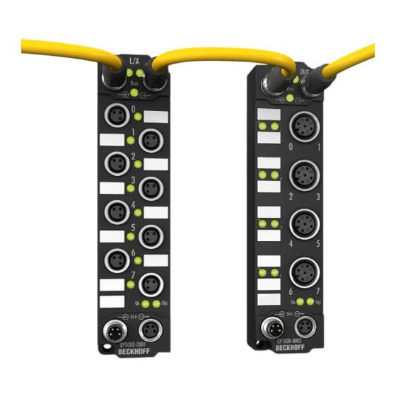
• digital outputs with 0.5 or 2 A output current • analog inputs and outputs with 16 bit resolution • Thermocouple and RTD inputs • Stepper motor modules XFC (eXtreme Fast Control Technology) modules, including inputs with time stamp, are also available. Version: 2.4 EP8309-1022... - Page 9 Fig. 3: EtherCAT Box with M12 connections for sensors/actuators Basic EtherCAT documentation You will find a detailed description of the EtherCAT system in the Basic System Documentation for EtherCAT, which is available for download from our website (www.beckhoff.com) under Downloads. EP8309-1022 Version: 2.4...
-
Page 10: Product Overview
24 V sensors. Proportional valves, for example, can be actuated directly using the PWM output, while intelligent valves are switched by the analog output. With its combination of inputs and outputs, the EP8309-1022 offers a compact solution for a wide variety of aggregates that are to be controlled via EtherCAT. -
Page 11: Technical Data
Product Overview Technical data Fieldbus Technical Data EP8309-1022 Fieldbus EtherCAT Fieldbus connection 2 x M8 socket (green) Tacho inputs Technical Data EP8309-1022 Number of tacho inputs 1 or 2 (dual-shaft mode or single-shaft mode) Input type Single-shaft mode: two digital sensors on a... - Page 12 Product Overview PWM outputs Technical Data EP8309-1022 Number of PWM outputs (alternatively analog output) Output connections [} 27] Load type ohmic/inductive > 1 mH Supply for the output stage 24 V via power contacts Output current per channel 1.2 A (short-circuit-proof, common thermal overload...
-
Page 13: Scope Of Supply
Scope of supply Make sure that the following components are included in the scope of delivery: • 1x EtherCAT Box EP8309-1022 • 2x protective cap for EtherCAT socket, M8, green (pre-assembled) • 1x protective cap for supply voltage input, M8, transparent (pre-assembled) •... -
Page 14: Process Image
Tacho dual-shaft mode (depending on the setting in the PDO assignment) The data for the tacho input can be found under TACHO Dual Shaft Mode Input Channel 1 or 2. see data under commissioning Version: 2.4 EP8309-1022... - Page 15 PWM output -> load-independent current, depending on module rating (e.g. 1.2 A and setting in object 0x8050:10) AO outputs (activated through PDO assignment 0x1603), not activated by default The values for the analog output can be found under AO Outputs. Analog Output - output value EP8309-1022 Version: 2.4...
-
Page 16: Pulse Width Modulation (Pwm)
Product Overview Pulse width modulation (PWM) The Beckhoff terminals and box modules integrate compact PWM output stages in the smallest of designs. PWM output stages control the output current through pulse width modulation (PWM) of the supply voltage. This means that the full supply voltage is activated or deactivated at the output. The duty cycle (pulse width) is modified, but not the voltage level. -
Page 17: Influencing Of The Pwm Output Value By The Parameters
Product Overview Influencing of the PWM output value by the parameters EP8309-1022 Version: 2.4... -
Page 18: Mounting And Cabling
Metal parts brass, nickel-plated Contacts CuZn, gold-plated Installation position variable Protection class IP65, IP66, IP67 (conforms to EN 60529) when screwed together Dimensions (H x W x D) approx. 126 x 60 x 26.5 mm (without connectors) Version: 2.4 EP8309-1022... -
Page 19: Fixing
• Protect the plug connectors against dirt during the assembly. Mount the module with two M4 screws in the centrally located mounting holes. 4.1.3 Tightening torques for plug connectors Screw connectors tight with a torque wrench. (e.g. ZB8801 from Beckhoff) Connector diameter Tightening torque 0.4 Nm 0.6 Nm... -
Page 20: Cabling
• digital In/Out channel 4 • digital In channel 2 / Tacho input Socket 4: Socket 8: • digital In/Out channel 3 • pulse width current output or • digital In/Out channel 4 • analog output Power In Power Out Version: 2.4 EP8309-1022... -
Page 21: Ethercat
For standardization, the core colors of the ZB9030, ZB9032 and ZK1090-3xxx-xxxx cables have been changed to the EN61918 core colors: yellow, orange, white, blue. So there are different color codes in circulation. The electrical properties of the cables have been retained when the core colors were changed. EP8309-1022 Version: 2.4... - Page 22 (CAT5) according to EN 50173 or ISO/IEC 11801 should be used. EtherCAT uses four wires for signal transmission. Thanks to automatic line detection ("Auto MDI-X"), both symmetrical (1:1) or cross-over cables can be used between Beckhoff EtherCAT. Detailed recommendations for the cabling of EtherCAT devices Version: 2.4...
-
Page 23: Supply Voltages
In some types of EtherCAT Box modules the ground potentials GND and GND are connected. • If several EtherCAT Box modules are supplied with the same electrically isolated voltages, check whether there is an EtherCAT Box among them in which the ground potentials are connected. EP8309-1022 Version: 2.4... - Page 24 Brown Peripheral voltage White GND to U Blue GND to U Black The core colors apply to cables of the type: Beckhoff ZK2020-3xxx-xxxx 4.2.3.2 Status LEDs Fig. 11: Status LEDs for the supply voltages Display Meaning (control voltage) The supply voltage U is not available.
- Page 25 Vert. Faktor: 0,45 cm / V Vert. Faktor: 0,4 0.34 mm² Vert. Faktor: 0,45 cm / V Vert. Faktor: 0.5 mm² 0.25 mm² 0.34 mm² 0.75 mm² 0.5 mm² 0.75 mm² Cable length (m) Cable length (m) EP8309-1022 Version: 2.4...
-
Page 26: Signal Connection
Pin 1 GNDp Pin 3 Input / Output A Pin 4 3-wire 2-wire 2-wire sensors sensors actuators or actuators The outputs are short-circuit proof and protected against polarity reversal. LEDs indicate the signal state of the outputs. Version: 2.4 EP8309-1022... - Page 27 PWM out / +24 V DC Up Pin 1 Analog out Pin 4 GND Analog Pin 2 GND PWM Pin 3 3-wire 2-wire analog The outputs are short-circuit proof. LEDs indicate the signal state of the output. EP8309-1022 Version: 2.4...
- Page 28 Correct function is indicated if the green Run LED is on and the red Error LED is off. Status LEDs at the M12 connections Connection Display Meaning M12 socket digital left / Input / output off or Low inputs/outputs right green Input / output on or High Version: 2.4 EP8309-1022...
-
Page 29: Ul Requirements
To meet the UL requirements, EtherCAT Box Modules has to be operated only at an ambient temperature range of -25 °C to +55 °C! Marking for UL All EtherCAT Box Modules certified by UL (Underwriters Laboratories) are marked with the following label. Fig. 13: UL label EP8309-1022 Version: 2.4... -
Page 30: Disposal
Products marked with a crossed-out wheeled bin shall not be discarded with the normal waste stream. The device is considered as waste electrical and electronic equipment. The national regulations for the disposal of waste electrical and electronic equipment must be observed. Version: 2.4 EP8309-1022... -
Page 31: Commissioning And Configuration
Commissioning and Configuration Commissioning and Configuration Integrating into a TwinCAT project The procedure for integration in a TwinCAT project is described in this Quick start guide. EP8309-1022 Version: 2.4... -
Page 32: Tacho Analysis
The velocity is lower than the limit in CoE 0x8020:12 Rotational Speed Threshold or = 0 threshold Rotational Speed Rotational speed and frequency, shown as a function of CoE object 0x80x0:15 Rotation Direction 0: rising edge of input A occurs before rising edge of input B Version: 2.4 EP8309-1022... - Page 33 Fig. 15: Tacho evaluation - display of the rotational speed Dual Shaft Mode The input PDOs 0x1A03 and 0x1A04 activate the two dual-shaft process data. The output data are always set. Fig. 16: Tacho evaluation - dual shaft mode EP8309-1022 Version: 2.4...
- Page 34 Reversion of rotation display in Rotation direction 80x0:11 No. of Targets Number of "cams" on the shaft/axis 80x0:12 Rotational Speed Threshold Limit value below which the corresponding status bit is set 80x0:15 Presentation Display of the measured value in RPM, Hz, … Version: 2.4 EP8309-1022...
-
Page 35: Switching Between Pwm And Analog Output
The 24V supply is switched on continuously. The different modes are activated via the PDO assignment. PWM mode The output PDO 0x1602 activates the PWM mode. Analog mode The output PDO 0x1603 activates the analog mode. EP8309-1022 Version: 2.4... - Page 36 Commissioning and Configuration Version: 2.4 EP8309-1022...
-
Page 37: Quick Start
The synchronous info data can be activated in the TwinCAT System Manager via the "Process Data" tab (0x1A07). Fig. 18: Info data objects - activation of the synchronous info data Objects 0x8050:21 [} 60] and 0x8050:22 [} 60] can be used to set the value to be transferred synchronously. EP8309-1022 Version: 2.4... - Page 38 The PWM duty cycle of the output stage. A value of 1000 corresponds to 100% duty cycle. Watchdog The analog output value can, e.g. in the case of a failure of communication with the controller, be set to a user-specific value. Version: 2.4 EP8309-1022...
- Page 39 To determine the settings a current pulse is applied to the load. This pulse can be picked up with an oscilloscope or with TwinCAT ScopeView. For evaluation with TwinCAT ScopeView the set and actual current is displayed in the synchronous info data. EP8309-1022 Version: 2.4...
- Page 40 This reduces static friction and prevents sudden "breakaway" of the piston. The configuration required for this depends a lot on the particular application. To activate dithering, the object 0x8050:03 [} 63] ("Enable dithering") and the corresponding control bit must be set. Version: 2.4 EP8309-1022...
- Page 41 The controller has 5 ms for compensating a current pulse of 10 %. The steepness of the current rise is limited by the controller parameters and the inductance. The actual current should follow the set current. This is enabled through suitable settings of the controller and dither parameters (frequency and amplitude). EP8309-1022 Version: 2.4...
- Page 42 Commissioning and Configuration EP8309 100 Hz dither with 10 % amplitude, poor parameterization (5 ms/div) Green: Set current EP8309 100 Hz dither with 10 % amplitude, Red: Actual current better parameterization (5 ms/div) Green: Set current Red: Actual current Version: 2.4 EP8309-1022...
-
Page 43: Range Settings For Inputs And Outputs
Object 0xF800:0 [} 64] contains the range settings for the inputs and outputs of channels 1 to 4. Fig. 23: CoE-Online tab Click on objects 0xF800:01 to 0xF800:04 to change the settings. Fig. 24: Changing the settings EP8309-1022 Version: 2.4... -
Page 44: Restore The Delivery State
ð All backup objects are reset to the delivery state. Alternative restore value With some older modules the backup objects can be changed with an alternative restore value: Decimal value: 1819238756 Hexadecimal value: 0x6C6F6164 An incorrect entry for the restore value has no effect. Version: 2.4 EP8309-1022... -
Page 45: Coe Parameters
Not every EtherCAT device must have a CoE list. Simple I/O modules without dedicated processor usually have no variable parameters and therefore no CoE list. If a device has a CoE list, it is shown in the TwinCAT System Manager as a separate tab with a listing of the elements: EP8309-1022 Version: 2.4... - Page 46 Changes in the local CoE list of the terminal are lost if the terminal is replaced. If a terminal is replaced with a new Beckhoff terminal, it will have the factory settings. It is therefore advisable to link all changes in the CoE list of an EtherCAT slave with the Startup list of the slave, which is processed whenever the EtherCAT fieldbus is started.
- Page 47 • the offline list from the ESI file is displayed. In this case modifications are not meaningful or possible. • the configured status is shown under Identity • no firmware or hardware version is displayed, since these are features of the physical device. • Offline is shown in red EP8309-1022 Version: 2.4...
- Page 48 • the actual current slave directory is read. This may take several seconds, depending on the size and cycle time. • the actual identity is displayed • the firmware and hardware version of the equipment according to the electronic information is displayed. • Online is shown in green Fig. 28: Online list Version: 2.4 EP8309-1022...
- Page 49 • Channel 1: parameter range x8010:00 ... x801F:255 • Channel 2: parameter range x8020:00 ... x802F:255 • … This is generally written as x80n0. Detailed information on the CoE interface can be found in the EtherCAT system documentation on the Beckhoff website. EP8309-1022 Version: 2.4...
-
Page 50: Object Overview
EtherCAT XML Device Description The display matches that of the CoE objects from the EtherCAT XML Device Description. We recommend downloading the latest XML file from the download area of the Beckhoff website and installing it according to installation instructions. - Page 51 0x6037:05, 1 1A02:06 SubIndex 006 0x0000:00, 3 1A02:07 SubIndex 007 0x0000:00, 3 1A02:08 SubIndex 008 0x6037:0C, 1 1A02:09 SubIndex 009 0x0000:00, 3 1A02:0A SubIndex 010 0x6037:10, 1 1A02:0B SubIndex 011 0x6037:11, 16 1A02:0C SubIndex 012 0x6037:12, 16 EP8309-1022 Version: 2.4...
- Page 52 SubIndex 001 0x6060:11, 16 [} 70]:0 1A07:02 SubIndex 002 0x6060:12, 16 Subindex Sync manager type 0x04 (4 1C00 [} 70]:0 1C00:01 SubIndex 001 0x01 (1 1C00:02 SubIndex 002 0x02 (2 1C00:03 SubIndex 003 0x03 (3 1C00:04 SubIndex 004 0x04 (4 Version: 2.4 EP8309-1022...
- Page 53 0x00000000 (0 1C33:08 Command 0x0000 (0 1C33:09 Maximum delay time 0x00000000 (0 1C33:0B SM event missed counter 0x0000 (0 1C33:0C Cycle exceeded counter 0x0000 (0 1C33:0D Shift too short counter 0x0000 (0 1C33:20 Sync error 0x00 (0 EP8309-1022 Version: 2.4...
- Page 54 0x00 (0 6040:02 Digital Input X4 Pin2 0x00 (0 6040:03 Digital Input X6 Pin4 0x00 (0 6040:04 Digital Input X6 Pin2 0x00 (0 6040:05 Digital Input X7 Pin4 0x00 (0 6040:06 Digital Input X7 Pin2 0x00 (0 Version: 2.4 EP8309-1022...
- Page 55 8000:14 Limit 2 0x0000 (0 8000:15 Filter settings 0x0000 (0 8000:17 User calibration offset 0x0000 (0 8000:18 User calibration gain 0x4000 (16384 Subindex AI Internal data Ch.1 0x01 (1 800E [} 76]:0 800E:01 ADC raw value 0x0000 (0 EP8309-1022 Version: 2.4...
- Page 56 TACHO Settings Single Shaft Mode 0x15 (21 8031 8031:0B Enable Error Detection 0x01 (1 [} 62]:0 8031:0C Reversion of Rotation 0x00 (0 8031:11 No. of Targets 0x0001 (1 8031:12 Input Signal Timeout 0x0064 (100 8031:15 Presentation 0x0000 (0 Version: 2.4 EP8309-1022...
- Page 57 PWM Diag data 0x06 (6 A060 A060:02 Overtemperature 0x00 (0 [} 77]:0 060A:06 Short circuit 0x00 (0 Subindex Modular device profile 0x02 (2 F000 [} 77]:0 F000:01 Module index distance 0x0010 (16 F000:02 Maximum number of modules 0x0008 (8 EP8309-1022 Version: 2.4...
- Page 58 0x00 (0 Subindex PWM Command 0x03 (3 FB00 FB00:01 Request [} 78]:0 FB00:02 Status 0x00 (0 FB00:03 Response Legend Flags: RO (Read Only): this object can only be read RW (Read/Write): this object can be read and written to Version: 2.4 EP8309-1022...
-
Page 59: Object Description And Parameterization
You can parameterize the box via the "CoE - Online" tab in TwinCAT. EtherCAT XML Device Description The presentation matches that of the EtherCAT XML Device Description. Recommendation: download the latest XML file from https://www.beckhoff.com/ and install it according to the installation instructions. Introduction The CoE overview contains objects for different intended applications: •... -
Page 60: Objects To Be Parameterized During Commissioning
60 Hz FIR IIR 1 IIR 2 IIR 3 IIR 4 IIR 5 IIR 6 IIR 7 IIR 8 8000:17 User calibration offset User calibration: Offset INT16 0x0000 (0 8000:18 User calibration gain User calibration: Gain INT16 0x4000 (16384 Version: 2.4 EP8309-1022... - Page 61 Input Signal Timeout The process record <Speed Below Threshold> is set UINT16 0x0064 after x msec without signal change at the input. (100 8030:15 Presentation Display of the measured value in RPM, Hz, … UINT16 0x0001 (1 EP8309-1022 Version: 2.4...
- Page 62 False 8040:05 X6 Pin2 Delay in msec after communication is canceled UINT16 False 8040:07 X7 Pin4 Delay in msec after communication is canceled UINT16 False 8040:08 X7 Pin2 Delay in msec after communication is canceled UINT16 False Version: 2.4 EP8309-1022...
- Page 63 0x0A (10 current (nominal box current * 0x8pp0:10) 8050:21 Select info data 1 Selection of synchronous info data (s. 0x6pp0:11) UINT8 0x00 (0 8050:22 Select info data 2 Selection of synchronous info data (s. 0x6pp0:12) UINT8 0x00 (0 EP8309-1022 Version: 2.4...
-
Page 64: Objects For Regular Operation
UINT16 0x0001 (1 F800:02 Input type Ch2 Select input type for Ch2 UINT16 0x0001 (1 F800:08 Output type Select input type for Ch1 UINT16 0x0001 (1 6.3.2 Objects for regular operation The EP8309 has no such objects. Version: 2.4 EP8309-1022... -
Page 65: Standard Objects (0X1000-0X1Fff)
Index (hex) Name Meaning Data type Flags Default 1008:0 Device name Device name of the EtherCAT slave STRING EP8309-1022 Index 1009 Hardware version Index (hex) Name Meaning Data type Flags Default 1009:0 Hardware version Hardware version of the EtherCAT slave... - Page 66 0x7060:07, 1 1602:05 SubIndex 005 5. PDO Mapping entry (object 0x7050 (DO Outputs), UINT32 0x0000:00, 9 entry 0x0E (Output 14)) 1602:06 SubIndex 006 6. PDO Mapping entry (object 0x7050 (DO Outputs), UINT32 0x7060:11, 16 entry 0x0E (Output 15)) Version: 2.4 EP8309-1022...
- Page 67 1A00:09 SubIndex 009 9. PDO Mapping entry (object 0x6000 (AI Inputs Ch.1), UINT32 0x6000:10, 1 entry 0x10 (TxPDO Toggle)) 1A00:0A SubIndex 010 10. PDO Mapping entry (object 0x6000 (AI Inputs Ch.1), UINT32 0x6000:11, 16 entry 0x11 (Value)) EP8309-1022 Version: 2.4...
- Page 68 11. PDO Mapping entry (object 0x6027 (TACHO Single UINT32 0x6037:11, 16 Shaft Mode Input), entry 0x11 (Rotational Speed)) 1A02:0C SubIndex 012 12. PDO Mapping entry (object 0x6027 (TACHO Single UINT32 0x6037:12, 16 Shaft Mode Input), entry 0x12 (Rotation Direction)) Version: 2.4 EP8309-1022...
- Page 69 0x6040:05, 1 Ch.1), entry 0x07 (Error)) 1A05:06 SubIndex 006 6. PDO Mapping entry (8 bits align) UINT32 0x6040:06, 1 1A05:07 SubIndex 007 7. PDO Mapping entry (object 0x6020 (PM Inputs Ch.1), UINT32 0x0000:00, 10 entry 0x10 (TxPDO Toggle)) EP8309-1022 Version: 2.4...
- Page 70 (5633 1C12:03 Subindex 003 3rd allocated RxPDO (contains the index of the UINT16 0x1602 associated RxPDO mapping object) (5634 1C12:04 Subindex 004 4th allocated RxPDO (contains the index of the UINT16 0x0000 (0 associated RxPDO mapping object) Version: 2.4 EP8309-1022...
- Page 71 (6662 1C13:06 Subindex 006 6th allocated TxPDO (contains the index of the UINT16 0x0000 (0 associated TxPDO mapping object) 1C13:07 Subindex 007 7th allocated TxPDO (contains the index of the UINT16 0x0000 (0 associated TxPDO mapping object) EP8309-1022 Version: 2.4...
- Page 72 Shift too short counter Number of occasions that the interval between SYNC0 UINT16 0x0000 (0 and SYNC1 event was too short (DC mode only) 1C32:20 Sync error The synchronization was not correct in the last cycle BOOLEAN 0x00 (0 (outputs were output too late; DC mode only) Version: 2.4 EP8309-1022...
- Page 73 UINT16 0x0000 (0 as 0x1C32:11 [} 72] counter 1C33:0C Cycle exceeded UINT16 0x0000 (0 as 0x1C32:12 [} 72] counter 1C33:0D Shift too short counter as 0x1C32:13 [} 72] UINT16 0x0000 (0 1C33:20 Sync error BOOLEAN 0x00 (0 as 0x1C32:32 [} 72] EP8309-1022 Version: 2.4...
-
Page 74: Profile-Specific Objects (0X6000-0Xffff)
Flags Default 6030:0 TACHO Dual Shaft UINT8 0x11 (17 Mode Input Ch.2 6030:01 Digital input BOOLEAN 0x00 (0 6030:0C Speed Below BOOLEAN 0x00 (0 Threshold 6030:10 TxPDO Toggle BOOLEAN 0x00 (0 6030:11 Rotational Speed INT16 0x0000 (0 Version: 2.4 EP8309-1022... - Page 75 Digital Output X5 Pin2 BOOLEAN 0x00 (0 7050:05 Digital Output X6 Pin4 BOOLEAN 0x00 (0 7050:06 Digital Output X6 Pin2 BOOLEAN 0x00 (0 7050:07 Digital Output X7 Pin4 BOOLEAN 0x00 (0 7050:08 Digital Output X7 Pin2 BOOLEAN 0x00 (0 EP8309-1022 Version: 2.4...
- Page 76 Index 805F PWM Vendor data Index (hex) Name Meaning Data type Flags Default 805F:0 PWM Vendor data UINT8 0x02 (2 805F:01 Offset Vendor calibration for +/-10 V INT16 0x0000 (0 805F:02 Gain Vendor calibration for +/-10 V INT16 0x4000 (16384 Version: 2.4 EP8309-1022...
- Page 77 (300 F010:03 SubIndex 003 UINT32 0x00000208 (520 F010:04 SubIndex 004 UINT32 0x00000208 (520 F010:05 SubIndex 005 UINT32 0x00000064 (100 F010:06 SubIndex 006 UINT32 0x000000C8 (200 F010:07 SubIndex 007 UINT32 0x000000FA (250 F010:08 SubIndex 008 UINT32 0x00000190 (400 EP8309-1022 Version: 2.4...
- Page 78 F900:02 Temperature [°C] UINT8 0x00 (0 Index FB00 PWM Command Index (hex) Name Meaning Data type Flags Default FB00:0 PWM Command UINT8 0x03 (3 FB00:01 Request OCTET- STRING[2] FB00:02 Status UINT8 0x00 (0 FB00:03 Response OCTET STRING[4] Version: 2.4 EP8309-1022...
-
Page 79: Diagnostics
Control voltage (Us) and peripheral voltage (Up) of the EP8309 Fig. 29: Diagnostic control voltage (Us) and peripheral voltage (Up) of the EP8309 DEV input process data Meaning Undervoltage Us Warning below 18 V Undervoltage Up Warning below 18 V EP8309-1022 Version: 2.4... -
Page 80: Appendix
(ph value > 12) unstable > 40 °C Acetic acid unstable Argon (technically pure) stable • resistant: Lifetime several months • non inherently resistant: Lifetime several weeks • not resistant: Lifetime several hours resp. early decomposition Version: 2.4 EP8309-1022... -
Page 81: Accessories
Torque cable key for M12 / wrench size 13 for ZB8801-0000 ZB8801-0003 Torque cable key for M12 field assembly / wrench size 18 for ZB8801-0000 Further accessories Further accessories can be found in the price list for fieldbus components from Beckhoff and online at https://www.beckhoff.com. EP8309-1022 Version: 2.4... -
Page 82: Version Identification Of Ethercat Devices
Associated and synonymous with each revision there is usually a description (ESI, EtherCAT Slave Information) in the form of an XML file, which is available for download from the Beckhoff web site. From 2014/01 the revision is shown on the outside of the IP20 terminals, see Fig. “EL2872 with revision 0022 and serial number 01200815”. -
Page 83: Version Identification Of Ip67 Modules
Version identification of IP67 modules The serial number/ data code for Beckhoff IO devices is usually the 8-digit number printed on the device or on a sticker. The serial number indicates the configuration in delivery state and therefore refers to a whole production batch, without distinguishing the individual modules of a batch. -
Page 84: Beckhoff Identification Code (Bic)
8.3.3 Beckhoff Identification Code (BIC) The Beckhoff Identification Code (BIC) is increasingly being applied to Beckhoff products to uniquely identify the product. The BIC is represented as a Data Matrix Code (DMC, code scheme ECC200), the content is based on the ANSI standard MH10.8.2-2016. - Page 85 Fig. 32: Example DMC 1P072222SBTNk4p562d71KEL1809 Q1 51S678294 An important component of the BIC is the Beckhoff Traceability Number (BTN, position 2). The BTN is a unique serial number consisting of eight characters that will replace all other serial number systems at Beckhoff in the long term (e.g.
-
Page 86: Electronic Access To The Bic (Ebic)
Electronic access to the BIC (eBIC) Electronic BIC (eBIC) The Beckhoff Identification Code (BIC) is applied to the outside of Beckhoff products in a visible place. If possible, it should also be electronically readable. The interface that the product can be electronically addressed by is crucial for the electronic readout. - Page 87 • The following auxiliary functions are available for processing the BIC/BTN data in the PLC in Tc2_Utilities as of TwinCAT 3.1 build 4024.24 ◦ F_SplitBIC: The function splits the Beckhoff Identification Code (BIC) sBICValue into its components using known identifiers and returns the recognized substrings in the ST_SplittedBIC structure as a return value ◦...
-
Page 88: Support And Service
Please contact your Beckhoff branch office or representative for local support and service on Beckhoff products! The addresses of Beckhoff's branch offices and representatives round the world can be found on her internet pages: www.beckhoff.com You will also find further documentation for Beckhoff components there. - Page 90 More Information: www.beckhoff.com/ep8309-1022 Beckhoff Automation GmbH & Co. KG Hülshorstweg 20 33415 Verl Germany Phone: +49 5246 9630 info@beckhoff.com www.beckhoff.com...
Need help?
Do you have a question about the EP8309-1022 and is the answer not in the manual?
Questions and answers