
Subscribe to Our Youtube Channel
Related Manuals for Beckhoff EP9224-2037


Summary of Contents for Beckhoff EP9224-2037
- Page 1 Documentation | EN EP9224-2037 EtherCAT Box, 4-port junction, with power supply, ENP, B17 2024-05-08 | Version: 1.0...
-
Page 3: Table Of Contents
Protective functions ......................... 35 5.2.1 Overload protection...................... 36 5.2.2 Overcurrent protection for sum currents ................ 38 5.2.3 Undervoltage protection .................... 39 5.2.4 Overtemperature protection ..................... 39 5.2.5 Warning and error messages................... 40 Diagnostic functions ........................ 41 5.3.1 Data logger........................ 41 EP9224-2037 Version: 1.0... - Page 4 Version identification of EtherCAT devices .................. 75 7.3.1 General notes on marking.................... 75 7.3.2 Version identification of IP67 modules ................ 76 7.3.3 Beckhoff Identification Code (BIC) ................... 77 7.3.4 Electronic access to the BIC (eBIC)................. 79 Support and Service........................ 81 Version: 1.0 EP9224-2037...
-
Page 5: Foreword
, XTS and XPlanar are registered trademarks of and licensed by Beckhoff Automation GmbH. Other designations used in this publication may be trademarks whose use by third parties for their own purposes could violate the rights of the owners. Patent Pending... -
Page 6: Safety Instructions
All the components are supplied in particular hardware and software configurations appropriate for the application. Modifications to hardware or software configurations other than those described in the documentation are not permitted, and nullify the liability of Beckhoff Automation GmbH & Co. KG. Personnel qualification This description is only intended for trained specialists in control, automation and drive engineering who are familiar with the applicable national standards. -
Page 7: Documentation Issue Status
YY - year of production 10 - year of production 2010 FF - firmware version 02 - firmware version 02 HH - hardware version 01 - hardware version 01 Further information on this topic: Version identification of EtherCAT devices [} 75]. EP9224-2037 Version: 1.0... -
Page 8: Ethercat Box - Introduction
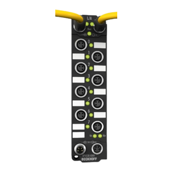
• digital outputs with 0.5 or 2 A output current • analog inputs and outputs with 16 bit resolution • Thermocouple and RTD inputs • Stepper motor modules XFC (eXtreme Fast Control Technology) modules, including inputs with time stamp, are also available. Version: 1.0 EP9224-2037... - Page 9 Fig. 3: EtherCAT Box with M12 connections for sensors/actuators Basic EtherCAT documentation You will find a detailed description of the EtherCAT system in the Basic System Documentation for EtherCAT, which is available for download from our website (www.beckhoff.com) under Downloads. EP9224-2037 Version: 1.0...
-
Page 10: Product Overview
+24 V U +24 V U The EP9224-2037 allows the distribution of one B17 ENP input to four EtherCAT ports and M8 power supply ports with B17-ENP forwarding. In each voltage branch, the current consumption for control voltage U peripheral voltage U is monitored, limited and, if necessary, switched off. -
Page 11: Technical Data
Adjustable, see chapter Switch output voltages [} 47]. • "Fast" = 10 ms • "Moderate" = 100 ms (default) • "Slow" = 200 ms Total power loss max. 12 W at full load. (4 A output current per U and U at all outputs at 24 V supply voltage) EP9224-2037 Version: 1.0... - Page 12 Protection class IP65, IP66, IP67 (conforms to EN 60529) Approvals / markings Approvals / markings CE, UL under preparation *) Real applicable approvals/markings see type plate on the side (product marking). Additional tests The devices have undergone the following additional tests: Version: 1.0 EP9224-2037...
- Page 13 Product overview Test Explanation Vibration 10 frequency sweeps in 3 axes 5 Hz < f < 60 Hz displacement 0.35 mm, constant amplitude 60.1 Hz < f < 500 Hz acceleration 5 g, constant amplitude Shocks 1000 shocks in each direction, in 3 axes 35 g, 11 ms EP9224-2037 Version: 1.0...
-
Page 14: Scope Of Supply
Product overview Scope of supply Make sure that the following components are included in the scope of delivery: • 1x EP9224-2037 • 4x protective cap for M8 socket, black (pre-assembled) • 4x protective cap for EtherCAT socket, M8, green (pre-assembled) •... -
Page 15: Process Image
Output bits of the channels. DPO Outputs Device Output bits of the entire device. WcState and InfoData EtherCAT system variables. EP9224-3037 I/O module that represents the second EtherCAT Slave Controller in the device. See chapter Basic Function Principles [} 19]. EP9224-2037 Version: 1.0... - Page 16 Warning Sum Current: The sum current I + I of the channel currently exceeds the nominal sum current (CoE parameter 80n0:14). If the overcurrent persists, the channel is switched off. Current Us, Current Up: 16-bit measured values of the current output currents. Version: 1.0 EP9224-2037...
- Page 17 DPO Outputs Channel 1 to 4 Output data for the individual channels. Output U , Output U : Switches the respective output voltage on or off. Reset U , Reset U : Reset the error state of the respective output voltage. EP9224-2037 Version: 1.0...
- Page 18 "Output Us" and "Output Up". • FALSE: Enables the automatic switching on of the output voltages according to the CoE parameters 80n0:02 and 80n0:03. Global Reset: Reset the error state of the device and all channels. Version: 1.0 EP9224-2037...
-
Page 19: Basic Function Principles
The following figure shows the logical path of an EtherCAT frame through the two ESCs. The ports on an ESC that do not have a device connected are automatically bypassed. Port D Port C Port D Port C EP9224-2037 Version: 1.0... -
Page 20: Mounting And Cabling
15.5 A at 45 °C (B17 5G 1.5 mm Installation position variable Protection class IP65, IP66, IP67 (conforms to EN 60529) when screwed together Dimensions (H x W x D) approx. 150 x 60 x 26.5 mm (without connectors) Version: 1.0 EP9224-2037... -
Page 21: Fixing
4.1.3 Tightening torques for plug connectors M8 connector Screw M8 connectors tight with a torque wrench. (e.g. ZB8801 from Beckhoff) Torque: 0.4 Nm. B17 connector Screw B17 connectors tight by hand: Plug the cable connector into the connector on the box to the stop. Turn the cap nuts of the cable connector clockwise by about 1/8 of a turn to the stop. -
Page 22: Functional Earth (Fe)
• If the remote station is a device with B17 connector: connect the devices with a pre-configured cable. See chapter Accessories [} 74]. • Otherwise: ground the "PE" core with low impedance as near as possible to the remote station. • Leave the cap nuts and housing of the B17 connectors without contact. Version: 1.0 EP9224-2037... -
Page 23: Supply Voltage Input And Downstream Connection
In some types of EtherCAT Box modules the ground potentials GND and GND are connected. • If several EtherCAT Box modules are supplied with the same electrically isolated voltages, check whether there is an EtherCAT Box among them in which the ground potentials are connected. EP9224-2037 Version: 1.0... -
Page 24: Connection
FE: functional earth green-yellow : peripheral voltage, +24 V black : ground for U blue : control voltage +24 V brown The core colors apply to cables, connectors and flanges of the type • Beckhoff ZB7203-xxxx • Beckhoff ZK7208-xxxx Version: 1.0 EP9224-2037... -
Page 25: Status Leds
Voltage drop on the supply line 1.5 mm² 2.5 mm² 16 A Vert. Faktor: 0,45 cm / V Vert. Faktor: 0,4 12 A 16 A Vert. Faktor: 0,45 cm / V Vert. Faktor: 12 A Cable length (m) Cable length (m) EP9224-2037 Version: 1.0... -
Page 26: Supply Voltage Outputs
The supply voltage outputs X60 ... X63 are implemented as M8 sockets. Contact Function Description Core color Control voltage Brown Peripheral voltage White GND to U Blue GND to U Black The core colors apply to M8 cables from Beckhoff. See chapter Accessories [} 74]. Version: 1.0 EP9224-2037... -
Page 27: Status Leds
Lights up red Error message [} 40]. At least one of the output voltages has been switched off due to a protective function. Chaser light red Error message [} 40]. (all four status LEDs) Undervoltage or overtemperature. EP9224-2037 Version: 1.0... -
Page 28: Ethercat Input And Downstream Connection
• 5-pin power supply unit Shield Shield Fig. 5: EtherCAT pin assignment Voltage/signal Core colors yellow white blue orange Shroud Shield Cable shield The core colors apply to cables, connectors and flanges of the type • Beckhoff ZB7203-xxxx • Beckhoff ZK7208-xxxx Version: 1.0 EP9224-2037... -
Page 29: Status Leds
Each EtherCAT slave and each EtherCAT P slave has a green LED labeled "Run". The LED signals the status of the slave in the EtherCAT network: Meaning Slave is in "Init" state flashes uniformly Slave is in "Pre-Operational“ state flashes sporadically Slave is in "Safe-Operational" state Slave is in "Operational" state EP9224-2037 Version: 1.0... -
Page 30: Ethercat Ports X40
For standardization, the core colors of the ZB9030, ZB9032 and ZK1090-3xxx-xxxx cables have been changed to the EN61918 core colors: yellow, orange, white, blue. So there are different color codes in circulation. The electrical properties of the cables have been retained when the core colors were changed. Version: 1.0 EP9224-2037... -
Page 31: Status Leds
(CAT5) according to EN 50173 or ISO/IEC 11801 should be used. EtherCAT uses four wires for signal transmission. Thanks to automatic line detection ("Auto MDI-X"), both symmetrical (1:1) or cross-over cables can be used between Beckhoff EtherCAT. Detailed recommendations for the cabling of EtherCAT devices EP9224-2037... -
Page 32: Disposal
Products marked with a crossed-out wheeled bin shall not be discarded with the normal waste stream. The device is considered as waste electrical and electronic equipment. The national regulations for the disposal of waste electrical and electronic equipment must be observed. Version: 1.0 EP9224-2037... -
Page 33: Commissioning And Configuration
The procedure for integration in a TwinCAT project is described in these Quick start guide. 5.1.1 Assignment of the connections This chapter describes the assignment of the EtherCAT connections of an EP9224-2037 to their representation in TwinCAT. This assignment is required to correctly map an EtherCAT network in TwinCAT "offline" configuration. - Page 34 Example: Appending an EtherCAT Box to EP9224-2037 ü Requirement: an EP9224-2037 is appended in the I/O tree in TwinCAT. 1. Decide to which connector of the EP9224-2037 the EtherCAT Box is to be connected. (e.g. to X42) 2. Determine the corresponding I/O module and port with the help of the table.
-
Page 35: Protective Functions
"DPO Outputs Device" > "Global Reset". Note: The designation "Reset" refers only to the error state. Parameters and settings remain unchanged. Further information can be found in the sections "Resetting an error state" in the chapter for the individual protective functions. EP9224-2037 Version: 1.0... -
Page 36: Overload Protection
• The output voltage status LED of the output lights up red. Resetting an error state If an output voltage has been switched off by the overload protection, it can be enabled again by one of the following actions: Version: 1.0 EP9224-2037... - Page 37 % of the nominal Very fast acting Fast acting Slow acting Time delay current 105 % 3600 s 3600 s 3600 s 3600 s 135 % 420 s 3600 s 3600 s 3600 s 200 % 0.5 s 20 s 20 s 100 s 300 % 0.02 s 0.1 s 1 s 3 s EP9224-2037 Version: 1.0...
-
Page 38: Overcurrent Protection For Sum Currents
Commissioning and configuration 5.2.2 Overcurrent protection for sum currents EP9224-2037 determines two types of sum currents: • Sum current for each individual output (calculated) + U • Sum current for all outputs (measured) ∑ (U + U The overcurrent protection for sum currents is disabled in the factory settings. It can be individually activated... -
Page 39: Undervoltage Protection
2. Apply a positive edge to the output variable „DPO Outputs Device“ > „Global Reset“. ð The error message is reset. ð All output voltages are switched on again if no other protective function signals an error. EP9224-2037 Version: 1.0... -
Page 40: Warning And Error Messages
(n = 0 for X60, n = 1 for X61, n = 2 for X62, n = 3 for X63) Status bit Responsible protective function Error Us Overload protection [} 36] Error Up Warning Us Warning Up Error Sum Current Overcurrent protection for sum currents [} 38] Warning Sum Current Version: 1.0 EP9224-2037... -
Page 41: Diagnostic Functions
• PDO 0x1610 (Sync Manager SM2 "Outputs") • PDO 0x1A10 (Sync Manager SM3 "Inputs") Proceed as follows: ü Requirement: an EP9224-2037 is appended in the I/O tree in TwinCAT. 1. Double-click on the EP9224-2037 I/O module in the I/O tree. 2. Click the Process Data tab. - Page 42 Proceed as follows to upload the recorded measured values to the control computer: 1. Double-click on the EP9224-2037 I/O module in the I/O tree. 2. Click the "Online" tab. 3. Click the Upload button.
- Page 43 The data upload was started before the recording was stopped. Hardware Protection The starting current limitation has switched off an output voltage. User Stop Bit Set the bit "Stop Logger" in the process data. Logger still running N/A. The recording has not yet been stopped. EP9224-2037 Version: 1.0...
-
Page 44: Peak Value Detector
The value of the maximum extreme value and the time of occurrence in input variables are available at all times. The following diagrams illustrate the mode of operation of the peak value detector taking the example of the maximum of a measured variable: Measured variable Peak value Timestamp Version: 1.0 EP9224-2037... - Page 45 Outputs Device Inputs Device Proceed as follows: 1. Double-click on the EP9224-2037 I/O module in the I/O tree. 2. Click the Process Data tab. 3. Click "Outputs" in the "Sync Manager" box. 4. Activate the PDO Assignment (0x1C12) checkbox next to the desired PDOs.
- Page 46 To do this, apply a positive edge to the respective output variable "Reset Extended Diag Data". Evaluation The peak values and timestamp can be found in the process data objects "DPO Extended Diag Inputs" as input variables: • "Peak Value 1" and the associate "Timestamp 1" • "Peak Value 2" and the associate "Timestamp 2" Version: 1.0 EP9224-2037...
-
Page 47: Switch Output Voltages
You can set the time offset in CoE index F80E:11 "Startup Delay": • "0": "Fast" • "1": "Moderate" • "2": "Slow" Manual switching Set the variable "Enable Control Via Fieldbus" to "1" to switch output voltages manually via output variables. EP9224-2037 Version: 1.0... - Page 48 "DPO Outputs Channel 1" > "Output Us" "DPO Outputs Channel 1" > "Output Up" "DPO Outputs Channel 2" > "Output Us" "DPO Outputs Channel 2" > "Output Up" "DPO Outputs Channel 3" > "Output Us" "DPO Outputs Channel 3" > "Output Up" "DPO Outputs Channel 4" > "Output Us" "DPO Outputs Channel 4" > "Output Up" Version: 1.0 EP9224-2037...
-
Page 49: Restore The Delivery State
ð All backup objects are reset to the delivery state. Alternative restore value With some older modules the backup objects can be changed with an alternative restore value: Decimal value: 1819238756 Hexadecimal value: 0x6C6F6164 An incorrect entry for the restore value has no effect. EP9224-2037 Version: 1.0... -
Page 50: Coe Parameters
You can parameterize the box via the "CoE - Online" tab in TwinCAT. EtherCAT XML Device Description The presentation matches that of the EtherCAT XML Device Description. Recommendation: download the latest XML file from https://www.beckhoff.com/ and install it according to the installation instructions. Objects for parameterization... - Page 51 • 8: Warning Sum Current • 16: Minimum Current Us • 17: Maximum Current Us • 18: Minimum Current Up • 19: Maximum Current Up See chapter Peak value detector [} 44]. 8000:16 Timestamp 2 Trigger See 8000:15. UINT16 0x0000 (0 EP9224-2037 Version: 1.0...
- Page 52 • 8: Warning Sum Current • 16: Minimum Current Us • 17: Maximum Current Us • 18: Minimum Current Up • 19: Maximum Current Up See chapter Peak value detector [} 44]. 8010:16 Timestamp 2 Trigger See 8010:15. UINT16 0x0000 (0 Version: 1.0 EP9224-2037...
- Page 53 • 8: Warning Sum Current • 16: Minimum Current Us • 17: Maximum Current Us • 18: Minimum Current Up • 19: Maximum Current Up See chapter Peak value detector [} 44]. 8020:16 Timestamp 2 Trigger See 8020:15 UINT16 0x0000 (0 EP9224-2037 Version: 1.0...
- Page 54 • 8: Warning Sum Current • 16: Minimum Current Us • 17: Maximum Current Us • 18: Minimum Current Up • 19: Maximum Current Up See chapter Peak value detector [} 44]. 8030:16 Timestamp 2 Trigger See 8030:15 UINT16 0x0000 (0 Version: 1.0 EP9224-2037...
- Page 55 See chapter Switch output voltages [} 47]. 707F:04 Global Reset Reset all errors. BOOLEAN 0x00 (0 707F:11 Reset Extended Diag Data Reset all values of the peak value detector. BOOLEAN 0x00 (0 See chapter Peak value detector [} 44]. EP9224-2037 Version: 1.0...
- Page 56 • 21: Maximum Voltage Us • 22: Minimum Voltage Up • 23: Maximum Voltage Up • 24: Minimum Temperature • 25: Maximum Temperature See chapter Peak value detector [} 44]. F80E:16 Timestamp 2 Trigger See F80E:15. UINT16 0x0000 (0 Version: 1.0 EP9224-2037...
-
Page 57: Standard Objects
Index Name Meaning Data type Flags Default (hex) 1008:0 Device name Device name of the EtherCAT slave STRING EP9224-2037 Index 1009 Hardware version Index Name Meaning Data type Flags Default (hex) 1009:0 Hardware version Hardware version of the EtherCAT slave... - Page 58 Diag Outputs Ch.2 1603:01 SubIndex 001 1. PDO Mapping entry (object 0x7010 (DPO Outputs UINT32 0x7010:11, 1 Ch.2), entry 0x11 (Reset Extended Diag Data)) 1603:02 SubIndex 002 2. PDO Mapping entry (15 bits align) UINT32 0x0000:00, 15 Version: 1.0 EP9224-2037...
- Page 59 2. PDO Mapping entry (2 bits align) UINT32 0x0000:00, 2 1608:03 SubIndex 003 3. PDO Mapping entry (object 0xF707 (DPO Outputs UINT32 0xF707:04, 1 Device), entry 0x04 (Global Reset)) 1608:04 SubIndex 004 4. PDO Mapping entry (12 bits align) UINT32 0x0000:00, 12 EP9224-2037 Version: 1.0...
- Page 60 SubIndex 013 13. PDO Mapping entry (object 0x6000 (DPO Inputs UINT32 0x6000:11, 16 Ch.1), entry 0x11 (Current Us)) 1A00:0E SubIndex 014 14. PDO Mapping entry (object 0x6000 (DPO Inputs UINT32 0x6000:12, 16 Ch.1), entry 0x12 (Current Up)) Version: 1.0 EP9224-2037...
- Page 61 SubIndex 003 3. PDO Mapping entry (object 0x6010 (DPO Inputs UINT32 0x6010:17, 64 Ch.2), entry 0x17 (Timestamp 1)) 1A03:04 SubIndex 004 4. PDO Mapping entry (object 0x6010 (DPO Inputs UINT32 0x6010:18, 64 Ch.2), entry 0x18 (Timestamp 2)) EP9224-2037 Version: 1.0...
- Page 62 SubIndex 003 3. PDO Mapping entry (object 0x6020 (DPO Inputs UINT32 0x6020:17, 64 Ch.3), entry 0x17 (Timestamp 1)) 1A05:04 SubIndex 004 4. PDO Mapping entry (object 0x6020 (DPO Inputs UINT32 0x6020:18, 64 Ch.3), entry 0x18 (Timestamp 2)) Version: 1.0 EP9224-2037...
- Page 63 SubIndex 003 3. PDO Mapping entry (object 0x6030 (DPO Inputs UINT32 0x6030:17, 64 Ch.4), entry 0x17 (Timestamp 1)) 1A07:04 SubIndex 004 4. PDO Mapping entry (object 0x6030 (DPO Inputs UINT32 0x6030:18, 64 Ch.4), entry 0x18 (Timestamp 2)) EP9224-2037 Version: 1.0...
- Page 64 0x0000:00, 15 1A10:03 SubIndex 003 3. PDO Mapping entry (object 0x6040 (LOG Status), UINT32 0x6040:11, 32 entry 0x11 (Elapsed Time)) 1A10:04 SubIndex 004 4. PDO Mapping entry (object 0x6040 (LOG Status), UINT32 0x6040:12, 16 entry 0x12 (Trigger Reason)) Version: 1.0 EP9224-2037...
- Page 65 TxPDO mapping object) 1C13:0A Subindex 010 10. allocated TxPDO (contains the index of the UINT16 0x0000 (0 associated TxPDO mapping object) 1C13:0B Subindex 011 11. allocated TxPDO (contains the index of the UINT16 0x0000 (0 associated TxPDO mapping object) EP9224-2037 Version: 1.0...
- Page 66 Number of occasions that the interval between UINT16 0x0000 (0 SYNC0 and SYNC1 event was too short (DC mode only) 1C32:20 Sync error The synchronization was not correct in the last cycle BOOLEAN 0x00 (0 (outputs were output too late; DC mode only) Version: 1.0 EP9224-2037...
- Page 67 1C33:0B SM event missed counter as 1C32:11 UINT16 0x0000 (0 1C33:0C Cycle exceeded counter as 1C32:12 UINT16 0x0000 (0 1C33:0D Shift too short counter as 1C32:13 UINT16 0x0000 (0 1C33:20 Sync error as 1C32:32 BOOLEAN 0x00 (0 EP9224-2037 Version: 1.0...
-
Page 68: Profile-Specific Objects
BOOLEAN 0x00 (0 6010:11 Current Us INT16 0x0000 (0 6010:12 Current Up INT16 0x0000 (0 6010:13 Peak Value 1 INT16 0x0000 (0 6010:14 Peak Value 2 INT16 0x0000 (0 6010:17 Timestamp 1 UINT64 6010:18 Timestamp 2 UINT64 Version: 1.0 EP9224-2037... - Page 69 Timestamp 2 UINT64 Index 6040 LOG Status Index Name Meaning Data type Flags Default (hex) 6040:0 LOG Status UINT8 0x12 (18 6040:01 Logger Running BOOLEAN 0x00 (0 6040:11 Elapsed Time UINT32 0x00000000 6040:12 Trigger Reason UINT16 0x0000 (0 EP9224-2037 Version: 1.0...
- Page 70 Index 800F DPO Vendor data Ch.1 Index Name Meaning Data type Flags Default (hex) 800F:0 DPO Vendor data Ch.1 UINT8 0x14 (20 800F:11 GainS UINT16 0x4000 (16384 800F:12 OffsetS INT16 0x0000 (0 800F:13 GainP UINT16 0x4000 (16384 800F:14 OffsetP INT16 0x0000 (0 Version: 1.0 EP9224-2037...
- Page 71 Index distance of the objects of the individual UINT16 0x0010 (16 channels F000:02 Maximum number of modules Number of channels UINT16 0x0005 (5 Index F008 Code word Index Name Meaning Data type Flags Default (hex) F008:0 Code word UINT32 0x00000000 EP9224-2037 Version: 1.0...
- Page 72 0x0000 (0 F81F:15 Gain US UINT16 0x4000 (16384 F81F:16 Offset US INT16 0x0000 (0 F81F:17 Gain UP UINT16 0x4000 (16384 F81F:18 Offset UP INT16 0x0000 (0 F81F:19 Gain Temperature UINT16 0x4000 (16384 F81F:1A Offset Temperature INT16 0x0000 (0 Version: 1.0 EP9224-2037...
-
Page 73: Appendix
(ph value > 12) unstable > 40 °C Acetic acid unstable Argon (technically pure) stable • resistant: Lifetime several months • non inherently resistant: Lifetime several weeks • not resistant: Lifetime several hours resp. early decomposition EP9224-2037 Version: 1.0... -
Page 74: Accessories
ZB8801-0000 Torque wrench for plugs, 0.4…1.0 Nm ZB8801-0001 Torque cable key for M8 / wrench size 9 for ZB8801-0000 Further accessories Further accessories can be found in the price list for fieldbus components from Beckhoff and online at https://www.beckhoff.com. Version: 1.0 EP9224-2037... -
Page 75: Version Identification Of Ethercat Devices
Associated and synonymous with each revision there is usually a description (ESI, EtherCAT Slave Information) in the form of an XML file, which is available for download from the Beckhoff web site. From 2014/01 the revision is shown on the outside of the IP20 terminals, see Fig. “EL2872 with revision 0022 and serial number 01200815”. -
Page 76: Version Identification Of Ip67 Modules
Version identification of IP67 modules The serial number/ data code for Beckhoff IO devices is usually the 8-digit number printed on the device or on a sticker. The serial number indicates the configuration in delivery state and therefore refers to a whole production batch, without distinguishing the individual modules of a batch. -
Page 77: Beckhoff Identification Code (Bic)
7.3.3 Beckhoff Identification Code (BIC) The Beckhoff Identification Code (BIC) is increasingly being applied to Beckhoff products to uniquely identify the product. The BIC is represented as a Data Matrix Code (DMC, code scheme ECC200), the content is based on the ANSI standard MH10.8.2-2016. - Page 78 Fig. 9: Example DMC 1P072222SBTNk4p562d71KEL1809 Q1 51S678294 An important component of the BIC is the Beckhoff Traceability Number (BTN, position 2). The BTN is a unique serial number consisting of eight characters that will replace all other serial number systems at Beckhoff in the long term (e.g.
-
Page 79: Electronic Access To The Bic (Ebic)
Electronic access to the BIC (eBIC) Electronic BIC (eBIC) The Beckhoff Identification Code (BIC) is applied to the outside of Beckhoff products in a visible place. If possible, it should also be electronically readable. The interface that the product can be electronically addressed by is crucial for the electronic readout. - Page 80 • The following auxiliary functions are available for processing the BIC/BTN data in the PLC in Tc2_Utilities as of TwinCAT 3.1 build 4024.24 ◦ F_SplitBIC: The function splits the Beckhoff Identification Code (BIC) sBICValue into its components using known identifiers and returns the recognized substrings in the ST_SplittedBIC structure as a return value ◦...
-
Page 81: Support And Service
Please contact your Beckhoff branch office or representative for local support and service on Beckhoff products! The addresses of Beckhoff's branch offices and representatives round the world can be found on her internet pages: www.beckhoff.com You will also find further documentation for Beckhoff components there. - Page 83 More Information: www.beckhoff.com/ep9224-2037 Beckhoff Automation GmbH & Co. KG Hülshorstweg 20 33415 Verl Germany Phone: +49 5246 9630 info@beckhoff.com www.beckhoff.com...
Need help?
Do you have a question about the EP9224-2037 and is the answer not in the manual?
Questions and answers